Project 3
Design and simulation of Buck converter for Auxiliary load in EV.
- Input voltage is 48V, Output voltage is 12 V
- Load current is 10A
- Calculate Duty ratio and Load(use Resistor as Load)
- Calculate L,C
A)given,
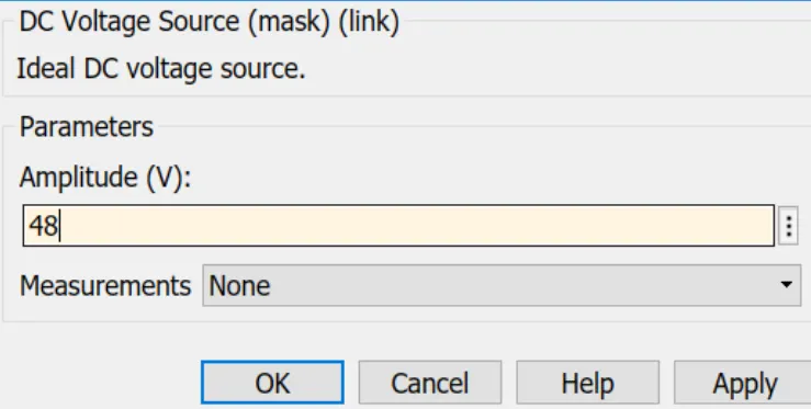
Vin = 48V
Vout = 12V
load Current = 10A
Calculate Duty ratio and Load(use Resistor as Load) = ?
Calculate L,C =?
Based on the above parameters we have to Design and done the simulation of Buck converter for Auxiliary load in EV.
There are some Steps should follow for Designing of Buck converter
Step 1: Draw a circuit Schematic diagram of the buck converter
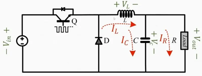
Step 2: Draw the Converter Circuit in ON & OFF mode.
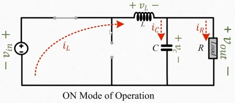
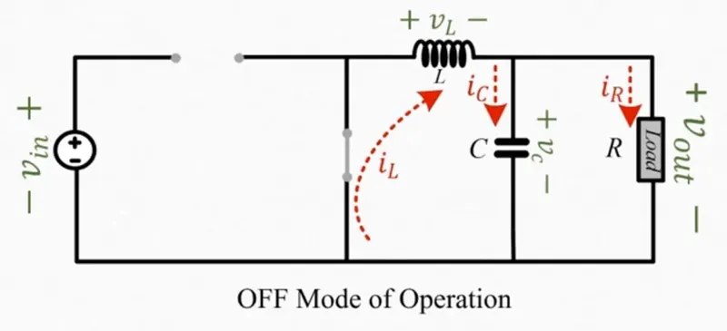
Step3: Calculation
Vl = Von DT + Voff(1-d)T/T = 0
Von = vin - vout
Voff = -Vout
D = Vout/Vin = 12/48 = 0.25
here duty cycle is 0.25
Vout = IoutR
R = Vout/Iout = 12/10 = 1.2ohm
let us design for 30%ripple in the inductor
IL = 30/100 * 5 = 1.5A
to calculate the inductor value we use below formula
L = (Vout/Fs*Il)(1-D)
L = 12 *0.75/10*1.5 = 0.12mh =L
Cout = 1-D / 8Lf^2(delta Vout/Vout) = 0.00625f
So, we got the values of,
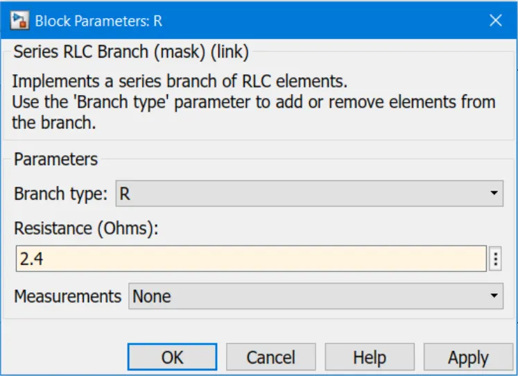
R = 1.2ohm
L = 0.12mH
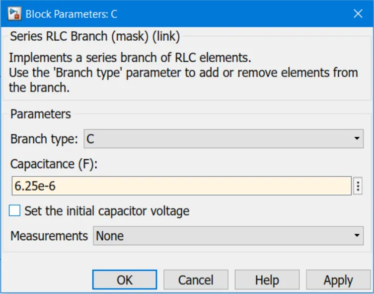
C = 6.25uf
D = 25%
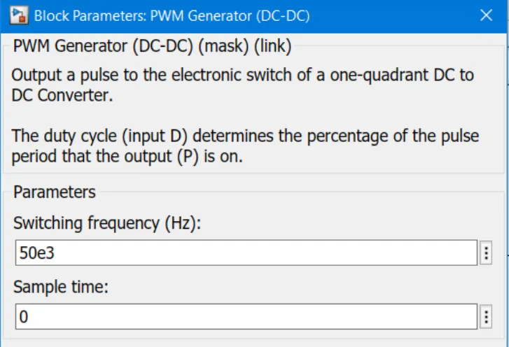
Assumption f= 50kHz
Step4: Now we have to design the circuit in MATLAB Simulink software to know the peak voltage and current values of my switches
Simulink Model
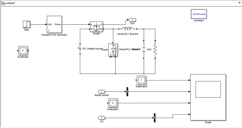
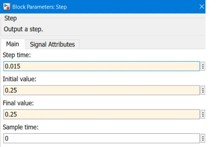
MOSFET Current and Diode Current
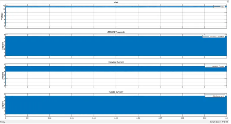
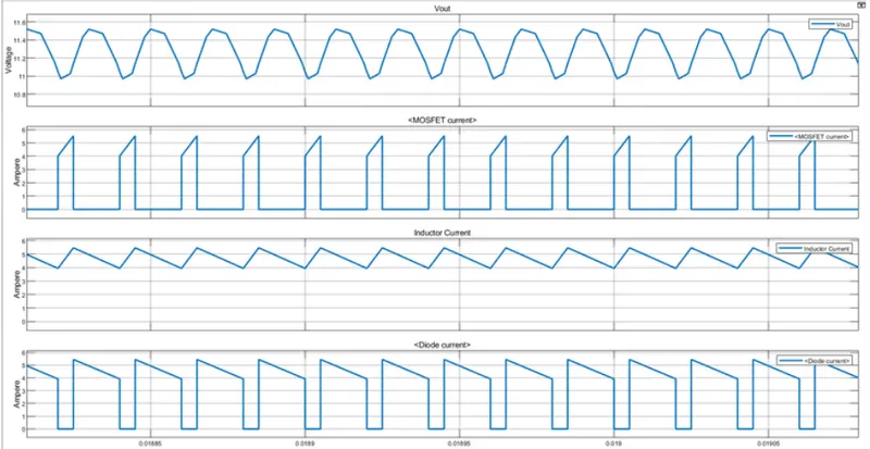
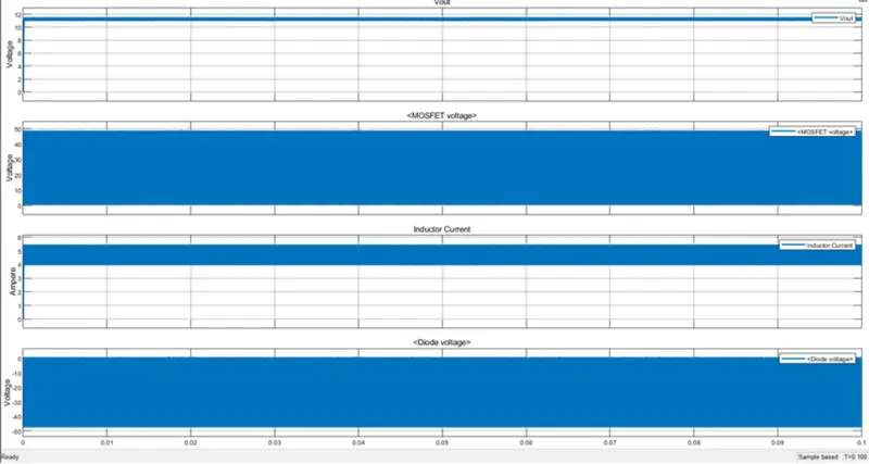
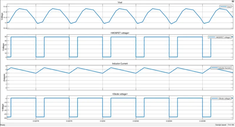
Peak Current of Mosfet = 10A
Peak Current of Diode = 10.4A
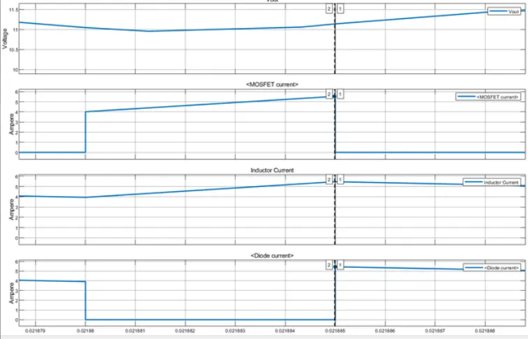
Conclusion: so Based on the calculations of parameters like L,C and R and also duty cycle we have designed the BUCK CONVERTER in Simulink model