Project 2 Thermal modeling of battery pack
Aim:
We need to simulate a thermal effects and Compare the life cycle performance at various temperature, charge and discharge rate of a 10 cell series lithium ion battery model
here we go, In this model we gonna use Lithium ion batteries
Introduction
The Lithium-ion batteries are widely used as energy sources in different hybrid and electric vehicle, however, the operation characteristics of the battery in such vehicle are strongly dependent on the operation temperature and therefore, with purpose to improve these characteristics a good thermal control system should be utilized.
The temperature of a Lithium battery cell is important for its performance, efficiency, safety, and capacity and is influenced by the environmental temperature and by the charging and discharging process itself. Therefore, a thermal model of the battery is used in order to calculate and estimate the cell temperature.
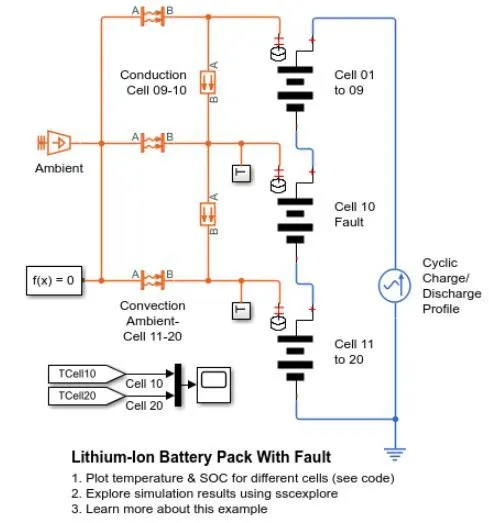
Lithium-Ion Battery Pack with Fault is to simulate a battery pack consisting of multiple series connected cells in an efficient manner. It also shows how a fault can be introduced into one of the cells to see the impact on battery performance and cell temperatures.
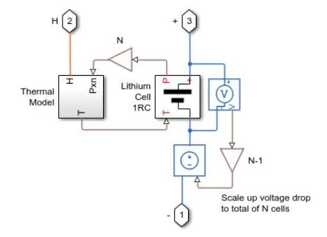
For efficiency, identical series-connected cells are not just simply modelled by connecting cell models in series. Instead a single cell is used, and the terminal voltage scaled up by the number of cells. The fault is represented by changing the parameters for the Cell 5 Fault subsystem, reducing both capacity and open-circuit voltage, and increasing the resistance values.
Here is the default MATLAB Simulink Model of Battery Pack which been extracted from Matlab help desk with the command code of SSC_LITHIUM_BATTERY _WITH_FAULT .
In which i have used for 10-cell battery pack thermal modelling.
Description :
In the above Modified model we have:
1. Lithum cell(one RC-branch equivalent circuit):

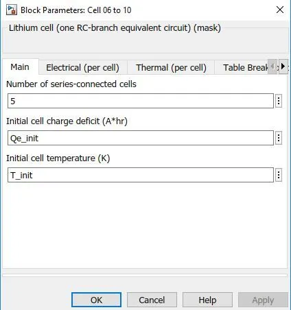
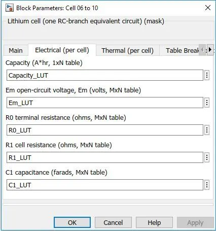
In the model we gonna use 3 Lithium cell (One RC branch equivalent circuit) amoung those ,
- First one with 4 no of series connected cells
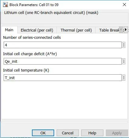
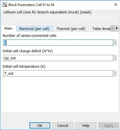
- Second one with 1 no of series connected cells
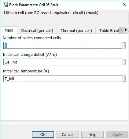
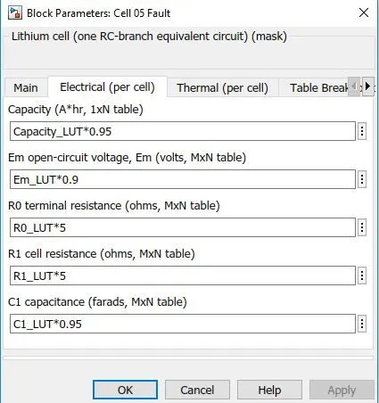
- Third one with 5 no of series connected cells
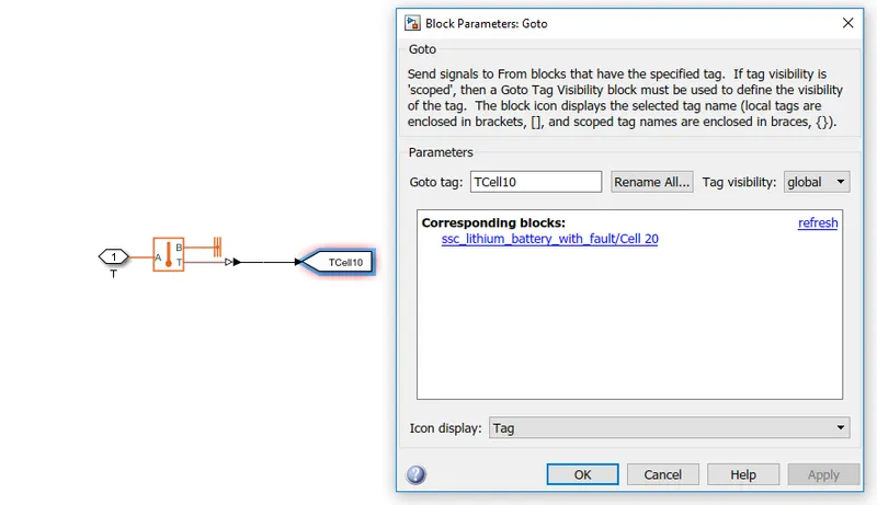
2. Goto : Cell subsystem for each Lithium cell :

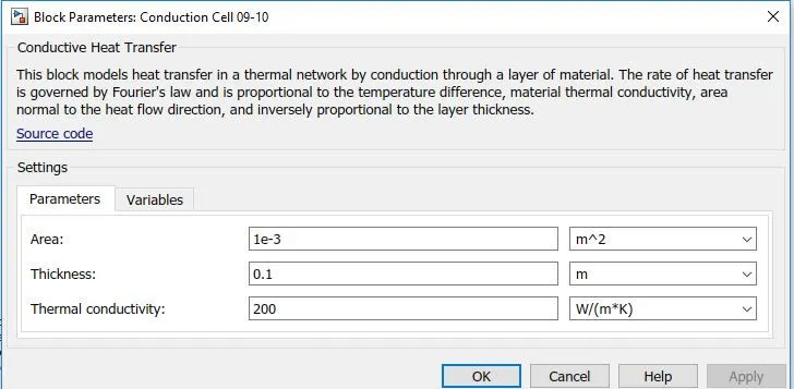
3.Conductive heat transfer :

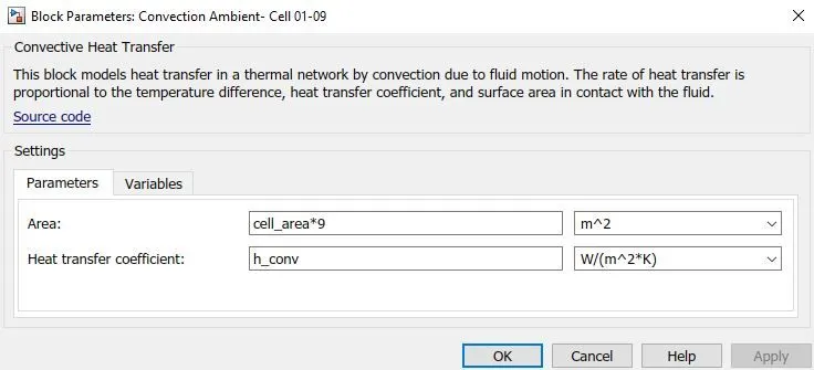
4.Convective heat transfer :

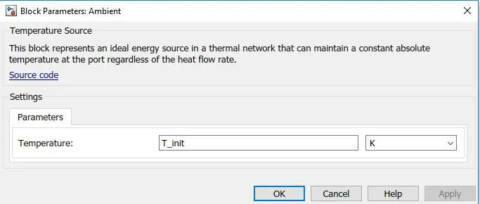
5.Temperature source:

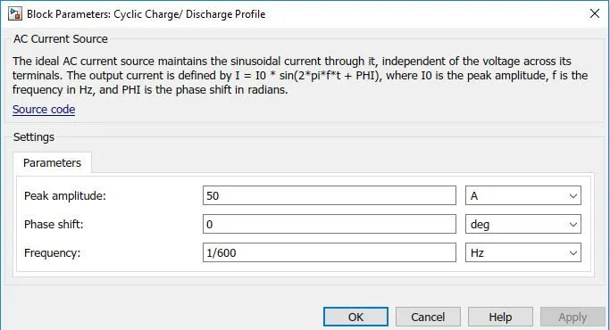
6.AC current source :

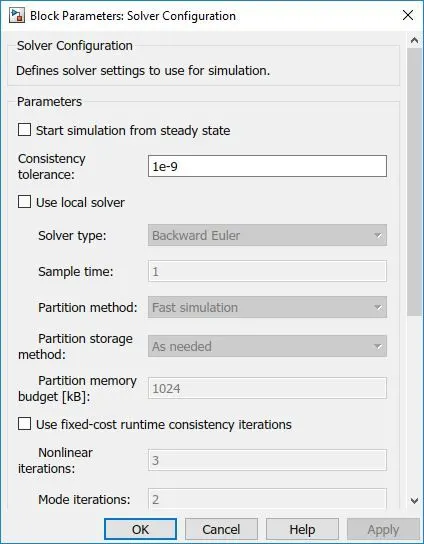
7. Solver configuration :

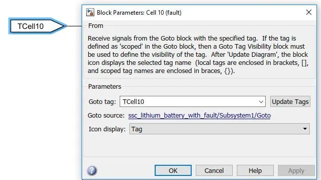
8. From : Which links to the Cell subsytem :
9.Mux :
Cell 01 to 04 :
Lithium Cell 1RC Subsystem
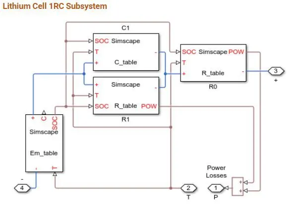
This block basically consists of capacitance value table which depends on an external physical signal inputs SOC and T. It is assumed that the capacitance value is slowly varying with time, and hence the equation i = C*dv/dt holds.
Resistance value (R) table which depends on an external physical signal inputs SOC and T.
Voltage value (EM) which implements the cell's main branch voltage source, and determines values for capacity (C) and state of charge (SOC). The defining equations depend on cell temperature, T.
The default model been modified :
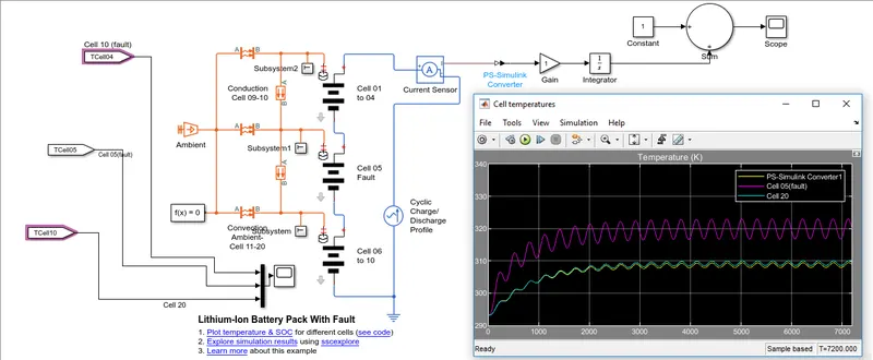
Here the output of one cell is connected with the SOC calculation whereas other output is connected with AC current source for cyclic charge/discharge profile.
Result :
We have cell temperature view, where the ambient temperature is set to be 293.15K :
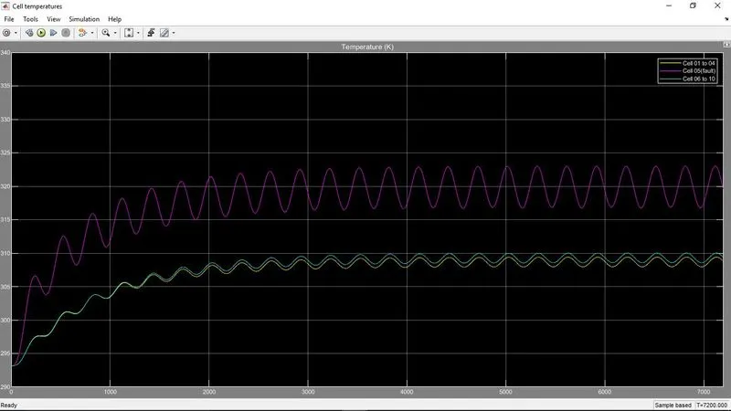
tried to set the temperature of lithium battery cell 01 to 04 as 295K;
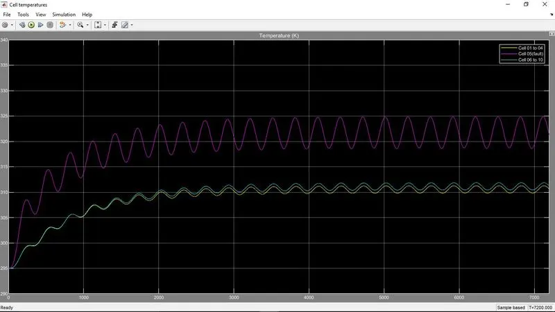
tried to set the temperature of lithium battery cell 06 to 10 as 310K
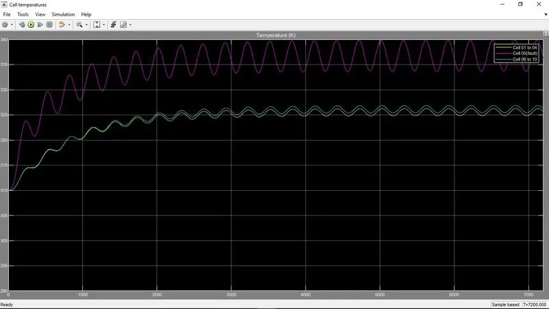
as from the above result we can identify that the Faulty Cell 5 showing wide temperature diff in comparison to the other cells temperature.