Project 2 Thermal modeling of battery pack
Project 2 Thermal modeling of battery pack
For a 10 cell series lithium ion battery model, simulate the thermal effects and compare life cycle performance at various temperatures, charge & discharge rates using MATLAB.
Below are the details of battery used for simulation:
Battery data:-
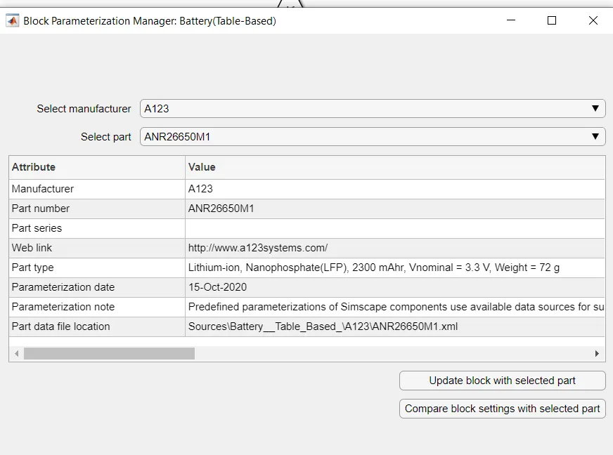
ANR26650M1 battery is used to simulate which was included in simulink.
The selection of battery and data are as shown below
Model:-
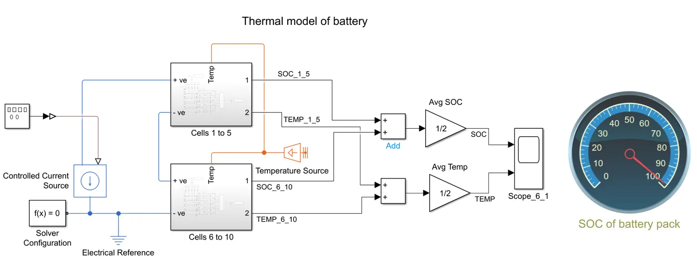
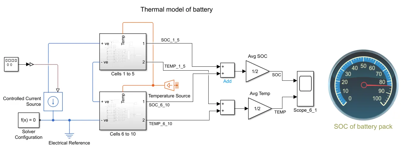
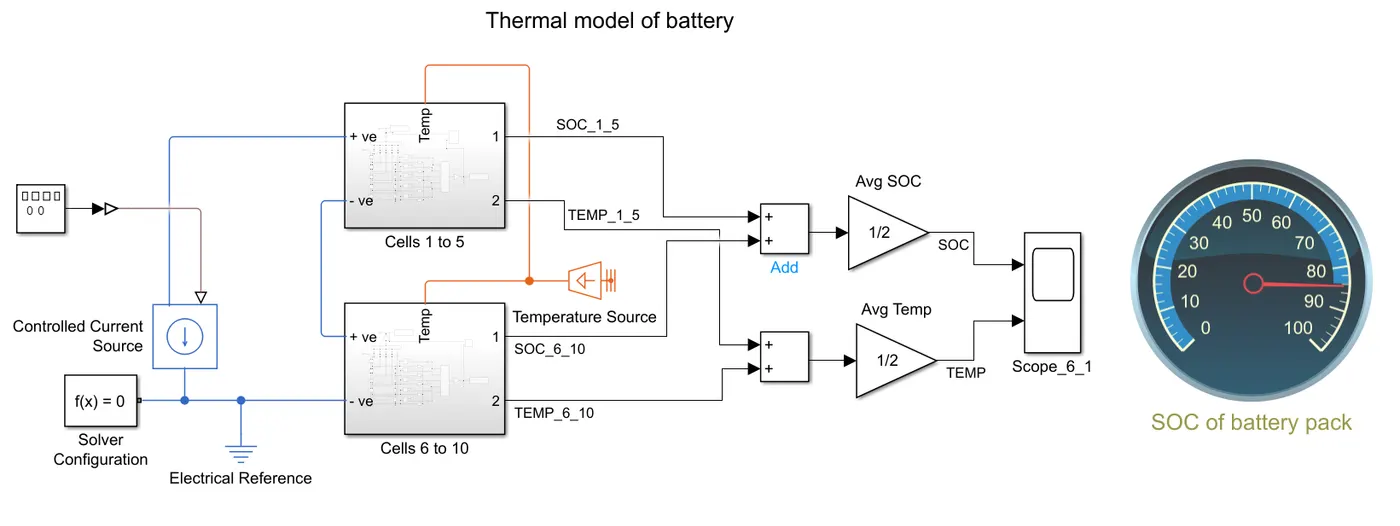
Thermal model of battery simulink model is as shown in above image
This model consists of
Ø Square wave generator:- To generate square wave and provide the input to the model.
Ø PS-Simulink converter:- This block is used to convert physical signal into simulink signal
Ø Controlled current source:- This block receives the input from square wave generator and gives output in the physical port which goes to the battery module.
Ø Cells 1 to 5 and Cells 6 to 10 :- These two are battery modules connected in the series and each module contains 5 batteries connected in series and the output of SOC and Temp are connected to the scope for analysis.
Ø Temperature source:- This block maintains the temperature constant at the port regardless of the heat flow rate.
Ø Scope:- Scope are used to analyse the result of the SOC and Temperature.
Ø Add:- This block is used to average the value of battery modules.
Ø SOC of battery pack:- This is used to display the SOC of battery pack.
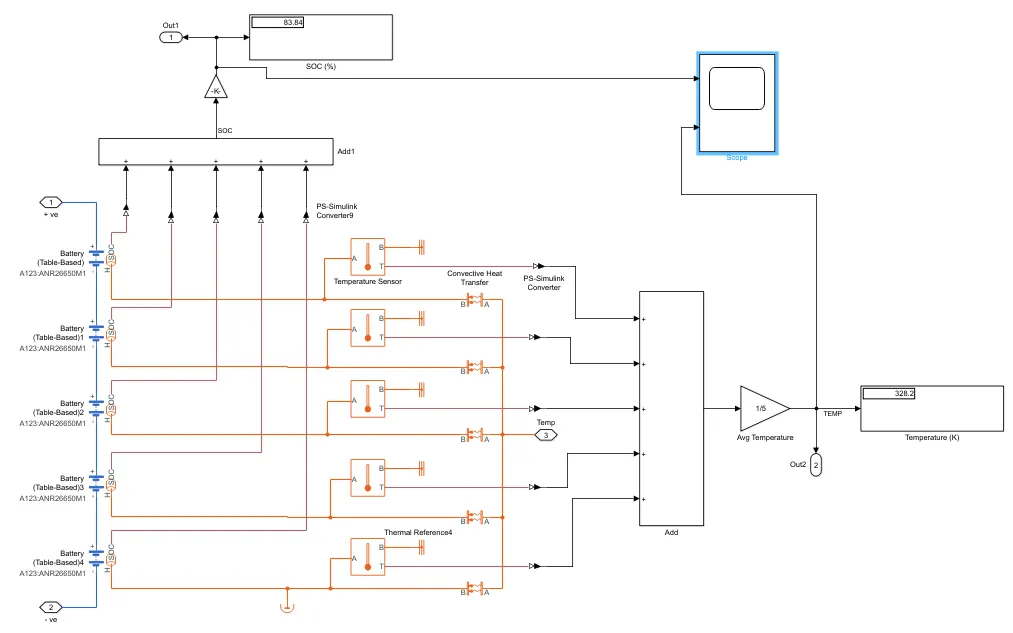
Module 1 = Cells 1 to 5 with convective heat transfer :-
Module 2 = Cells 6 to 10 with conductive heat transfer :-
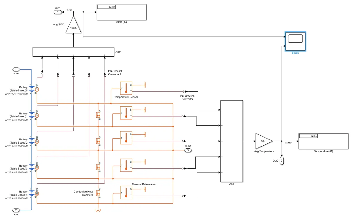
The above model represents the battery module with 5 batteries connected in series.
Ø Battery (Table based):- This block is used to simulate the battery characteristics and behaviour of the battery with the thermal effects.
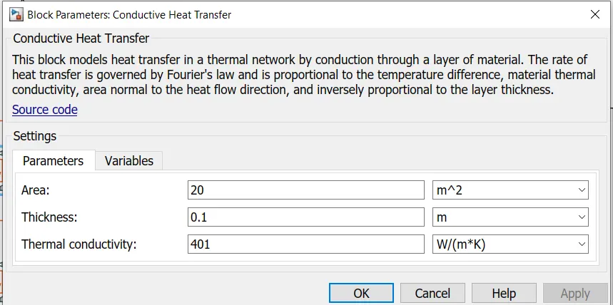
Ø Conductive heat transfer:- This block transfers the heat using conduction method. The values used to simulate the model are as in below image.
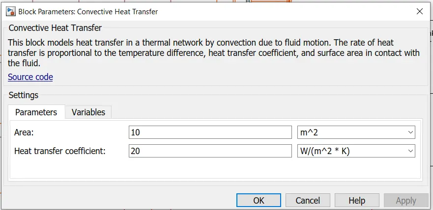
Ø Convective heat transfer:- This block transfers the heat using convection method. The values used to simulate the model are as in below image.
Ø Temperature sensor is used to sense the temperature of the battery.
Ø Display is used to display the SOC and temperature.
Result:
Case 1:-
Temperature = 30oC:
Simulation time = 3600 sec
Current rate = 0.5C
|
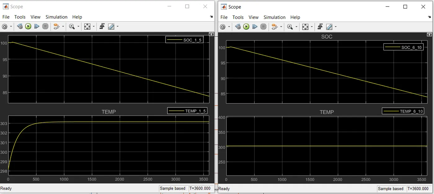
SOC and Temperature of module 1 [%]: |
SOC and Temperature of module 2 [%]: |
|
|
|
|
Module 1 has convective heat transfer and module 2 has conductive heat transfer. The temperature increases gradually from 298K to 303K and becomes constant in module 1. Temperature is constant I.e. 303K in module 2. |
|
|
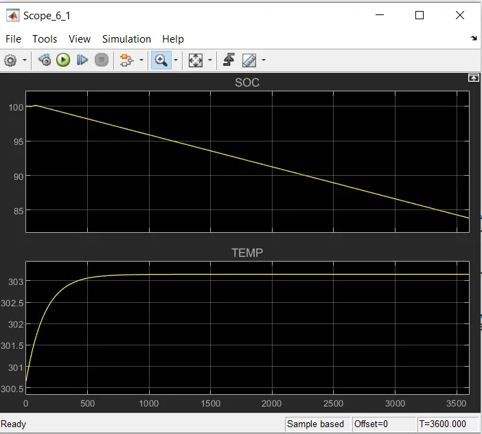
SOC and Temperature of battery pack [%]: |
|
|
|
|
|
Temperature starts from near to 300.7 K and stops above and near to 303.3 K. SOC starts from 100% to below and near to 84%. |
|
|
Dashboard result |
|
|
|
|
|
The final SOC I.e. after simulation of 3600 sec is near to 84% |
|
Case 2:-
Temperature = 55oC:
Simulation time = 3600 sec
Current rate = 0.5C
|
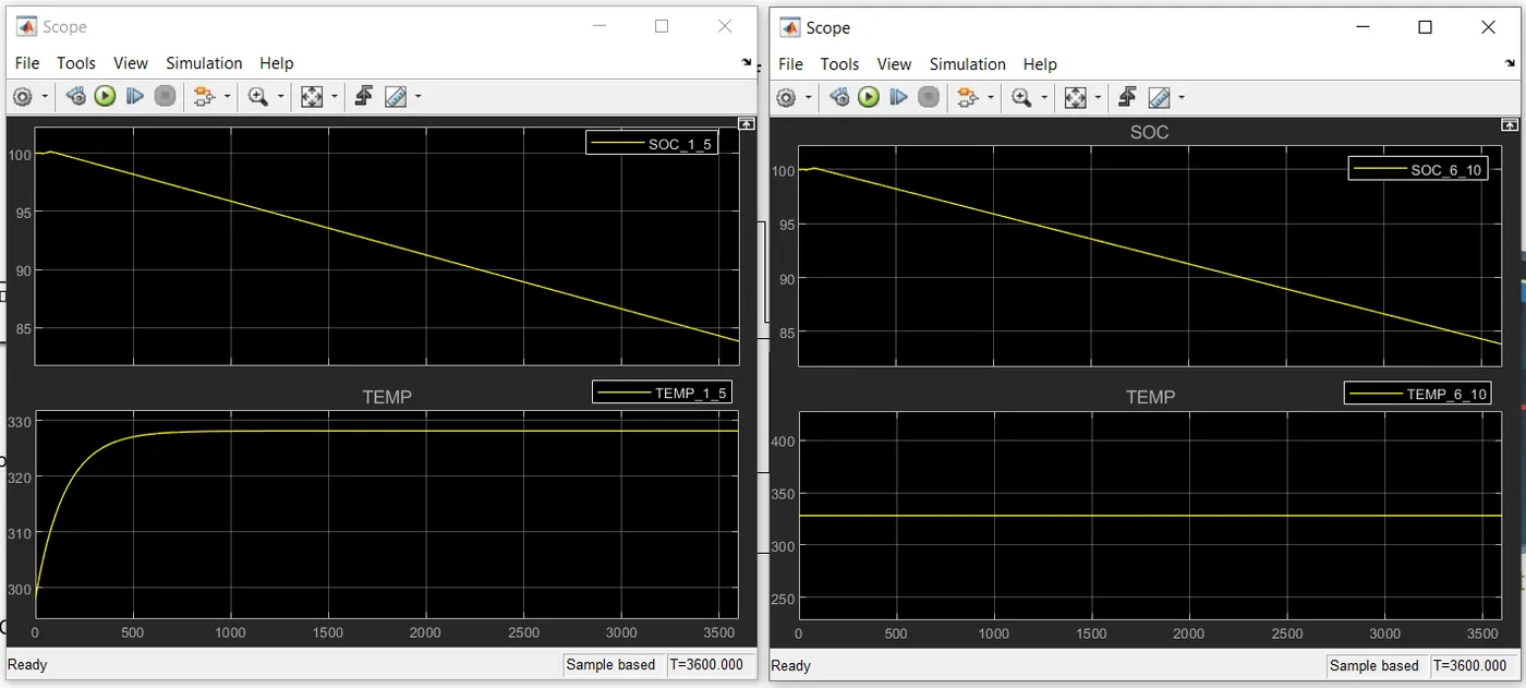
SOC and Temperature of module 1 [%]: |
SOC and Temperature of module 2 [%]: |
|
|
|
|
Module 1 has convective heat transfer and module 2 has conductive heat transfer. The temperature increases gradually from 299K to 330K and becomes constant in module 1. Temperature is constant I.e. 330K in module 2. |
|
|
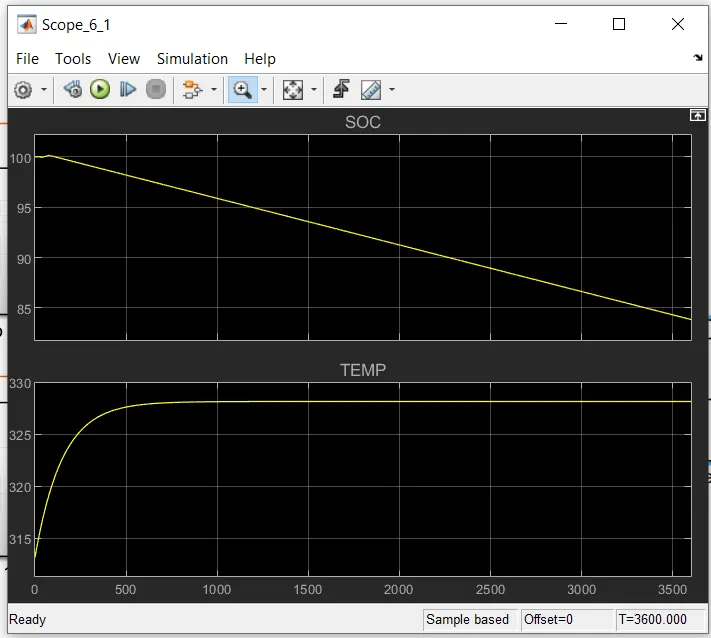
SOC and Temperature of battery pack [%]: |
|
|
|
|
|
Temperature starts from near to 299 K and stops above and near to 330 K. SOC starts from 100% to below and near to 84%. |
|
|
Dashboard result |
|
|
|
|
|
The final SOC I.e. after simulation of 3600 sec is below 84% |
|
Conclusion:-
Hence this shows that temperature do not affect the SOC.