Thermal modeling of battery pack
Aim: Thermal modelling of the battery pack.
Objective: Simulating battery pack of 10 cells in series and plot for thermal effects and SOC of the battery pack.
Theory:
The battery temperature should be controlled within temperature limits to avoid thermal issues and improve performance. The temperature range affects the battery power and battery cycle life. At the same time, the temperature distribution should be even to guarantee the battery performance. That is also the reason why the battery thermal management system is necessary to the battery system. In addition, the uneven temperature distribution is another problem of batteries. Typically, it is caused by the excessive local temperature, variable current in a cell and the thermal conductivity of the case, as well as the placement of positive and negative terminals and so on.
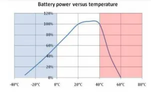
When temperature ranges from 20°C to 40°C, battery power reaches maximum
Generally, the temperature must be controlled between 20°C and 40°C to ensure performance and cycle life. Moreover, the temperature distribution is controlled under 5K to keep the safety and lifetime of the battery. In addition, ventilation is also essential to the battery system and should be taken into account.
Battery Thermal Management Systems (BTMS):
The BTMS should be equipped with four essential functions to ensure the right operation conditions of the battery pack:
1. Cooling: Due to inefficiency, battery cells will not only generate electricity but also heat. This heat should be moved from the battery pack when the battery temperature reaches the optimum temperature or even in advance. Thus, a cooling function is required in BTMS.
2. Heating: In cold climates, battery pack temperature probably falls below the lower temperature limit. Hence, a heating function, such as a PTC heater, is required to assist the battery pack to reach the proper temperature range in a shorter time.
3. Insulation: In extreme cold or hot weather, the temperature difference between the inside and outside of the battery pack is much larger than that in mild weather. Battery temperature will thus fall (cold) or rise (hot) sooner out of the proper temperature range. To prevent this, good insulation can slow down the falling
or rise of battery temperature, especially when the vehicle is parked outdoors.
4. Ventilation: Ventilation is required to exhaust the hazardous gases within the battery pack. In some systems, such as air systems, this function is combined with cooling and heating functions.
The battery thermal management system (BTMS) plays a vital role in the control of the battery thermal behaviour. The BTMS technologies are air cooling system, liquid cooling system, direct refrigerant cooling system, phase change material cooling system, and thermo-electric cooling system as well as heating.
Air Cooling and Heating:
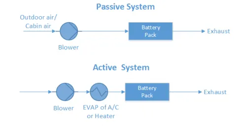
Air systems use air as the thermal medium. The intake air could be direct either from the atmosphere or from the cabin and could also be conditioned air after a heater or evaporator of an air conditioner. The former is called a passive air system and the latter is an active air system. Active systems can offer additional cooling or heating power. A passive system can offer hundreds of watts of cooling or heating power and active system power is limited to 1 kW.
Liquid Cooling and Heating:
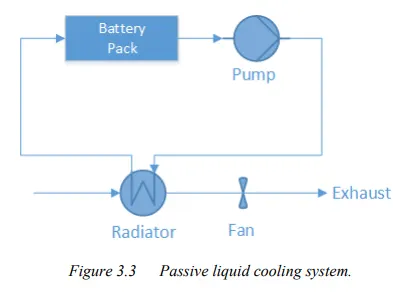
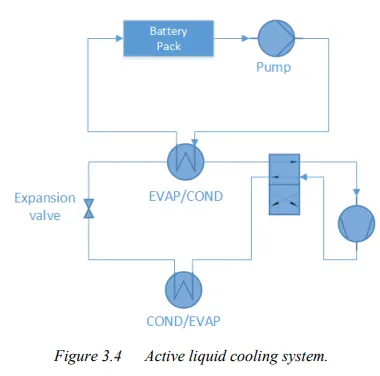
By different heat-sinks for cooling, liquid systems can also be categorized into either passive systems or active systems. In a passive liquid system, the heat sink for cooling is a radiator. This system has no ability to heat. The figure below presents the systematic scheme of a passive liquid system. Heat transfer fluid is circulated by the pump within a closed system. The circulating fluid absorbs heat from the battery pack and releases heat via a radiator. In an active system, there are two loops. The upper is called the primary loop and the lower the secondary loop. The primary loop is similar to the loop in a passive liquid system, where the heat transfer fluid is circulated by the pump. The secondary loop is actually an air conditioning loop.
Direct Refrigerant Cooling and Heating:
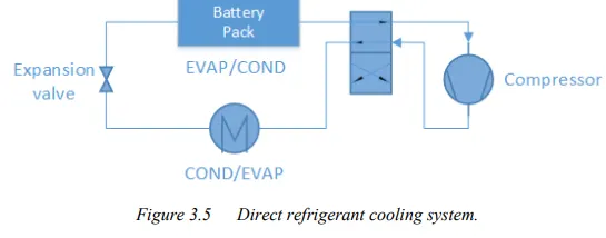
Similar to active liquid systems, a direct refrigerant system (DRS) consists of an A/C loop, but DRS uses refrigerant directly as heat transfer fluid circulating through the battery pack. The systematic layout is in Figure.
PCM:
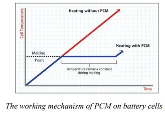
During melting, heat is absorbed by PCM and is stored as latent heat until the latent heat is up to the maximum. The temperature is kept at the melting point for a period and the temperature increase is delayed. Therefore, PCM is used as a conductor and buffer in battery thermal management systems. Also, a PCM is always combined with an air cooling system or liquid cooling system to manage the battery temperature.
Thermo-electric Module:
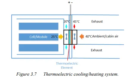
The thermoelectric module can convert electric voltage to temperature difference and vice versa. Here the former effect is adopted. That means it transfers heat through the module by consuming electricity directly. Two fans are installed to improve heat transfer by forced convection. To combine a passive air system with the thermoelectric module, the combined system is able to cool down the battery even lower than the intake air temperature.
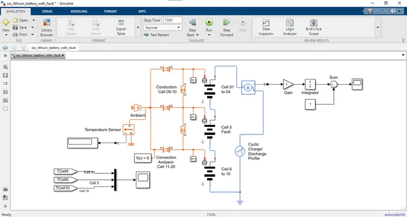
Simulink model of 10 cells in series:
Explanation:
Cell 1-4 subsystem:
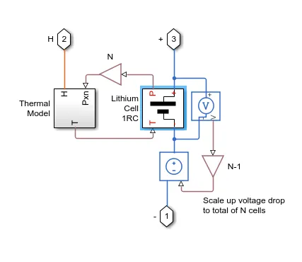
- In 1-4 cells we have the thermal model and lithium-ion 1RC block which calculates the overall battery pack temperature and thermal effects.
- The PS Gain block performs element-wise multiplication of the input physical signal by a constant value
y = u .* gain.
- The Voltage Sensor block represents an ideal voltage sensor, that is, a device that converts voltage measured between two points of an electrical circuit into a physical signal proportional to the voltage.
-
The current-voltage source block represents an ideal voltage source that is powerful enough to maintain the specified voltage at its output regardless of the current passing through it. The output voltage is V = Vs, where Vs is the numerical value presented at the physical signal port.
Thermal model:
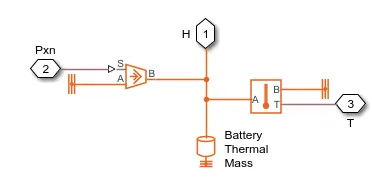
In the 1-4 cell subsystem the main block is a thermal model block:
- Thermal reference block: The Thermal Reference block represents a thermal reference point, that is, a point with an absolute zero temperature, with respect to which all the temperatures in the system are determined.
- controlled heat flow rate source: The Controlled Heat Flow Rate Source block represents an ideal source of thermal energy that is powerful enough to maintain specified heat flow at its outlet regardless of the temperature difference across the source.
- Battery thermal mass: The Thermal Mass block represents a thermal mass, which reflects the ability of a material or a combination of materials to store internal energy. The property is characterized by the mass of the material and its specific heat.
- Temperature sensor: The Temperature Sensor block represents an ideal temperature sensor, that is, a device that determines the temperature differential measured between two points without drawing any heat.
Lithium-ion 1RC:
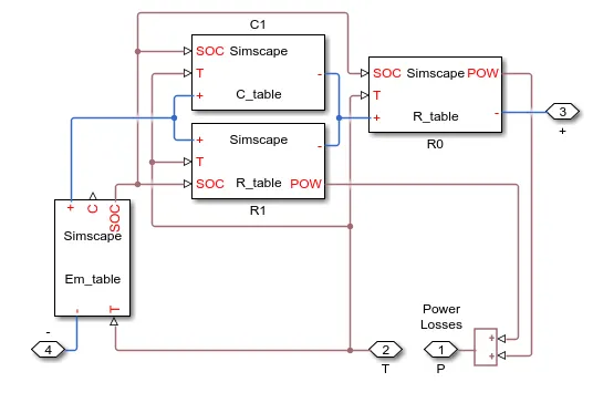
- In lithium-ion 1RC block, C1 is the capacitance which is dependent on an external physical signal inputs SOC and T. It is assumed that the capacitance value is slowly varying with time, and hence the equation i = C*dv/dt holds.
- R1 block represents a resistor where the resistance value (R) depends on an external physical signal inputs SOC and T.
- The Em_table block implements the cell's main branch voltage source and determines values for capacity (C) and state of charge (SOC). The defining equations depend on cell temperature, T.
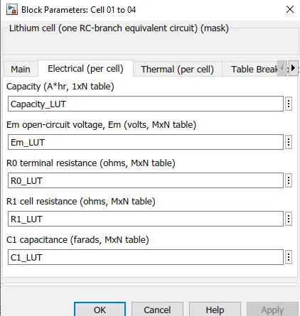
Cell 1-4:
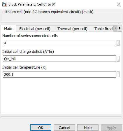
- All cells are connected in series (4 cells).
- Initially, the temperature of the cell is 299.1K.
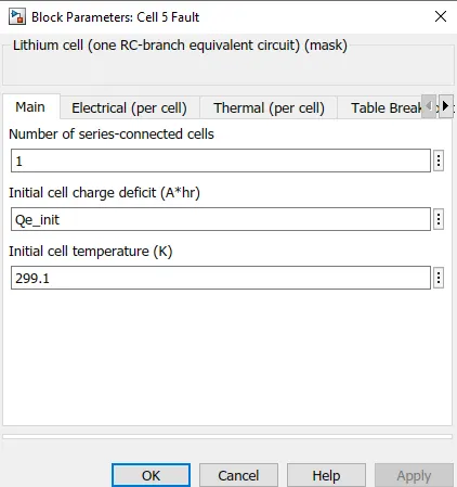
Cell 5(Default):
- Cell connected is the default.
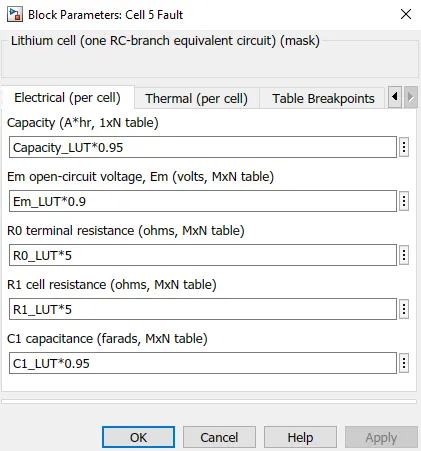
- Here the capacity is 95% of the total capacity instead of 100%
- Open circuit voltage is taken as 90% out of 100%.
- All the resistance value is taken as 50% and capacitance as 95%.
- These all values are taken so that this cell should act as a default cell.
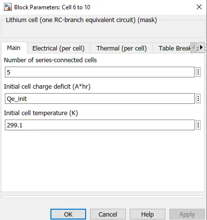
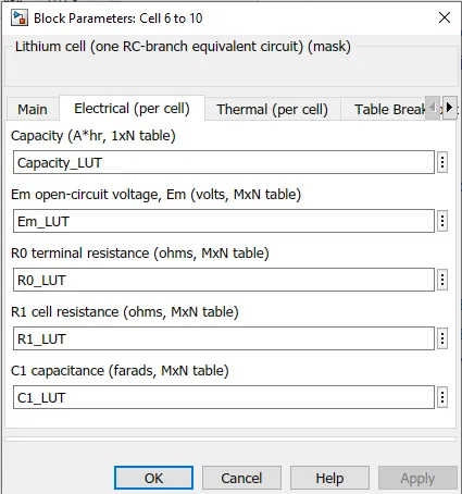
Cell 6-10:
- All cells are connected in series (5 cells).
- The initial temperature is 299.1K.
Cyclic charge/discharge profile:
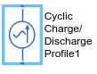
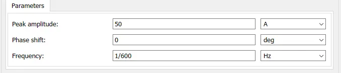
The ideal AC current source maintains the sinusoidal current through it, independent of the voltage across its terminals. The output current is defined by I = I0 * sin(2*pi*f*t + PHI), where I0 is the peak amplitude, f is the frequency in Hz, and PHI is the phase shift in radians.
Temperature source:

The temperature source block represents an ideal energy source in a thermal network that can maintain a constant absolute temperature at the port regardless of the heat flow rate.

Convection heat transfer:

The convective heat transfer block models heat transfer in a thermal network by convection due to fluid motion. The rate of heat transfer is proportional to the temperature difference, heat transfer coefficient, and surface area in contact with the fluid.

Conductive heat transfer:
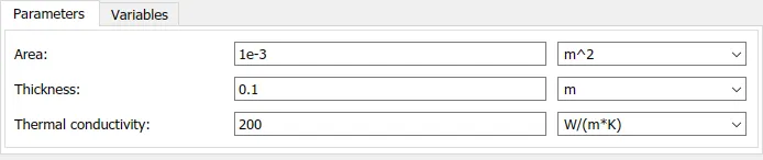
The conductive heat transfer block models heat transfer in a thermal network by conduction through a layer of material. The rate of heat transfer is governed by Fourier's law and is proportional to the temperature difference, material thermal conductivity, area normal to the heat flow direction, and inversely proportional to the layer thickness.
Result:
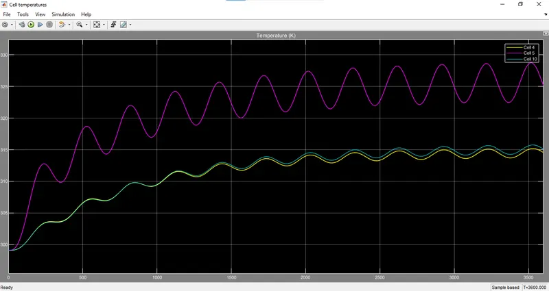
For same temperature:
- Ambient tempertaure=299.1K
- Cell 1-4 = 299.1K
- Cell 5 = 299.1K
- Cell 6-10 = 299.1K
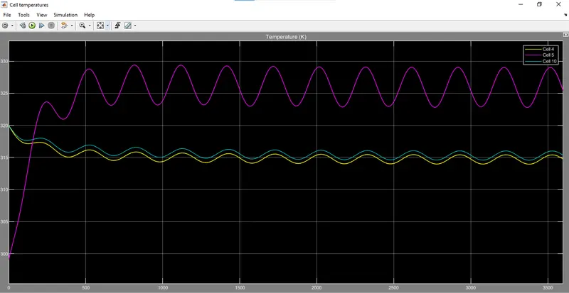
For minimum default cell temperature:
- Ambient tempertaure=299.1K
- Cell 1-4 = 320K
- Cell 5 = 299.1K
- Cell 6-10 = 320K
Output:
For Maximum default cell temperature:
- Ambient tempertaure=299.1K
- Cell 1-4 = 320K
- Cell 5 = 350K
- Cell 6-10 = 320K
Output:

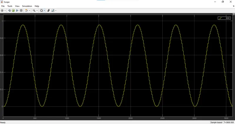
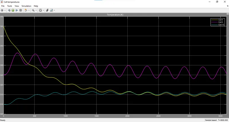
For high to low tempertaure:
- Ambient tempertaure=299.1K
- Cell 1-4 = 350K
- Cell 5 = 325K
- Cell 6-10 = 310K
Output:
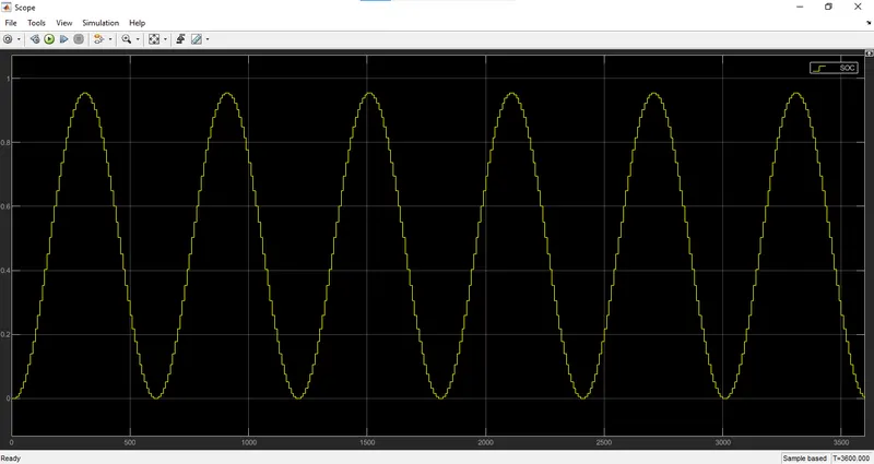
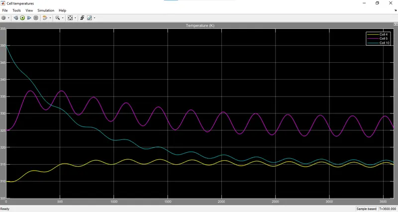
For low to high temperature:
- Ambient tempertaure=299.1K
- Cell 1-4 = 310K
- Cell 5 = 325K
- Cell 6-10 = 350K
Output:
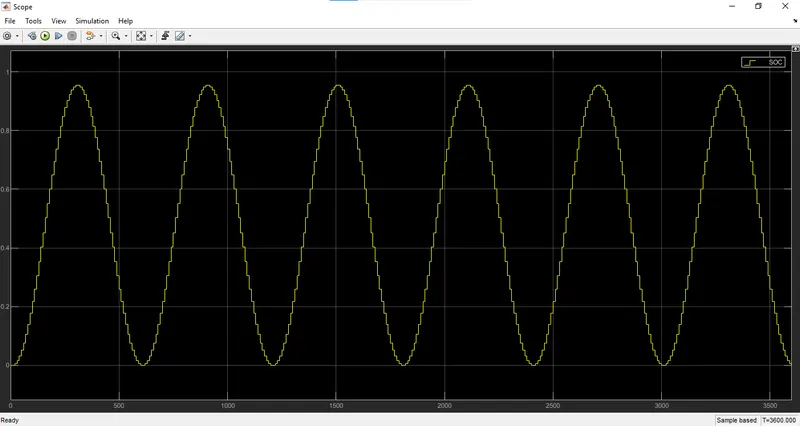
Result:
| Sr.No | Ambient temperature(K) | Cell 1-4 tempertaure(K) | Cell 5 temperature(K) | Cell 6-10 temperature(K) | SOC | Condition |
| 1. | 299.1 |
Start:299.1 End:314 |
Start:299.1 End:325 |
Start:299.1 End:315 |
Start:0 End:0 Peak:90% |
When all the temperatures are the same |
| 2. | 299.1 |
Start:320 End:315 |
Start:299.1 End:325 |
Start:320 End:315 |
Start:0 End:0 Peak:90% |
When the default cell temperature is minimum. |
| 3. | 299.1 |
Start:320 End:315 |
Start:350 End:325 |
Start:320 End:315 |
Start:0 End:0 Peak:90% |
When the default cell temperature is maximum. |
| 4. | 299.1 |
Start:350 End:315 |
Start:325 End:324 |
Start:310 End:315 |
Start:0 End:0 Peak:90% |
When the cell temperature increases from high to low. |
| 5. | 299.1 |
Start:310 End:315 |
Start:325 End:325 |
Start:350 End:315 |
Start:0 End:0 Peak:90% |
When the cell temperature increases from low to high. |
For UDDS cycle as input:
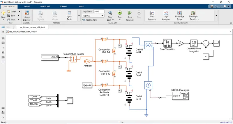
Here the input in signal builder block by giving time and current input of UDDS cycle in the workspace and by customizing that signal in signal builder block.
Output:
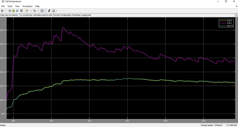
- In this plot, we can observe the temperature of cell 1-4 is increasing from 293.1K its initial temperature and attends the peak value up to 293.125K and gets settled at 293.12K.
- The cell temperature of 5 starts increasing from 293.11K and attends the peak temperature of 293.16K and settles at 293.15K.
- The cell temperature of 6-10 starts from 293.1K and attends the peak temperature of almost the same as that of 1-4 cell 293.125K and settles as same as that of 1-4 cell at 293.12K.
- Cell 1-4 and cell 6-10 behaviour is almost the same.
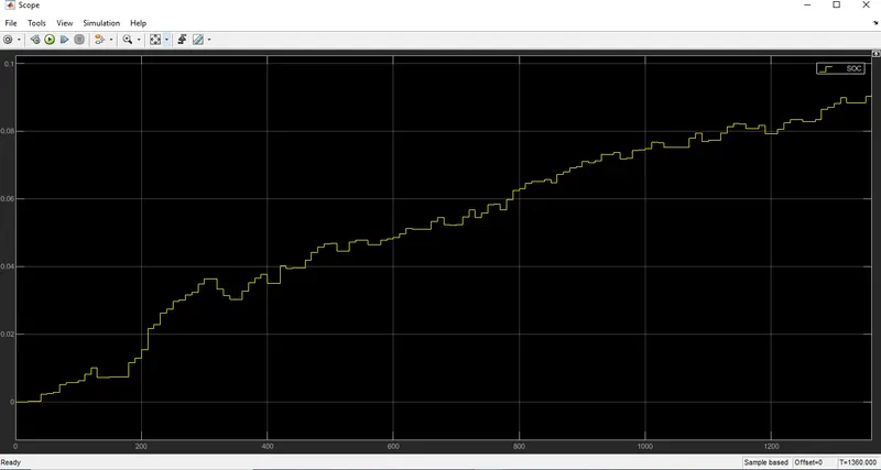
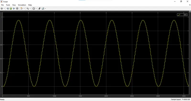
- Here in this SOC plot, we can observe that charge and discharge are in step form as this is because when speed increases the plot goes up and when there is standby mode the signal is constant and when there is charging mode the signal goes down.
- After the battery has run for 1369 sec it got discharged up to 0.9 which means 90%.
Conclusion:
- Simulated 10 cell series lithium ion battery model.
- Results are in temperatures and SOC.
- Thermal effects of cells are plotted.