Project 2 Thermal modeling of battery pack
AIM-
Preparing a 10 cell series lithium ion battery pack simulating its thermal effect and comparing its life cycle performance and charge and discharge rates.
INTRODUCTION
Lithium ion battery
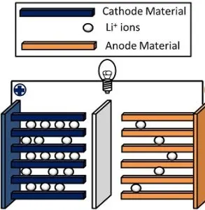
A lithium-ion (Li-ion) battery is an advanced battery technology that uses lithium ions as a key component of its electrochemistry. During a discharge cycle, lithium atoms in the anode are ionized and separated from their electrons. The lithium ions move from the anode and pass through the electrolyte until they reach the cathode, where they recombine with their electrons and electrically neutralize. The lithium ions are small enough to be able to move through a micro-permeable separator between the anode and cathode. In part because of lithium’s small size (third only to hydrogen and helium), Li-ion batteries are capable of having a very high voltage and charge storage per unit mass and unit volume.
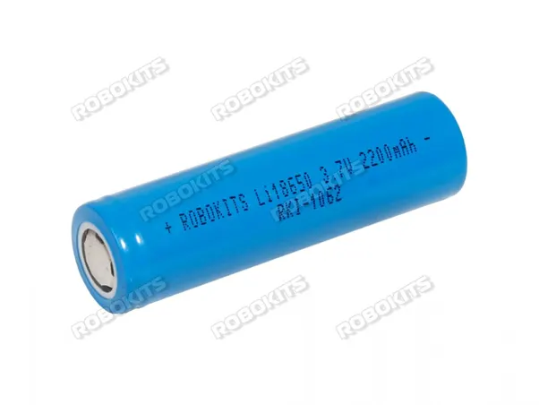
Li-ion batteries can use a number of different materials as electrodes. The most common combination is that of lithium cobalt oxide (cathode) and graphite (anode), which is most commonly found in portable electronic devices such as cellphones and laptops. Other cathode materials include lithium manganese oxide (used in hybrid electric and electric automobiles) and lithium iron phosphate. Li-ion batteries typically use ether (a class of organic compounds) as an electrolyte.
Thermal effects of the lithium ion battery
Temperature is known to have a significant impact on the performance, safety and cycle lifetime of lithium-ion batteries. However, the comprehensive effects of temperature on the cyclic aging rate of Li ion Battery have yet to be found. We use an electrochemistry-based model (ECBE) here to measure the effects on the aging behavior of cycled Li ion battery operating within the temperature range of 25 °C to 55 °C. The increasing degradation rate of the maximum charge storage of Li ion Battery during cycling at elevated temperature is found to relate mainly to the degradations at the electrodes and that the degradation of LCO cathode is larger than graphite anode at elevated temperature. In particular, the formation and modification of the surface films on the electrodes as well as structural/phase changes of the LCO electrode, as reported in the literatures, are found to be the main contributors to the increasing degradation rate of the maximum charge storage of Li ion Battery with temperature for the specific operating temperature range. Larger increases in the Warburg elements and cell impedance are also found with cycling at higher temperature, but they do not seriously affect the state of health (SoH) of Lithium ion battery.
Charge and discharge rates of Lithium ion battery-
Lithium ion batteries charge and discharge rate determine the speed of how fast we can storage certain amount of energy into battery inside, or how fast release the inside energy of the battery. Of course, the storage and release process is controllable and safe, which will not significantly affect the service life of battery and other performance indicators.
Simulink model of battery pack to simulate its thermal effect
Main model-
Working principle and model explanation-
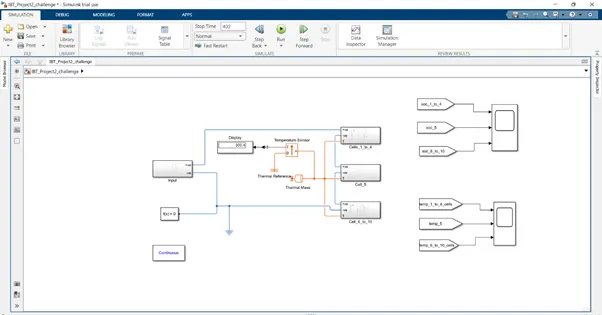
There are three subsystems in this model as we can see. The input subsystem has connected with the battery to giving the input. It has also connected with solver configuration for specifies the solver parameters and the electrical reference which gives the ground connection to this circuit. Even it is connected with temperature sensor to sense the temperature of the circuit and showing in display block. Thermal mass block models the internal energy storage in thermal network. The power gui block maintain the circuit. And the last one there is two scope blocks which is showing the result of simulation, this block represents the SoC and thermal effect of the battery which is coming through the from block.
Input subsystem-
Working principle and model explanation-
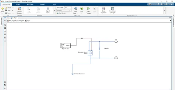
This subsystem is giving the input to the battery. In this subsystem we entered the input in signal builder and through the Simulink ps converter the inputs has converted to physical signal from Simulink signal, and this input is current which is controlled by the controlled current source block. As we know the electrical reference gives ground connection to the circuit. The resistor derives some resistance to this circuit and there are two port connectors which represents the positive and negative terminal of this subsystem.
1 to 4 cell subsystem-
Working principle and model explanation-
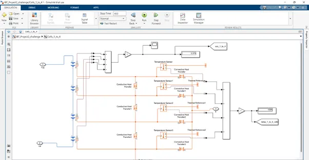
In this subsystem there are four table based cells. Each cell has connected with convective heat transfer and temperature sensor block, convective heat transfer block models heat transfer in thermal network by convection due to fluid motion and it senses the temperature by the temperature sensor block. The thermal reference block represents a reference point in a thermal network where temperature is equal to absolute zero. There are three conductive heat transfer blocks, it models heat transfer in this thermal network by conduction through a layer of material. The perfect insulator block represents a terminus in this thermal network circuit with no heat flow and no energy storage. The adder block add the SoC of all four cells through the gain and display its value in display block and showing its graph in scope. And one adder block add the temperature value which is coming from temperature sensor and displaying in display block. The port connector block represents its positive and negative connection.
Cell 5 subsystem-
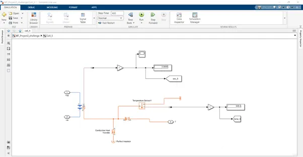
As we discussed in Cell 1 to 4 subsystem this block has same concept. The difference is there is all single block for simulation of this subsystem.
6 to 10 cell subsystem-
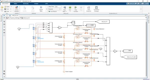
As we discussed in Cell 1 to 4 subsystem this block has same concept. The difference is there is one more battery, conductive heat transfer, convective heat transfer, temperature sensor and the thermal reference block and rest is same working concept.
SoC scope-
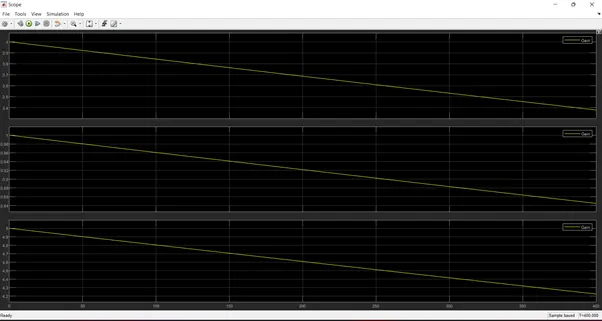
In this simulation results the SoC is decreasing in 400 seconds with respect to increasing temperature. When the temperature increases then battery is going to discharge fastly.
Temperature scope-
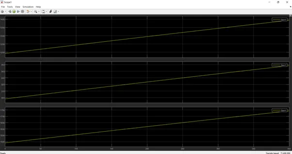
Thus from this simulation result first one is cell 1 to 4 second one is cell 5 and the third one is cell 6 to 10. It represents the thermal effect of the battery pack of each subsystem. First one have four cells it represents in 400 seconds the temperature goes on upto 1400K. The second one is cell 5 it represents in 400 seconds temperature goes upto 300K. the third one represents in 400 seconds the temperature upto 1750K.
The cyclic charge and discharge profile means it can AC Current sources, which charges and discharges the battery by sending the alternating current on a time basis and it has a time period.