Project 2 Thermal modeling of battery pack
Aim: For a 10 cell series lithium ion battery model simulate the thermal effects and compare life cycle performance at various temperatures charge & discharge rates using MATLAB.
Answer:
About the lithium ion battery:
The lithium-ion battery or Li-ion battery is a type of rechargeable battery which is composed of cells in which lithium ions move from the negative electrode through an electrolyte to the positive electrode during discharge and back when charging.
- The Lithium-ion batteries are divided into various kinds according to size form the material used for the positive and negative electrodesand so on.
- The industrial lithium-ion battery uses lithium titanium oxide on the negative electrode and provides a long life rapid charging high input/output power performance excellent low-temperature operation and a wide effective SOC range
- The lithium-ion battery are composed of
- 1) the anode and the cathode
- 2) a separator between the two electrodes
- 3) an electrolyte that fills the remaining space of the battery.
- In The anode and cathode are capable of storing lithium ions.
- The Energy is stored and released as lithium ions travel between these electrodes through the electrolyte
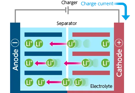
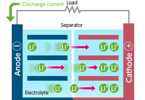
In charging :
- The charger passes current to the battery
- Lithium ions move from the cathode to the anode through the electrolyte
- The battery is charged by a potential difference between the two electrodes.
- IN discharging:
- A discharge circuit is formed between the anode and the cathode.
- Lithium ions stored in the anode move to the cathode.
- Energy is used.
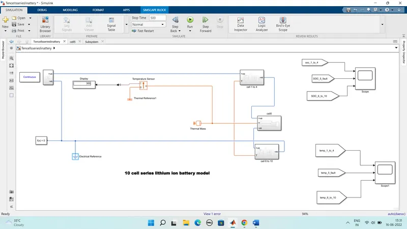
Simulink model forthe 10 cells series cinnected Lithium ion battery:
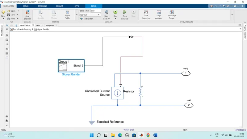
Subsystem of siginal builder block:
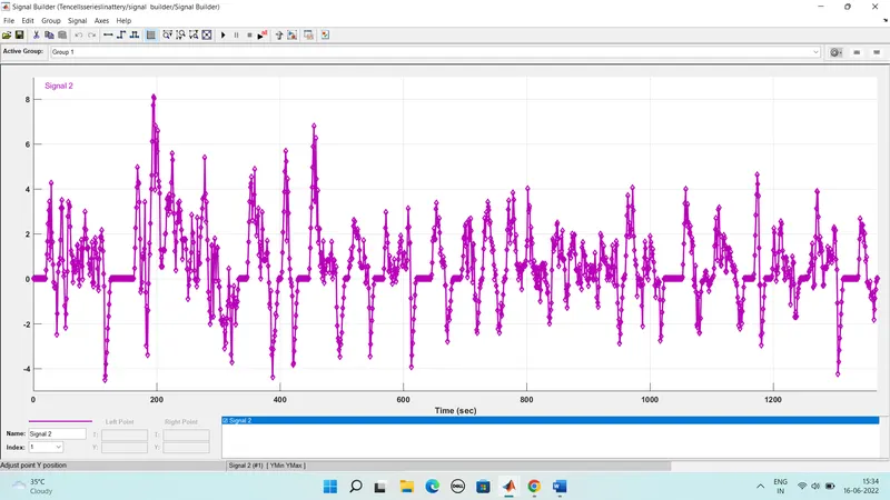
Now here we have different subsytems for group of cells
1) For cell 1 to 4 subsytem:
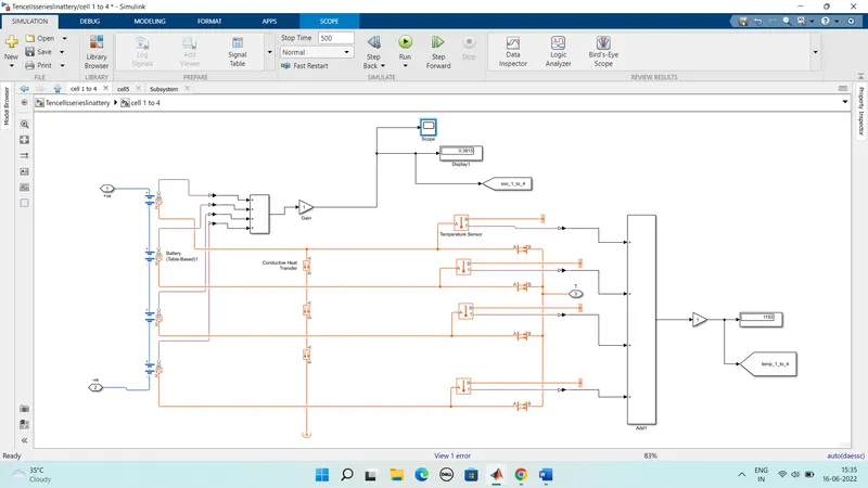
a)Table based battery:
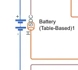
The Battery (Table-Based) block represents a high-fidelity battery model.
The block calculates no-load voltage as a function of charge level and optional temperature using lookup tables and includes several modeling options:
Self-discharge
Battery fade
Charge dynamics
Calendar aging
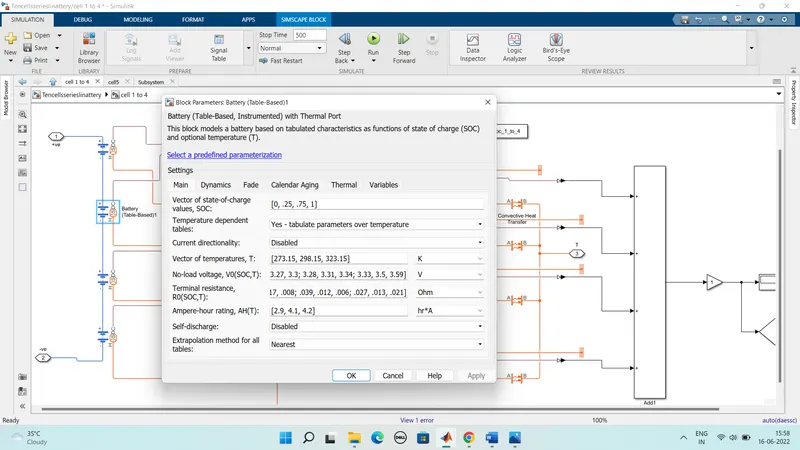
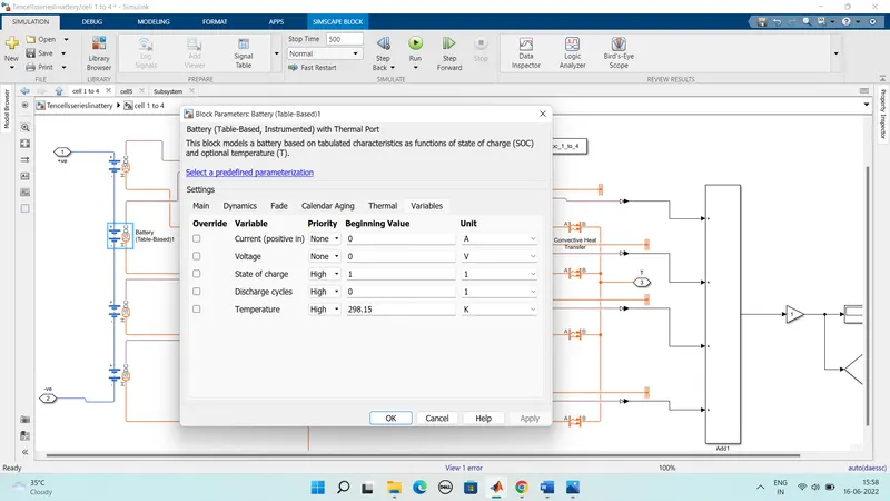
Here we are used the default values for the table based battery
b) conductive heat transfer:
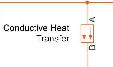
The Conductive Heat Transfer block represents a heat transfer by conduction between two layers of the same material. The transfer is governed by the Fourier law and is described with the following equation:
Q=k·A/D(TA−TB)
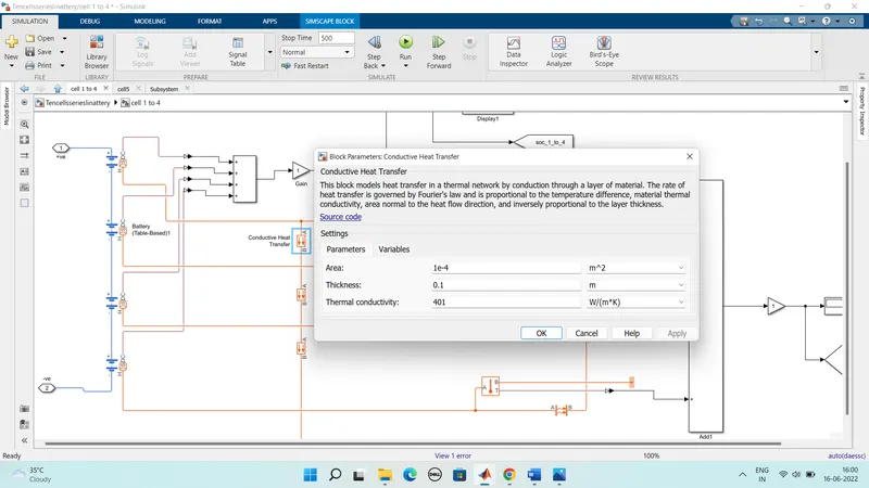
In this block model mainly the heat transfer in a thermal network by conduction through a layer of material.
The rate of heat transfer is governed by Fourier's law and is proportional to the temperature difference material thermal conductivity area normal to the heat flow direction and inversely proportional to the layer thickness
c)Temperature senso
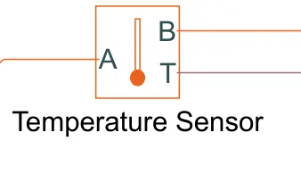
The Temperature Sensor block represents an ideal temperature sensor that is a device that determines the temperature differential measured between two points without drawing any heat.
Connections A and B are thermal conserving ports that connect to the two points where temperature is being monitored.
Port T is a physical signal port that outputs the temperature differential value.
The block positive direction is from port A to port B. The measured temperature is determined as T = TA – TB.
d) Convective heat transfer:
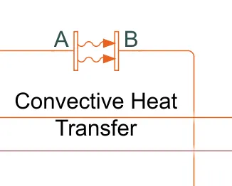
The Convective Heat Transfer block represents a heat transfer by convection between two bodies by means of fluid motion.
The transfer is governed by the Newton law of cooling and is described with the following equation:
Q=k·A·(TA−TB)
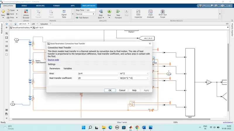
In this block mainly the model is a heat transfer in a thermal network by convection due to fluid motion.
Here the rate of heat transfer is proportinal to the temperature differance heat transfer coefficient and surface area in contact with the fluid.
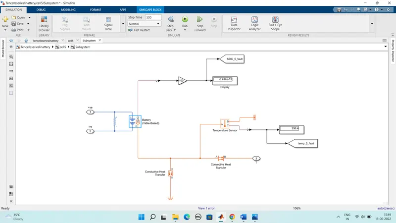
2) For cell 5
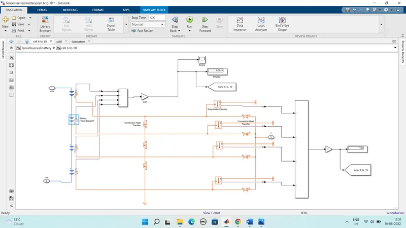
3) For cell 6 to 10 :
Model explanation:
- From the Above model we can see that the representation of the 10 cell series connection.
- The lithium-ion battery pack of 10 cells is used. In order to check for the thermal effects one of the cells is considered as faulty.
- The Fault in the sense that the temperature of this cell is higher than the other nine.
- So The battery is assumed to be air-cooled and provided with ventilators with ambient air and temperature.
- So For modeling this case we all the cells are connected with ambient temperature.
- Here The convective heat transfer from the surrounding to the cells and conductive between the cells is also modeled using there respective blocks.
- There are temperature sensor blocks which is used to detect the temperature from the cells.
- And The current drawn from the cells is controlled by the Controlled Current Source block.
- The data of a drive cycle in the form of a current is fed to this current controller.
- Here we used a signal builder block ito feed this drive cycle data and it is stored in the form of current vs time.
- Then After running the model SOC vs time and temperature vs time graphs are plotted.
Subsystem outputs:
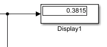
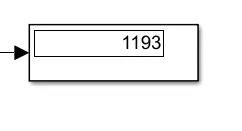
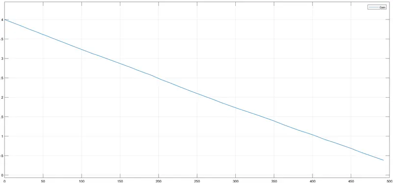
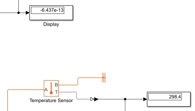
For cell 1 to 4
For cell 5 :
For cell 6 to 10 :
Final output results:
SOC state of charge results :
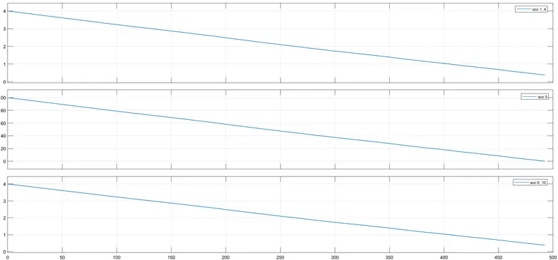
The above figure gives the various stages of state of charge results i.e cell 1 to 4 and 5 and aslo 6 to 10
Here the the Soc charge as been decreased rapidly in all the states i.e cell 1 to 4 ,5 and 6 to 10
In the cell 1 to 4 it decreases from 4% to 1.5% nearly
Similarly in cell 5 it decreases from 100%20%
In the cell 6-10 it decreases from 4% to 1.5%
Temperature results :
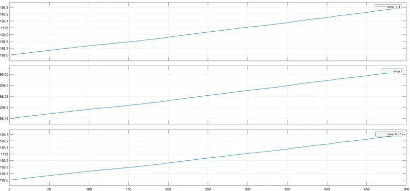
The above figure gives the various stages of temperature results temp of 1-4 cell and 5th cell and aslo 6-10 cells
Here the temperature results as been increased rapidly in the cell 1to4 ,5 and 6-10
So in cell 1 to 4 the temperature increases from 192 degrees to 194
In cell cell 5 the temperature increases from 298.5 to 299 degrees
In cell 6-10 the temperature increases from 192.6 to 193.2 degrees
So by comparing the above two graphs ime SoC and temperature we can observe that
There is a if the Soc decreases the temperature increases
The life cycle performance is so calle when in each round of full dicharge and then full charge of a battery then it is known as the life cycle
So mainly the battery life cycle can range from 500 to 1200
Which means the life cycle is 18 months to 3 years for a typical battery
conculsion:
we have complted the above task succesfully
For a 10 cell series lithium ion battery model we simulated the thermal effects and compared life cycle performance at various temperatures charge & discharge rates using MATLAB.