Project 2 Thermal modeling of battery pack
AIM:- To study Thermal modeling of the battery pack with the help of MATLAB and SIMULINK.
OBJECTIVES:-
1)For a 10 cell series lithium-ion battery model,simulate the thermal effects and compare life cycle performance at various temperatures,charge & discharge rates using MATLAB.
this will be based model which we are going to use for our project by doing some changes in it according to our requirements.
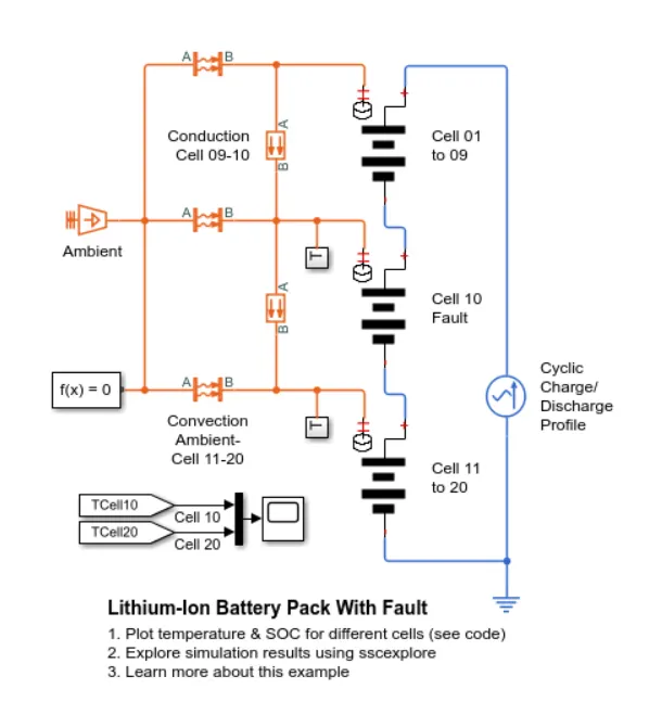
This example shows how to simulate a battery pack consisting of multiple series-connec ted cells eff iciently. It also shows how a fault can be introduced into one of the cells to see the impact on battery performance and cell temperatures. For eff iciency,identical series-connected cells are not just simply modeled by connecting cell models in series. Instead,a single cell is used,and the terminal voltage is scaled up by the number of cells. The fault is represented by changing the parameters for the Cell 10 Fault subsystem,reducing both capacity and open-circuit voltage,and increasing the resistance values.
-here we actually made changes in the base model according to our requirements to obtain results,
SIMULINK MODEL:-
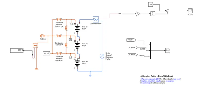
so for the 10-cell series lithium-ion battery here Iused Matlab and Simulink for findings thermal effect and life cycle performances related to temperature,charge,and discharge and also conduction and convection blocks are used to show how the heat transfer takes place in battery packs.
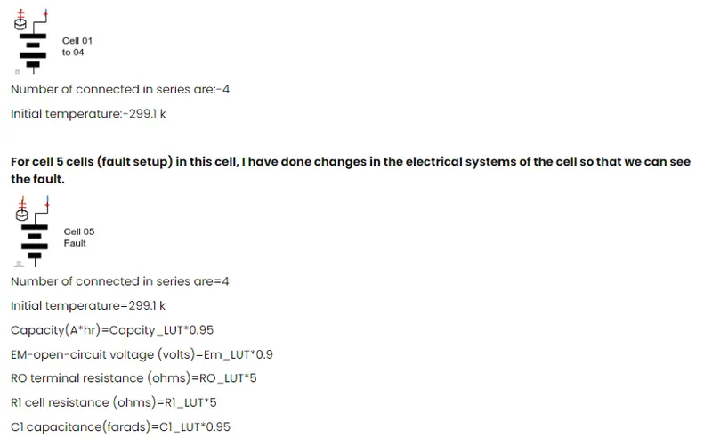
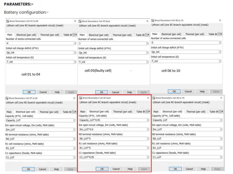
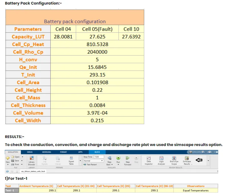
Lithium-ion battery pack with fault is to simulate a battery pack consists of multiple cells connected in series efficiently.it also shows how a fault can be introduced into one of the cells to the impact on battery performance and cell temperatures,for eff iciency the identicalseries-connec ted cells are not just simply model by connecting cell models in series. instead single cell is used,and the term inal voltage is scaled up by the number of cells.the fault is represented by changing the parameters for the cell 5 subsystem,reducing both the capacity and open-circuit voltage,and increasing the resistance values.
-How the connection is made
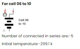
-10 lithium-ion battery cells are connected inwith the combination of three packs the flst consistent 4 cells in series 2nd pack consist of 1 cell which set to design as fault for study purpose to observe temperature changes within battery pack and the 3rd pack contain 5 cells inseries.
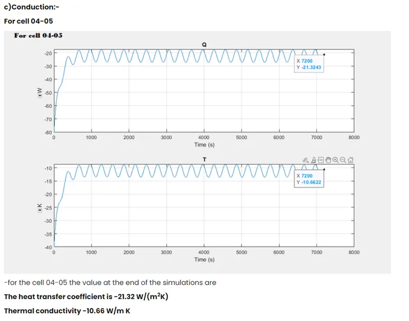
-the heat transfer is observed between the packs by conduction and convection block which are modes of heat transfer.
-T subsystem is attached in between every pack to plot the temperature graph of the cellof that particular battery pack.
-also external ambient temperature source is attached and also thermal sensor is attached to the same.to indicate the value in the display.
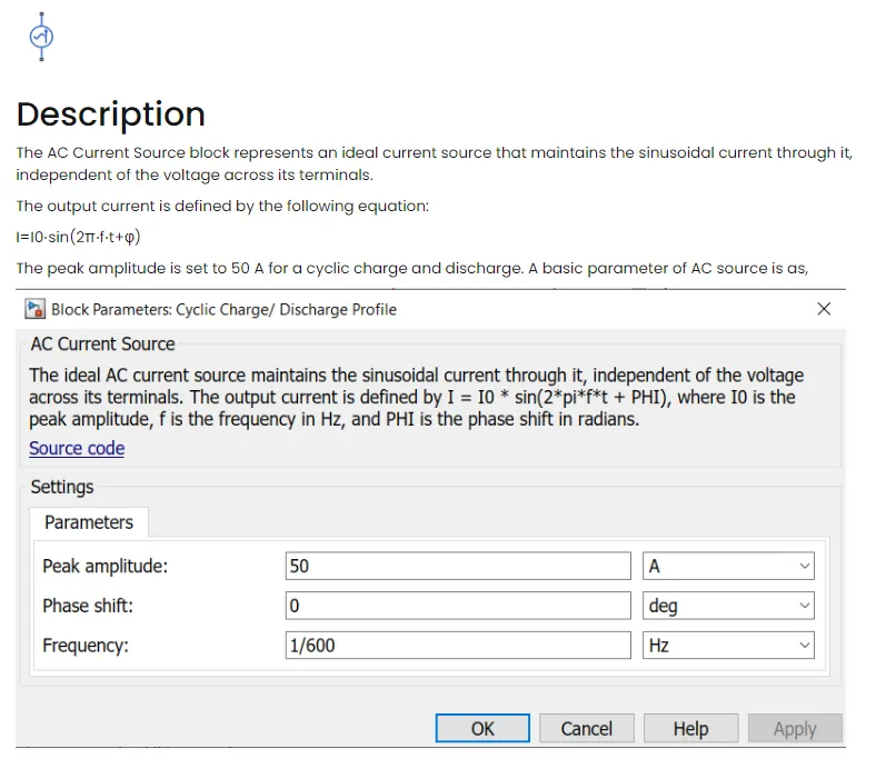
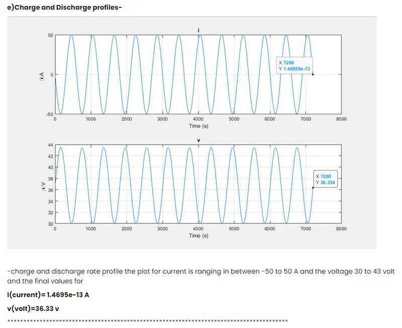
-this battery pack is connected to AC current source to observe the cyclic charge and discharge rate graph.
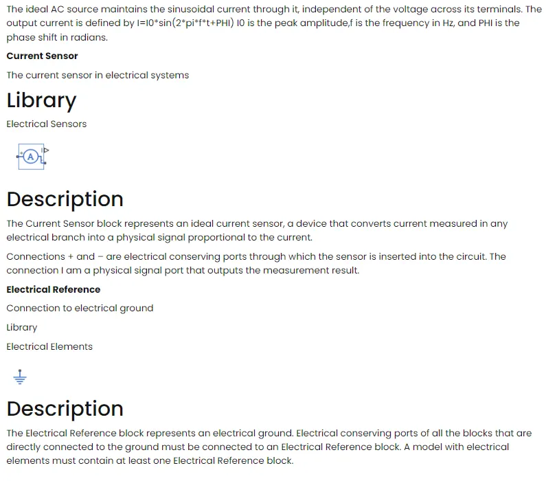
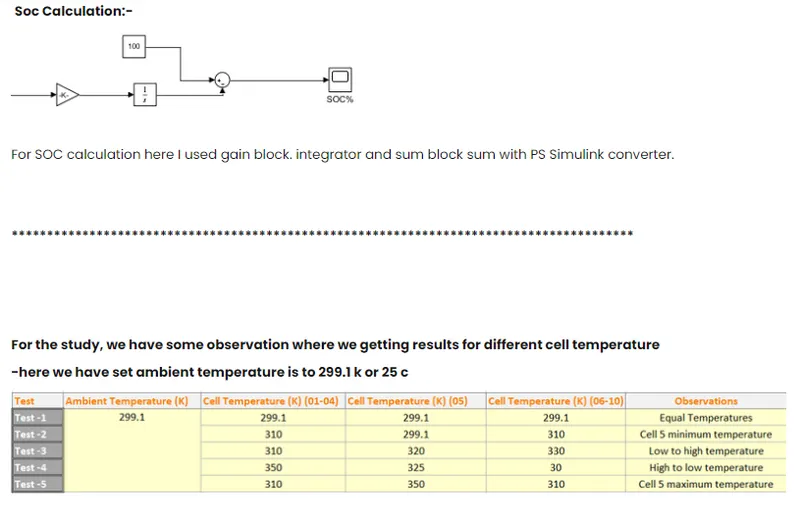
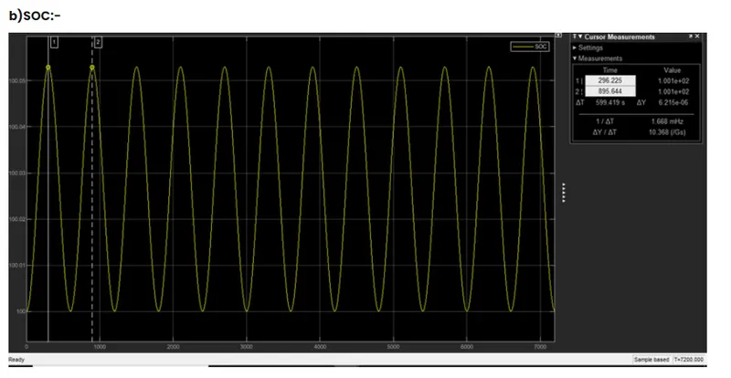
-also we added a current sensor in between the battery pack and AC current source to calculate the SOC of the battery
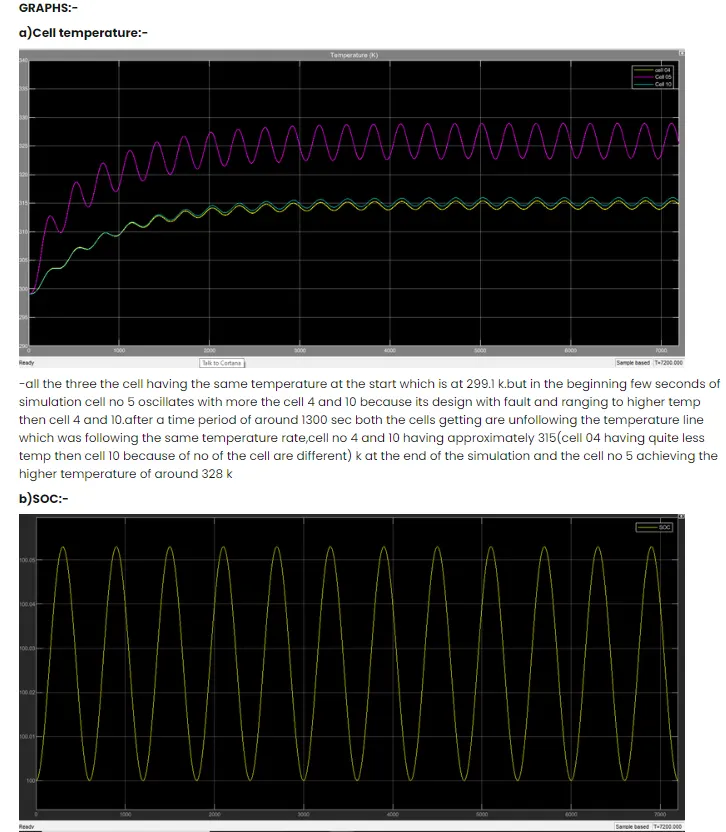
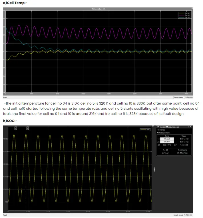
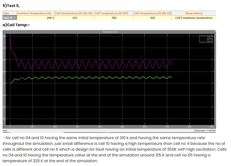
-the cell temperature and soc graphs are plotted in scope which indicating the temperature of cell no 4,cell no 5, and cell no 10
-all the other results are located in the simscape result menu.
Cell 01to 04 subsystem:-
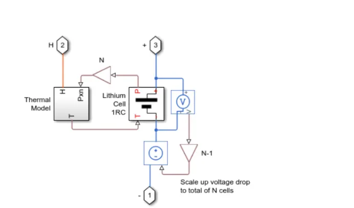
The cell subsystem basically consists of a thermal model and lithium cell lRC block which calculate the temperature and thermal effect for cells and overall calculate for the battery pack.
The block which are inside the cell subsystems are PS gain block which multiplies the input physical signals by a constant i.e y=u.*gain .another block are voltage sensor and current-voltage source.
The voltage sensor block represents an idealvoltage sensor;this is a device that converts voltage measured between any electric connection into a physical signal proportional to the voltage.
The current-voltage source represents an ideal voltage source that is powerf ul enough to maintain the specified voltage at its output regardless of the current passing through it. The outputvoltage is V=Vs,where Vs is the numeric va lue represents at the physicalsignal port.
Description
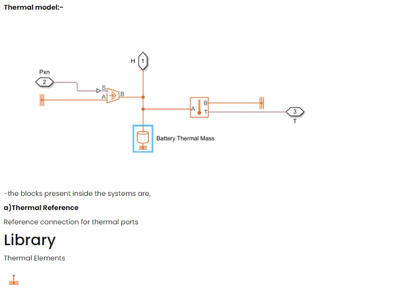
The Thermal Reference bloc k represents a thermalreference point,that is,a point with an absolute zero temperature, concerning which all the temperatures in the system are determined.
b)controlled Heat Flow Rate Source
Variable source of thermal energy,characterized by heat flow
expand all in page
library:
Simscape / Foundation Library / Thermal / Thermal Sources

Description
The Controlled Heat Flow Rate Source bloc k represents an ideal source of thermalenergy that is powerf ul enough to maintain spec if ied heat f low at its outlet regardless of the temperature difference across the source.
Connections A and B are thermal conserving ports corresponding to the source inlet and outlet,respectively. Port S is a physical signal port,through which the controlsignalthat drives the source is applied. You can use the entire
var iety of Simulink• signalsources to generate the desired heat f low variation profile.The heat f low throughthe source is directly proportionalto the signal at the controlport S.
The block positive direction is from port A to port B.This means that a positive signal at port s generates heat f low in
the direction from A to B.
3)ThermalMass
Mass in thermal systems
Library
Thermal Elements

Description
The Thermal Mass block represents a thermal mass,which reflects the ability of a material or a combination of materials to store internal energy.The property is characterized by the mass of the material and its specific heat. The thermal mass is described with the following equation:
Q=c·m*dT/dt
4)Temperature Sensor Ideal temperature sensor
Library
Thermal Sensors

Description
The Temperature Sensor block represents an ideal temperature sensor,a device that determines the temperature differential measured betweentwo points without drawing any heat.
Connections A and B are thermal conserving ports that connect to the two points where the temperature is being monitored. Port T is a physical signal port that outputs the temperature differentialva lue.
The block positive direction is from port A to port B. The measured temperature is determined as T = TA - Tg.
B)Lithium Cell lRC subsystem:-
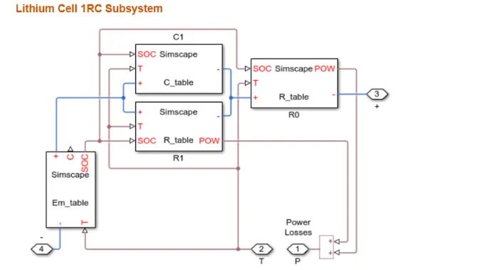
-this block espec ially cons ists of the capacitor (C)value table which depends upon an external physical signal input soc and T.it is assumed that the capacitor value is varying with the time and hence the equation i=c•ov/dt holds.
-Resistance va lue (R) table depend on externa l physical signal inputs SOC and T.
-Voltage va lue (EM) implements the cell's main branch voltage source and determines values for capacity(C) and state of charge (soc).
The defining the equations depends upon cell temperature T
THERMAL BEHAVIOUR AND FAULT SETUP:-
-Lithium-ion one cell one RC-Branch equivalent circuit detailfor 10 cells
For cell 01to 04
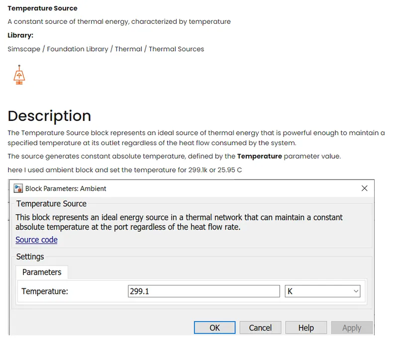
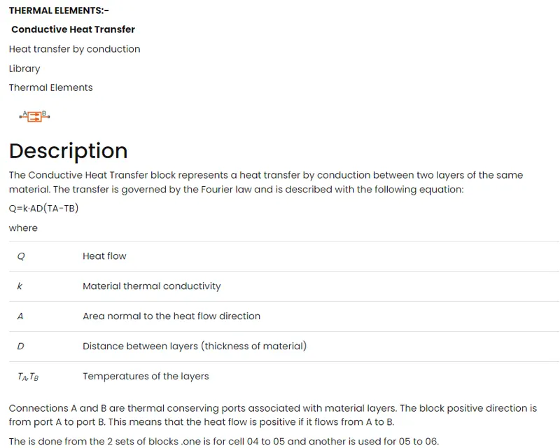
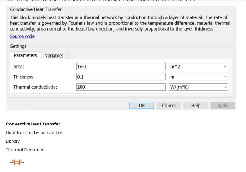
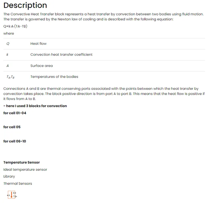
Description
The Temperature Sensor block represents an ideal temperature sensor,a device that determines the temperature differential measured betweentwo points without drawing any heat.
Connections A and B are thermal conserving ports that connect to the two points where the temperature is being monitored. Port T is a physical signal port that outputs the temperature differentialva lue.
The block positive direction is from port A to port B. The measured temperature is determined as T = TA - Tg.
Electrical Elements:-
here the output of one cell is connected with the SOC calculation whereas the output is connected to with AC source for the cyclic charge/discharge profile
a)AC Current Source
The ideal sinusoidal current source
Library
Electrical Sources
CONCLUSIONS :-
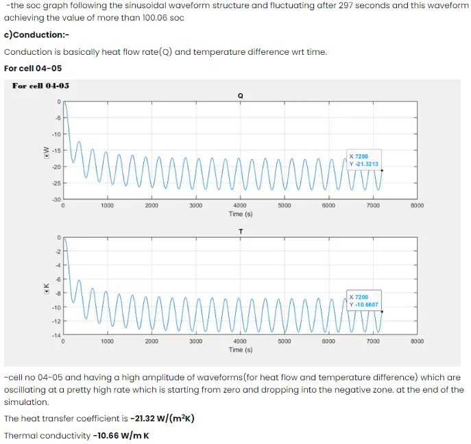
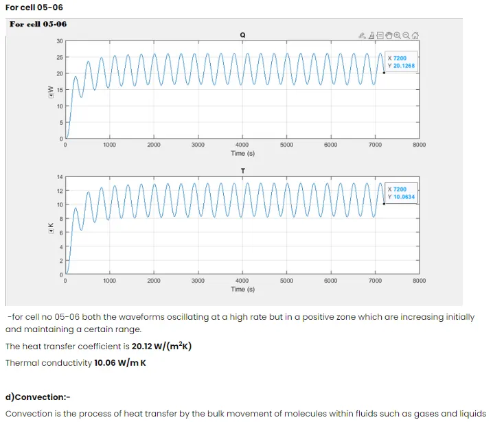
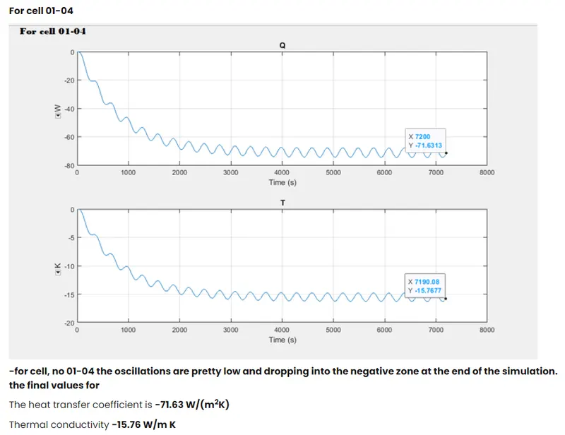
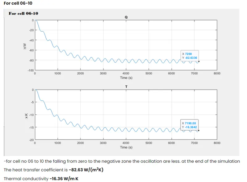
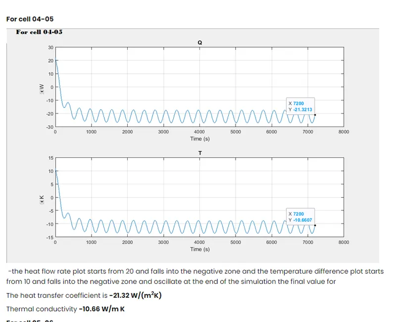
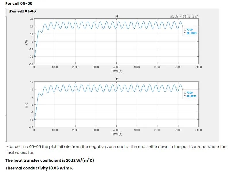
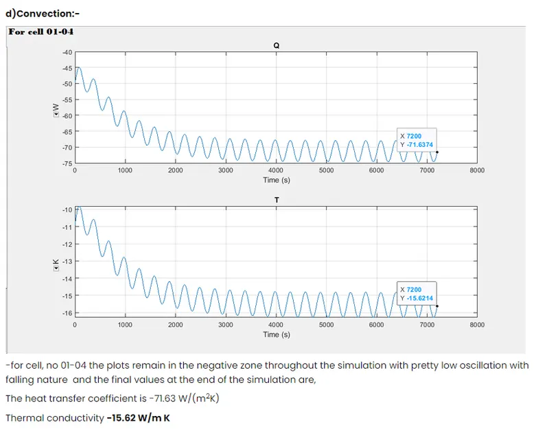
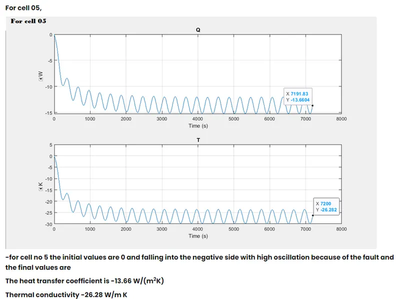
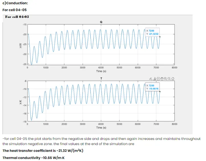
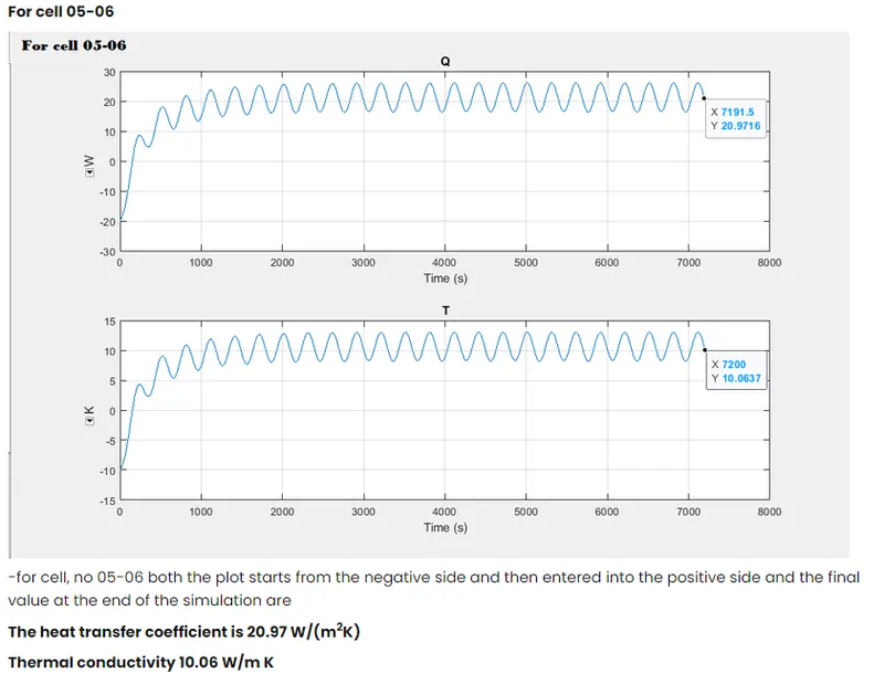
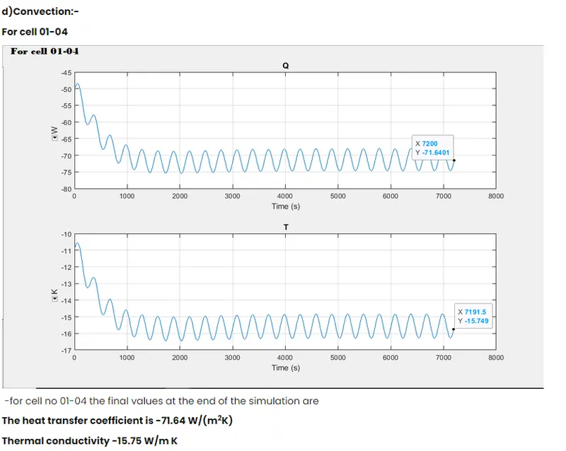
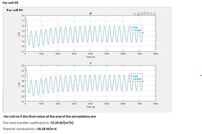
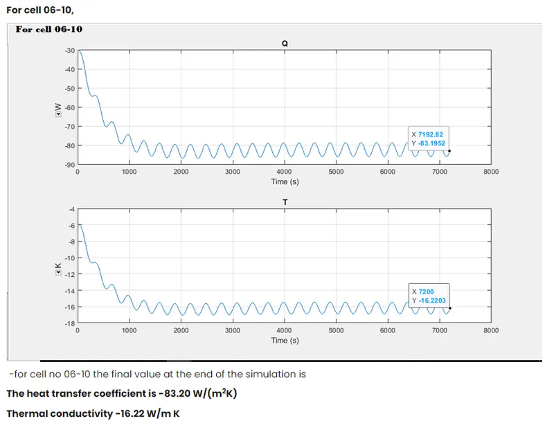
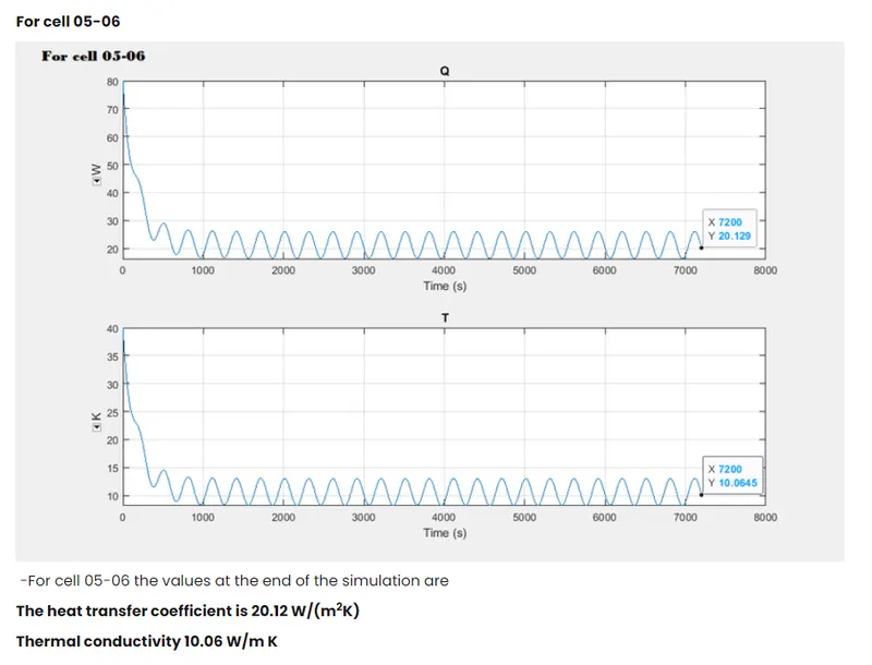
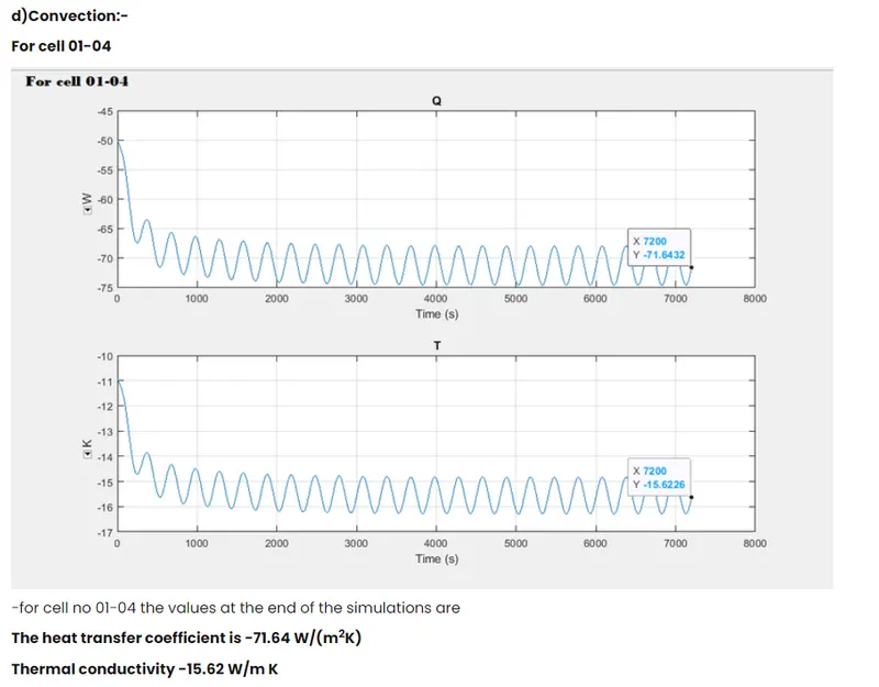
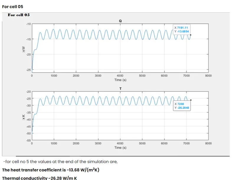
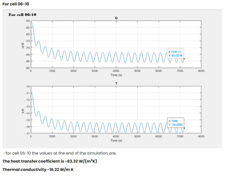
1)As the difference in temperature we can observe the changes in heat f low rate by conduction and convection.
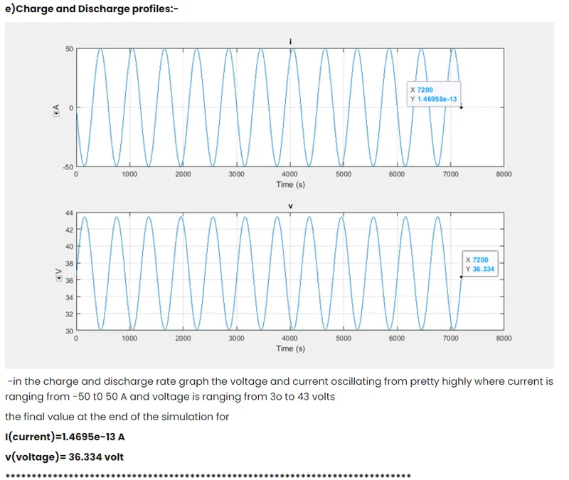
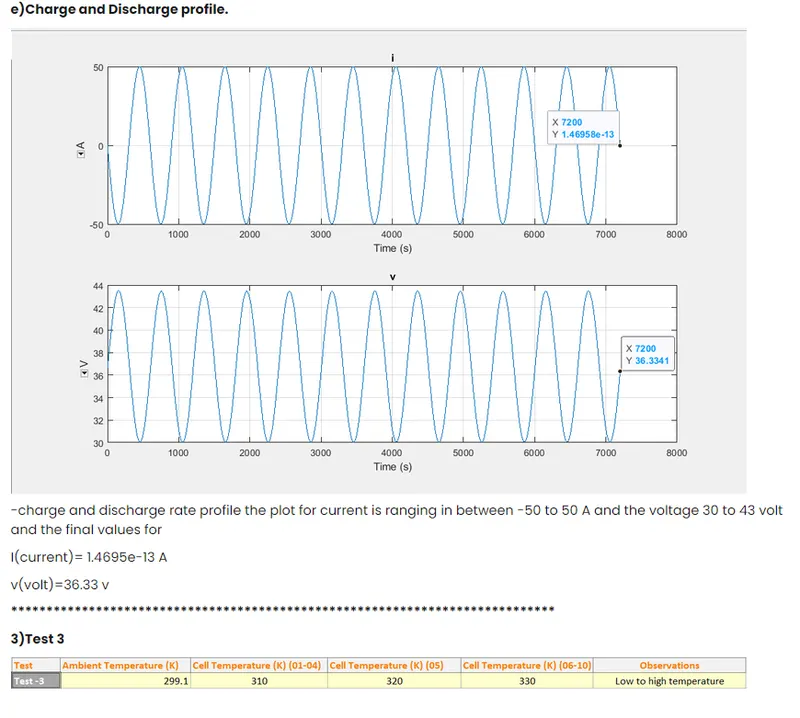
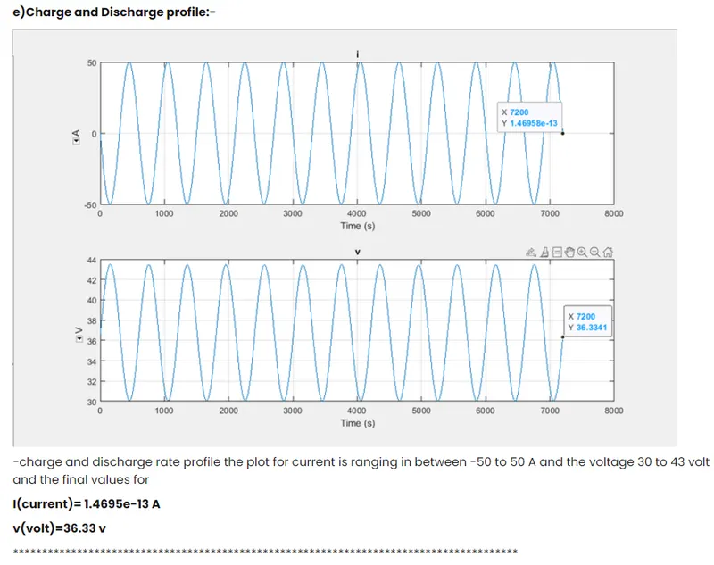
2)There are slight changes in cyclic charge and discharge as Ifixed peak amplitude at 50 A
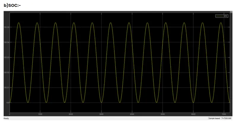
3)SOC for all the temperature remain the same so there is no difference in SOC graphs
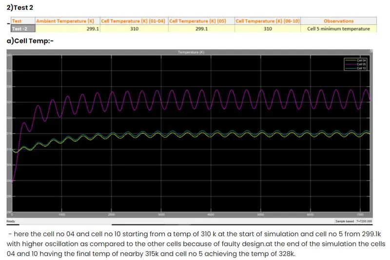
4) cell no 5 had higher oscillation and we can observe that in every graph because we design that cell for fault
REFERENCE:-
For base model:-https:/ /www.mathworks.com/ help/physmod/s imscape/ug/ lithium-ion- battery-pack with-fault.html