Project 2 - Speed Control of a Direct Current (DC) motor
Objective –
Using the Proportional, Integral, and Derivative (PID) control design to design, develop and test a controller to maintain a desired speed for the motor.
- Mathematical modelling from the first principles
- Modelling an Electrical Engineering system
- Simulink based modelling
- Control law design and test
- Stability of a dynamic system
Mathematical modelling from the first principles -
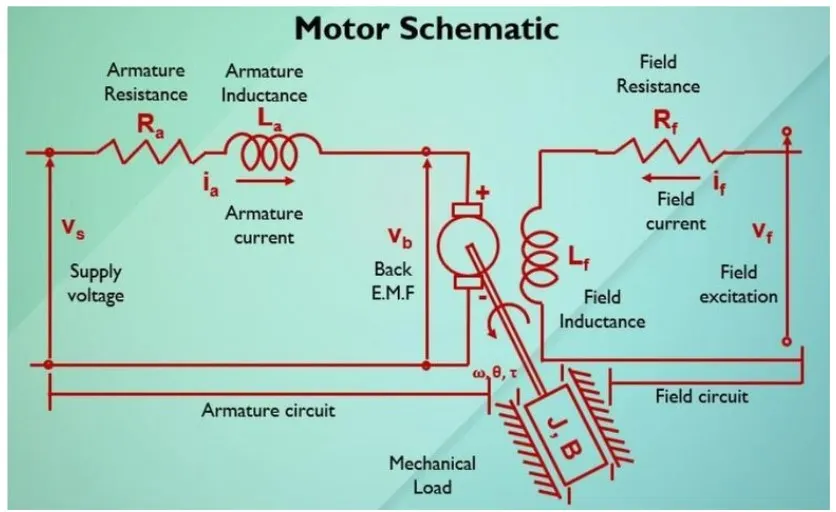
By using Kirchoff's voltage law, we can drive,
Vs = Ra ia + La dia/dt + Vb
For DC Motor modeling, Back EMF , Angular Velocity and Torque are related by,
Motor Torque T= Kt*I
Back EMF Vb= Km*w = Km* dtheta/dt
Where Km and Kt are the back EMF and Torque Constant respectively
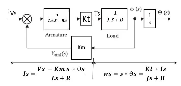
The open loop transfer function for the motor with speed(w) and supply voltage (Vs) can be derived as,
w(s)/v(s) = Kt / [ (La*S +Ra) (J*S+B) + Kt*Km]
By using this formula, we found how the DC motor is modeled mathematically with the ‘s’ domain and state space model equations.
Simulink based Modelling -
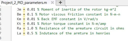
Using the MATLAB script following parameters are considered for DC Motor Sub system modeling
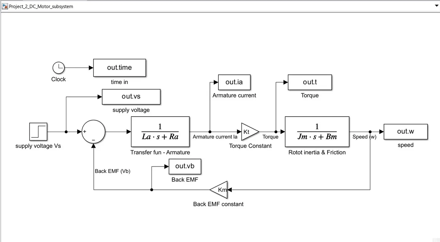
Simulink Model -
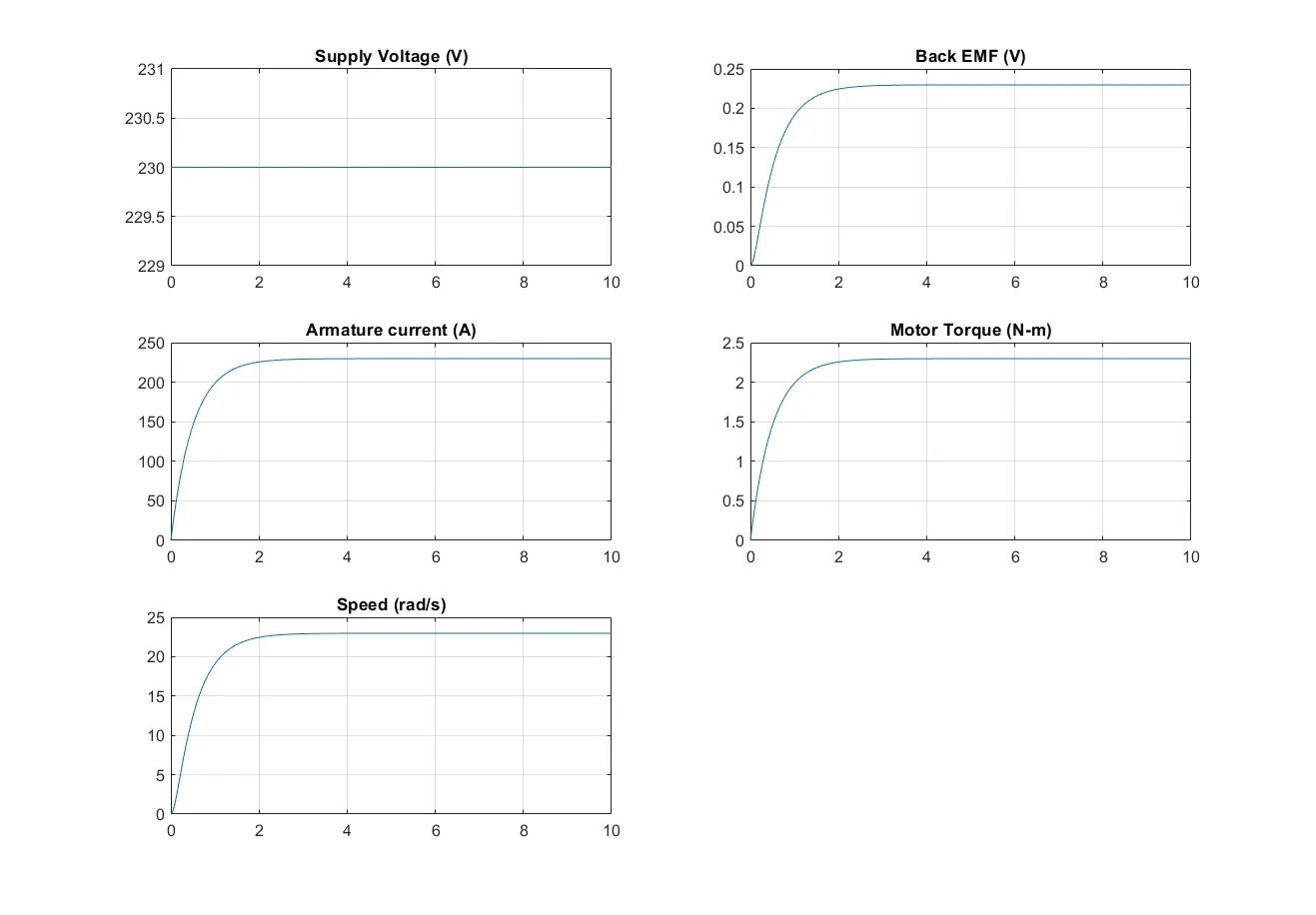
Output for DC motor Subsystem
 Control Law design and Testing of DC motor -
Using the Proportional, Integral, and Derivative (PID) control design, the Dc motor system design to test a controller to maintain a desired speed for the motor.
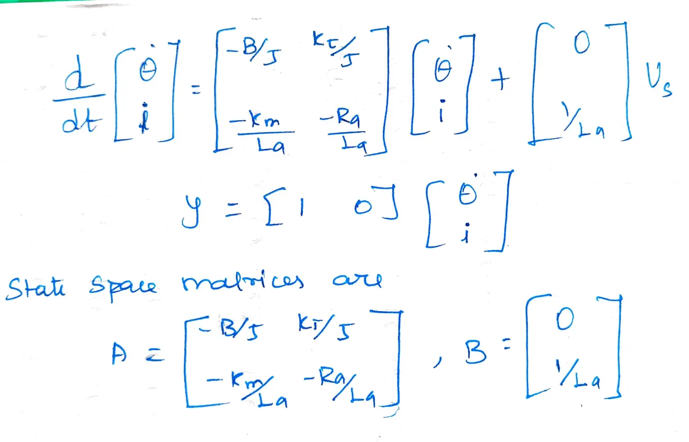
The State Space representation of Dc motor system is obtained using
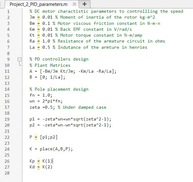
MATLAB Script for DC Motor control design
Using the MATLAB script following parameters are considered for DC Motor
From
the above script, we can determine the controller gain parameters Kp and Kd,
from the location of poles p1 and p2 using the ‘place’ command in MATLAB. The
Ki is tuned manually and Kp and Kd values are taken from the place command.
from the above parameters of DC Motor system, we got the below gains
Proportional Gain(kp) = 38.3133 and Derivative Gain(kd) = -2.8584
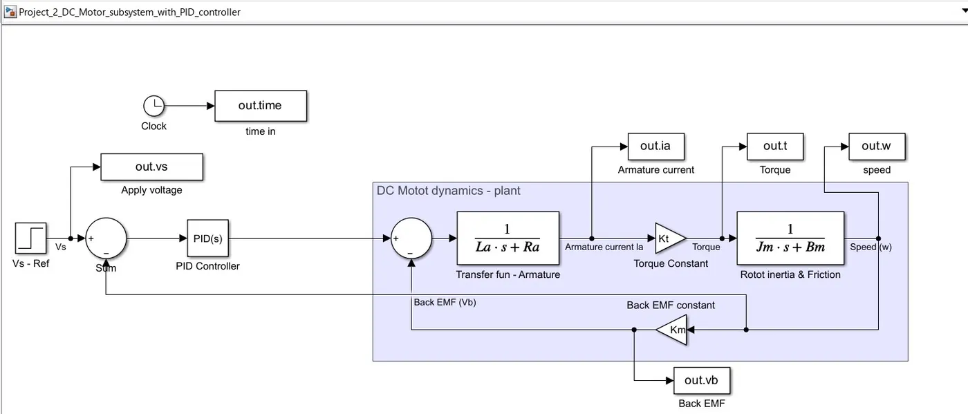
Simulink Model with PID control design
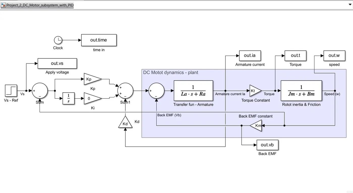
Output for DC motor System with PID Control - Kp and Kd as per Zeta = 0.5 and Ki = 0;
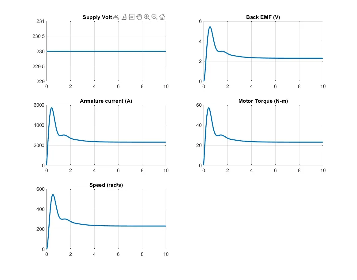
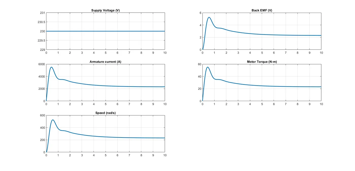
Output for DC motor System with PID Control - Kp, Kd as per Zeta = 0.5 (same as previous) and Ki = 10;
Simulink Model with PID Controller
By using the PID Controller block the DC Motor system is controlled with user input gains for proportional, Derivative and Integral
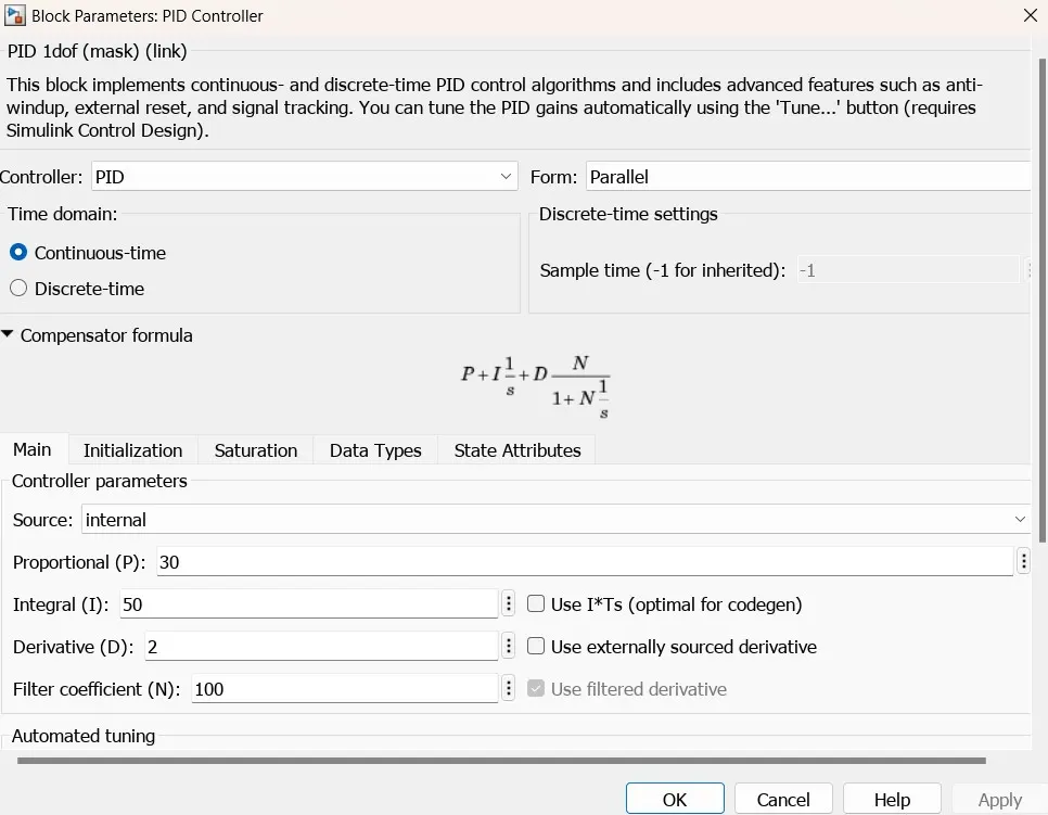
Simulink Model of PID Controller
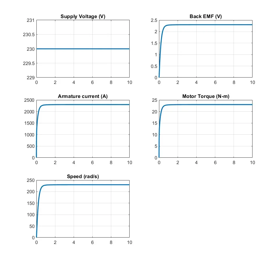
Output for the PID Controllers Vs = 230, Kp =30, Kd = 2 and Ki = 50
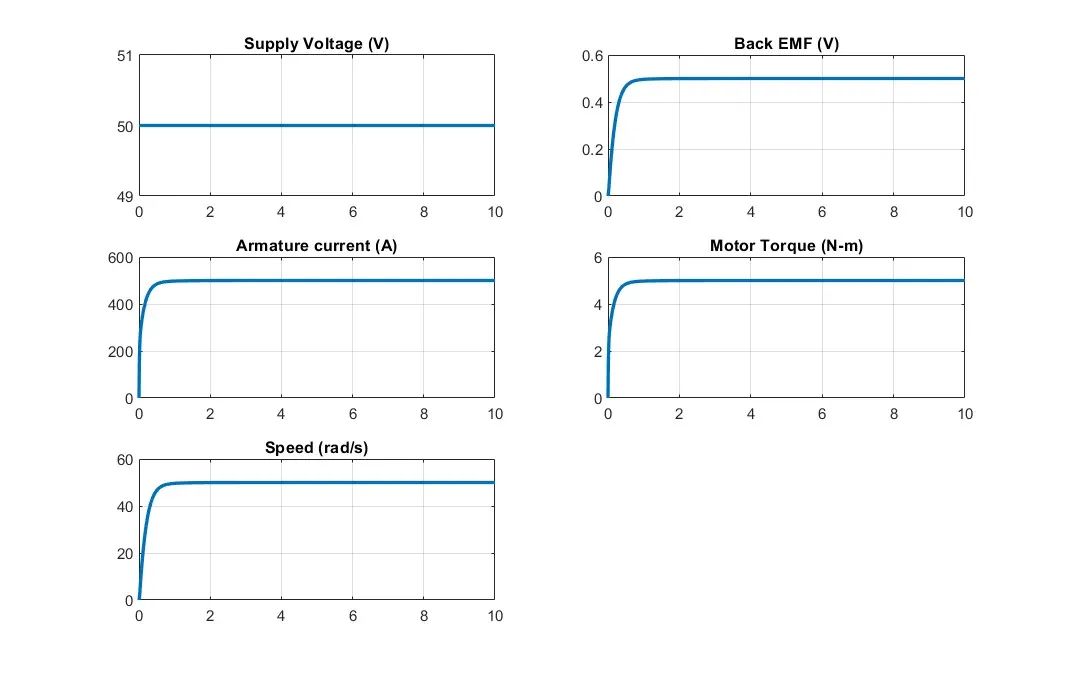
Output for the PID Controllers Vs =50, Kp =30, Kd = 2 and Ki = 50
The Stability of DC motor dynamics system -
The location of the poles decides the stability of the system. The Stability of the system is entirely dependent on the roots of the denominator polynomial in 'S' and it is having 2 roots.
The plane S can be represented as S = σ + J * W
where σ is the real part and W is the imaginary part representing the frequency
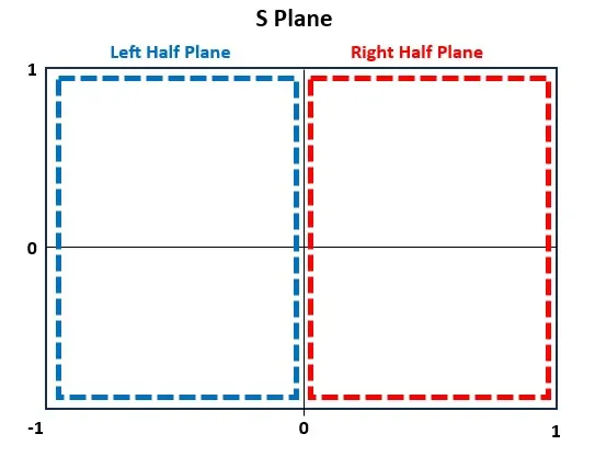
- If the roots lies in the left half of the S plane and on the j*w axis (i.e. σ = 0 Line). the dynamic system represents by the transfer function is stable
- If the roots lies in the right half of the plane, the dynamic system is unstable
Script for Pole Placement -
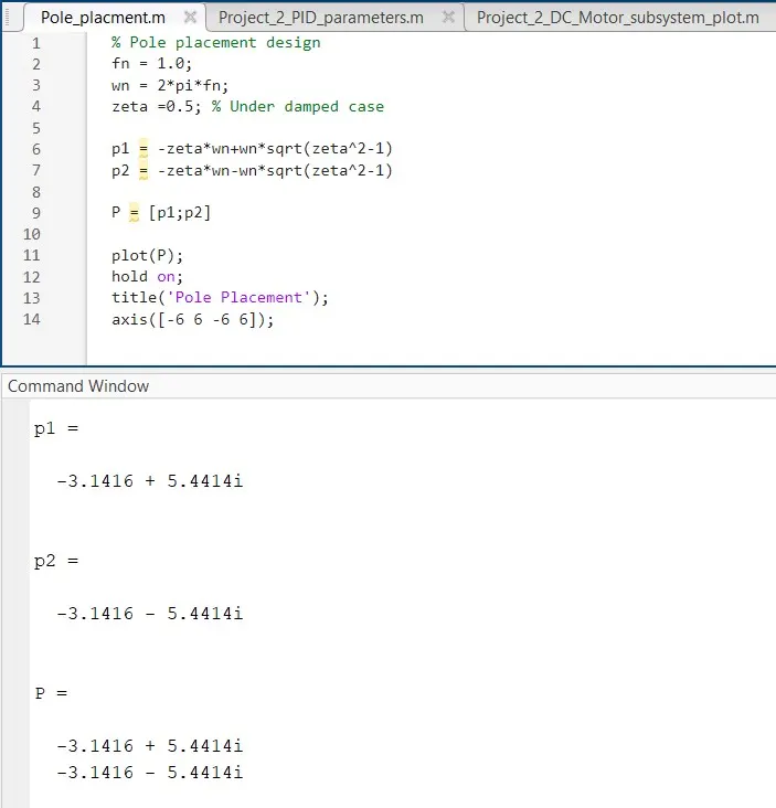
Pole Placement location in S plane -
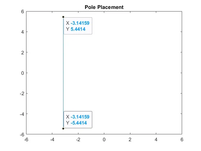
From the above plot, the poles are placed in the left plane of the S plane
Conclusion -
The DC motor subsystem is developed in Simulink as per the mathematical model. the speed of the motor is controlled using the PID control design and inbuilt PID controller bock for different gains. the stability of the system also checked with pole placement in the S plane.