Project 2 - Speed Control of a Direct Current (DC) motor
FOR dc motor we have to consider following parameters
�sign parameter of dc motor
Jm=0.01; % Inertia
Bm=0.1; % friction
Km=0.01; �ck emf
Kt=0.01; % torque
Ra=1; %resistance
La=0.5; %inductance
simulink model of dc motor
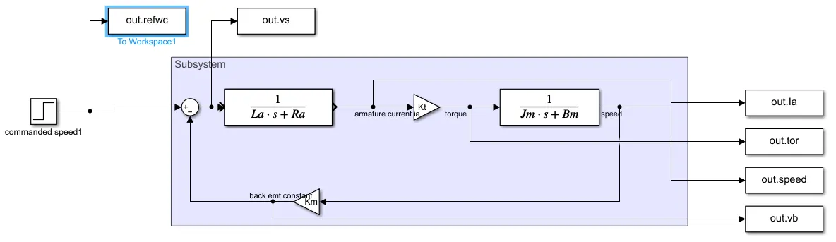
we given a supply volage of 230 v. the following graph is obtained
%plotting the graphs of dc motor
figure(2);
subplot(321);plot(out.time,out.vs);grid;title('supply voltage');
subplot(322);plot(out.time,out.vb);grid;title('back emf');
subplot(323);plot(out.time,out.Ia);grid;title('armature current');
subplot(324);plot(out.time,out.tor);grid;title('torque');
subplot(325);plot(out.time,out.speed);grid;title('speed');
subplot(326);plot(out.time,out.refwc);grid;title('reference speed');
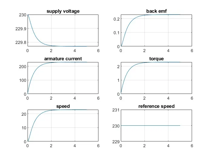
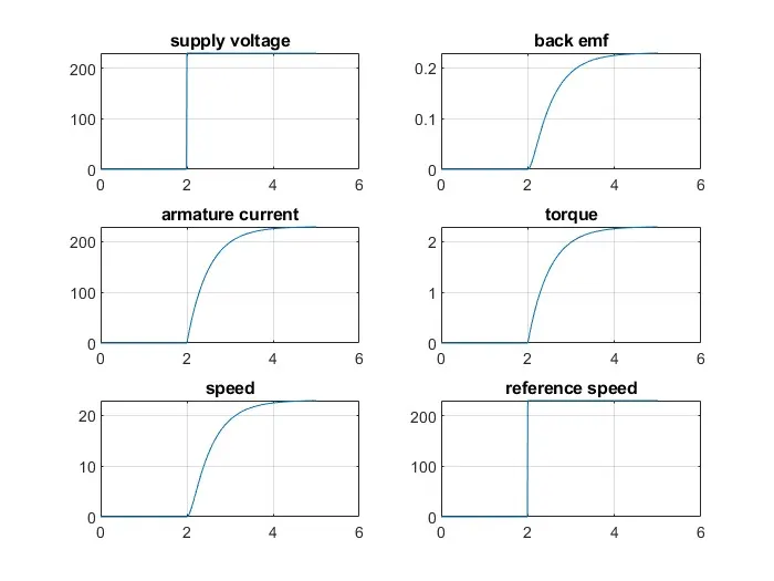
we given a step time 2sec the following graph obtained
Design of DC MOTOR with PID controller
%PID design
A=[-Bm/Jm Kt/Jm; -Km/La -Ra/La];
B=[0 ; 1/La];
fn=1;
wn=2*pi*fn;
zeta=0.5;
p1=-zeta*wn+wn*sqrt(zeta^2-1);
p2=-zeta*wn-wn*sqrt(zeta^2-1);
P=[p1;p2];
K=place(A,B,P);
kp=K(1);
kd=K(2);
ki=.4;
we initilizing fn,zeta, then calculating the poles . using place command we are finding k value . kp=k1 & kd=K2,
here ki=0
simulink model
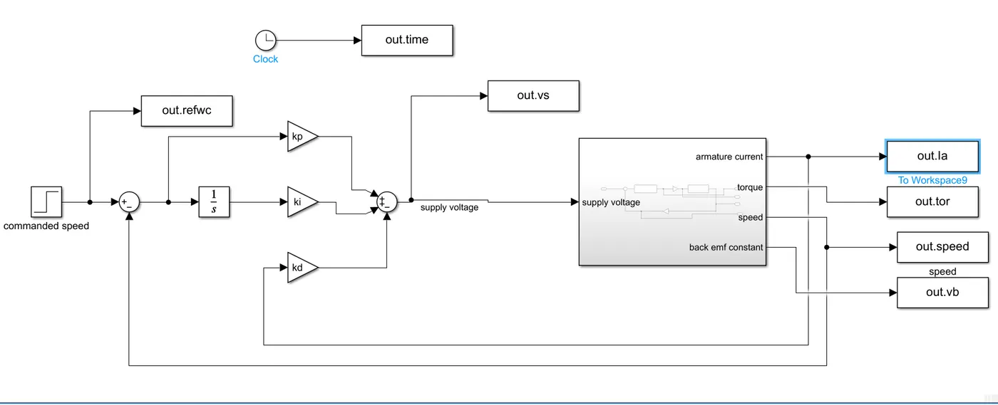
we created dc motor system as sub system
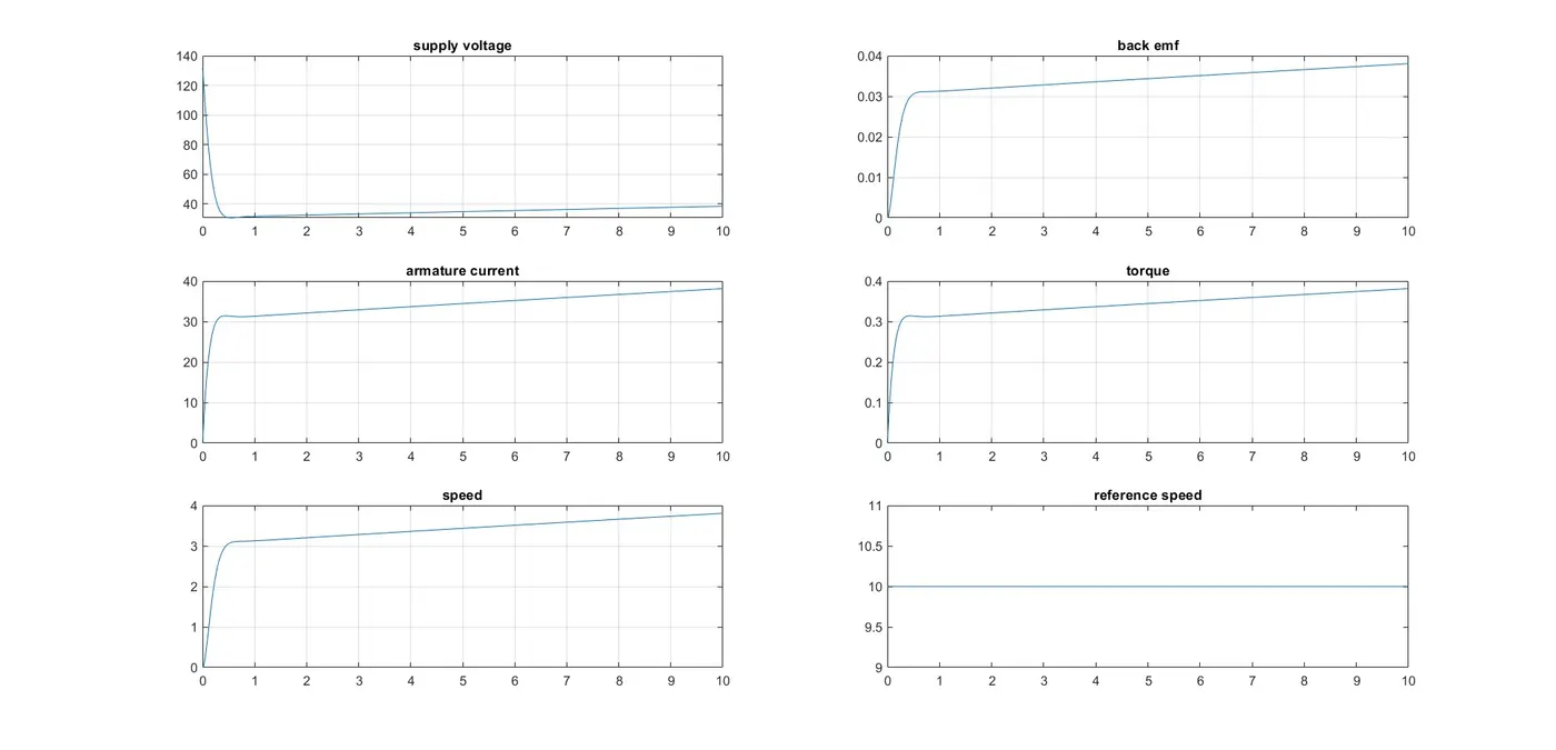
case 1
plot graph when kp=13.1805 ,kd=2, ki= .5
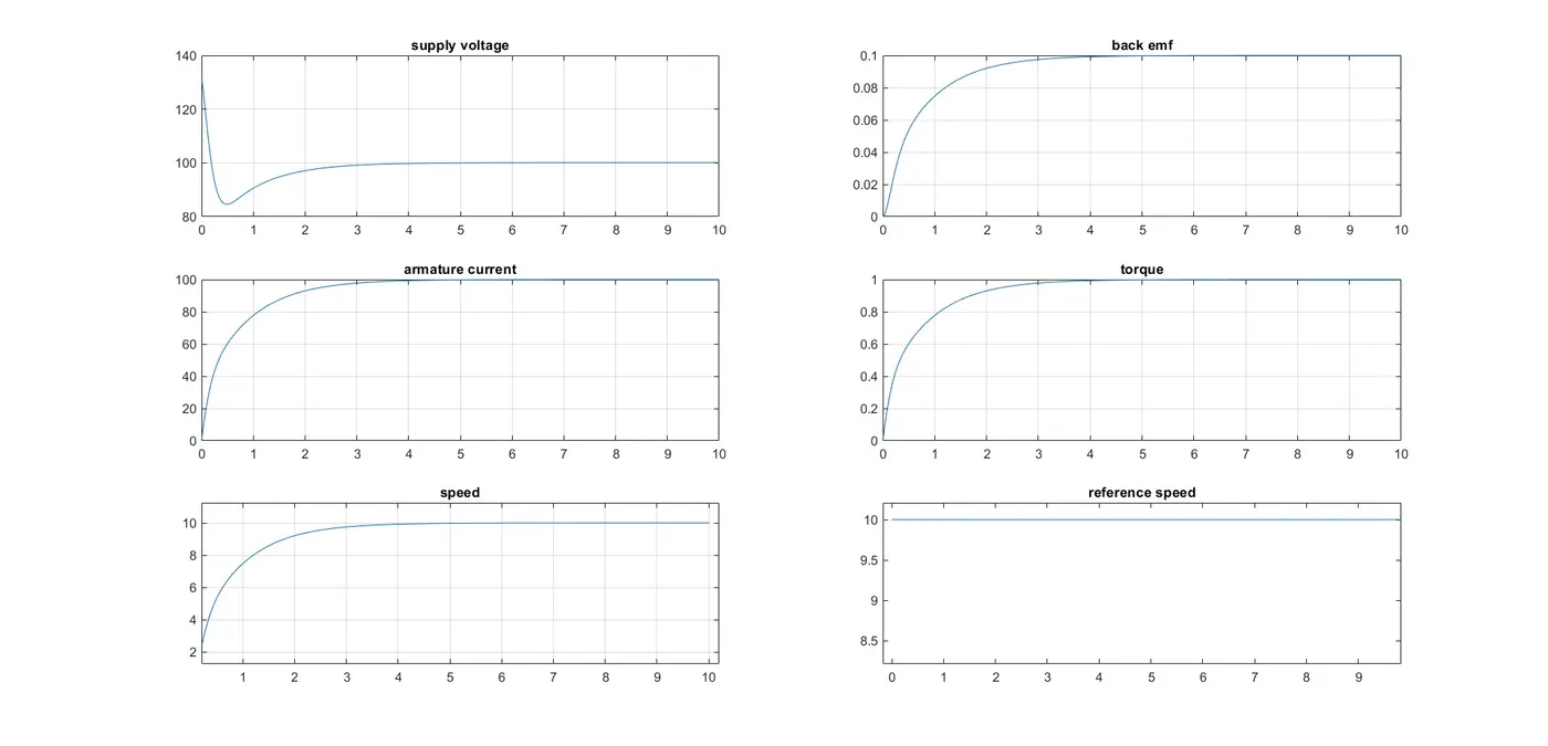
cas 2
plot graph when kp=13.1805 ,kd=2, ki= 40
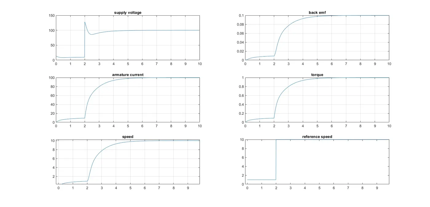
case 3 reference signal step time 2 sec initial value 1
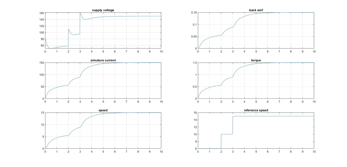
case 4
conclusion
we have desihned the dc motor and dc motor with pid controller. case 2 with ki=40 speed 10, output speed is same matching with the reference speed. both plot are maintain same .so we can say this the desired speed of dc motor.
case 3 & case 4 we have tried step signal as reference speed . here also the plot maintain the same .case 4 we add two step signal and the result given as reference speed.