Project 2 - Speed Control of a Direct Current (DC) motor
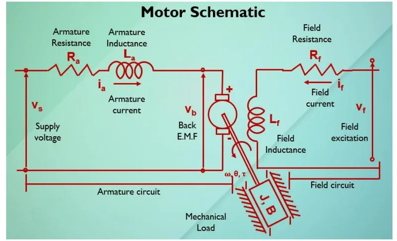
In this project, a Simulink model for the DC motor will be first developed per the schematic shown in Figure 1.
Use the Proportional, Integral, and Derivative (PID) control design knowledge gained in the training to design, develop and test a controller to maintain a desired speed for the motor.
Key Highlights:
- Mathematical modeling from the first principles
- Modeling an Electrical Engineering system
- Simulink based modeling
- Control law design and test
- Stability of a dynamic system
Deliverables:
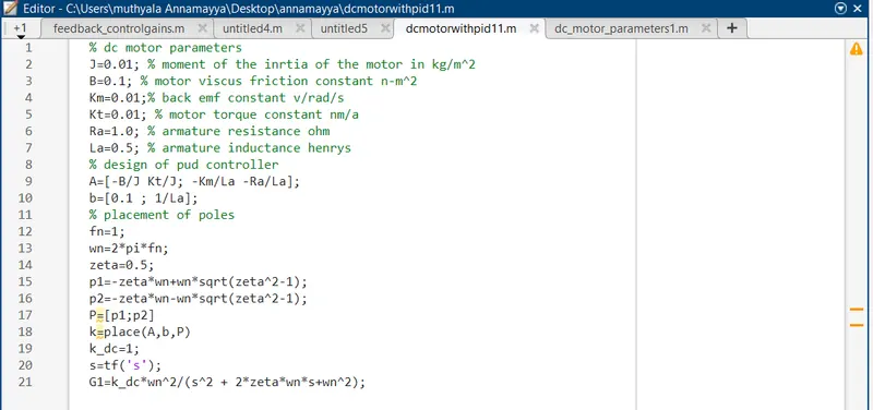
- Matlab script to define modeling and control design parameters
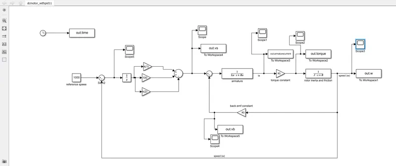
- Simulink model to simulate and verify the design.
ans:
A DC motor, short for Direct Current motor, is an electrical machine that converts electrical energy into mechanical energy through the interaction of magnetic fields. It operates using direct current, where the flow of electric current is unidirectional.
Here are some key aspects of DC motors:
-
Basic Operation: A DC motor consists of two main parts: the stator (stationary part) and the rotor (rotating part). The stator typically contains field windings that create a magnetic field when current flows through them. The rotor, usually equipped with coils, experiences a force due to the interaction between the magnetic fields of the stator and rotor. This force causes the rotor to rotate.
-
Brushes and Commutator: Many traditional DC motors use brushes and a commutator to switch the direction of the current in the rotor coils as the rotor turns. The commutator is a rotary switch that reverses the current direction in the rotor coils, ensuring that the magnetic forces always push the rotor in the same direction of rotation.
-
Types of DC Motors:
- Series Motor: In this type, the field winding and the armature winding (rotor winding) are connected in series. Series motors are known for high starting torque, making them suitable for applications like electric locomotives and heavy machinery.
- Shunt Motor: Here, the field winding and armature winding are connected in parallel. Shunt motors offer relatively constant speed characteristics and are commonly used in industrial applications.
- Compound Motor: Compound motors combine series and shunt characteristics, offering a blend of both high starting torque and relatively constant speed.
- Permanent Magnet DC Motor: Instead of using field windings, these motors have permanent magnets in the stator to produce a magnetic field. They are often smaller, more efficient, and require less maintenance than brushed DC motors.
-
Advantages:
- Simple construction and control.
- High starting torque, especially in series motors.
- Speed can be easily controlled by varying the voltage applied.
-
Disadvantages:
- Brushes and commutators can wear out over time, requiring maintenance.
- Limited lifespan due to wear and tear.
- Brush friction can lead to inefficiency and sparking.
-
Applications:
- DC motors are used in various applications, such as electric vehicles, robotics, conveyor systems, industrial machinery, fans, pumps, and appliances like hairdryers and power tools.
-
Modern Developments: In recent years, there has been a shift towards brushless DC (BLDC) motors, which use electronic controllers to energize the stator windings in a specific sequence. BLDC motors offer advantages like higher efficiency, longer lifespan, and reduced maintenance compared to traditional brushed DC motors.
Overall, DC motors have played a crucial role in many industries and applications due to their simplicity, controllability, and ability to provide reliable mechanical power