Project - Position control of mass spring damper system
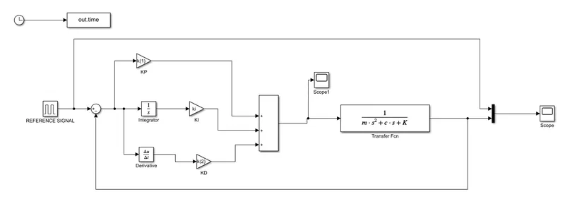
1.Obtain the transfer function of a mass spring damper system and use it in the model. Add a PID controller to adjust the force on mass so that its position follows a reference signal.
Take m = 3.6; %kg k = 400; %N/m c = 100; %Ns/m
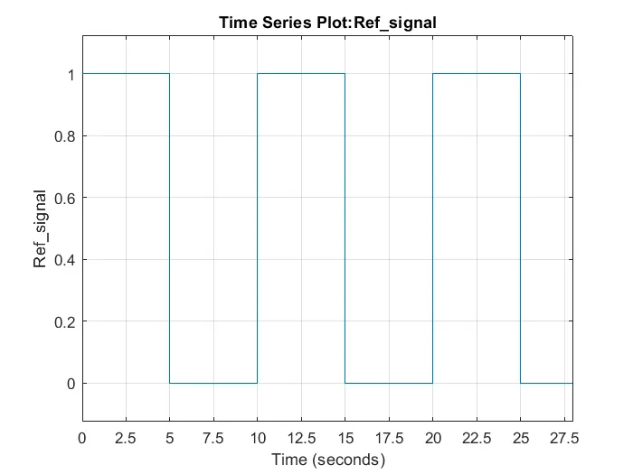
The reference signal is shown in the following figure.
ANS:
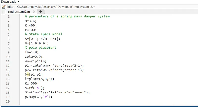
the code of the simulink model
the simulink model of the code
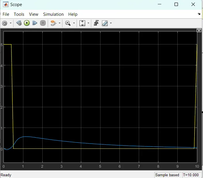
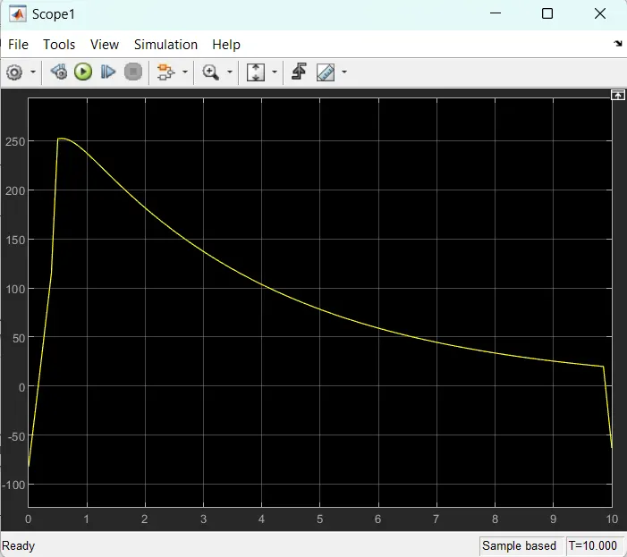
the out put of the above two scopes
we are using a in simulink model some blocks .which are
scope,gain, pulse generator,integrator,sum,mux,transfer function.
about these blocks is
1.scope: The Scope block displays each bus element signal, in the order the elements appear in the bus, from the top to the bottom. Nested bus elements are flattened. For example, in this model the nestedBus signal has the const, subSignal, and step signals as elements. The subSignal sub-bus has the chirp and sine signals as its bus elements.
2.gain block: Simulink Math Operations and Fixed-Point Blockset Math. Description. The Gain block multiplies the input by a constant value (gain). The input and the gain can each be a scalar, vector, or matrix. You specify the value of the gain in the Gain parameter.
3. pulse generator: The Pulse Generator block generates square wave pulses at regular intervals. The block's waveform parameters, Amplitude, Pulse Width, Period, and Phase Delay, determine the shape of the output waveform. The following diagram shows how each parameter affects the waveform.
4.integrator block:The Integrator block outputs the value of the integral of its input signal with respect to time.
5.sum block: The Sum block performs addition or subtraction on its inputs. The Add, Subtract, Sum of Elements, and Sum blocks are identical blocks. This block can add or subtract scalar, vector, or matrix inputs. It can also collapse the elements of a signal and perform a summation.
6.mux: The Mux block combines its inputs into a single output. An input can be a scalar, vector, or matrix signal. Depending on its inputs, the output of a Mux block is a vector or a composite signal, i.e., a signal containing both matrix and vector elements.
7.transfer functin:
-
A transfer function is a convenient way to represent a linear, time-invariant system in terms of its input-output relationship. It is obtained by applying a Laplace transform to the differential equations describing system dynamics, assuming zero initial conditions.