Project 2 - Rankine cycle Simulator
AIM : To create a Rankine Cycle Simulator using MATLAB.
THEORY :-
The Rankine cycle is an idealized thermodynamic cycle describing the process by which certain heat engines, such as steam turbines or reciprocating steam engines, allow mechanical work to be extracted from a fluid as it moves between a heat source and heat sink. The Rankine cycle is named after William John Macquorn Rankine, a Scottish polymath professor at Glasgow University.
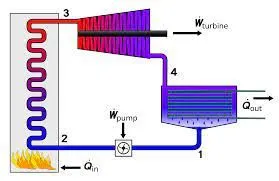
The ideal Rankine cycle does not involve any internal irreversibilities and consists of the following four processes:
1-2 Isentropic compression in a pump
2-3 Constant-pressure heat addition in a boiler
3-4 Isentropic expansion in a turbine
4-1 Constant-pressure heat rejection in a condenser
Required Inputs :
Turbine Inlet temperature = 400° C
Turbine Inlet Pressure = 30 bars
Turbine Outlet Pressure = 0.05 bars = Condenser Inlet Pressure
MAIN PROGRAM CODE :
1. Initially, the different process in a rankine cycle is displayed.
2. The input parameters are obtained from the user.
3. The different parameters at the turbine inlet condition is derived. The various constant values are obtained from the steam table.
4. Here XSteam library is used for obtaining the steam table values.
5. Then, the different parameters at turbine outlet condition is derived.
6. In condenser outlet condition, different parameters are derived with the help of XSteam library.
7. The various values at the pump outlet condition are also calculated.
8. Once the different values at different conditions are obtained, we can proceed further for calculating the main resultant values.
9. The work done, input and output heat and the efficiency of the rankine cycle is calculated.
10. The back work ratio is also calculated.
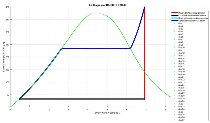
11. From all the values obtained, the h-s plot and the t-s plot were drawn
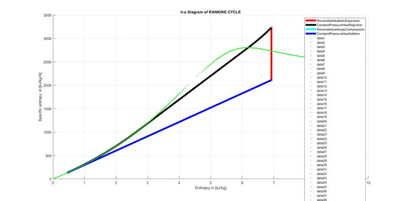
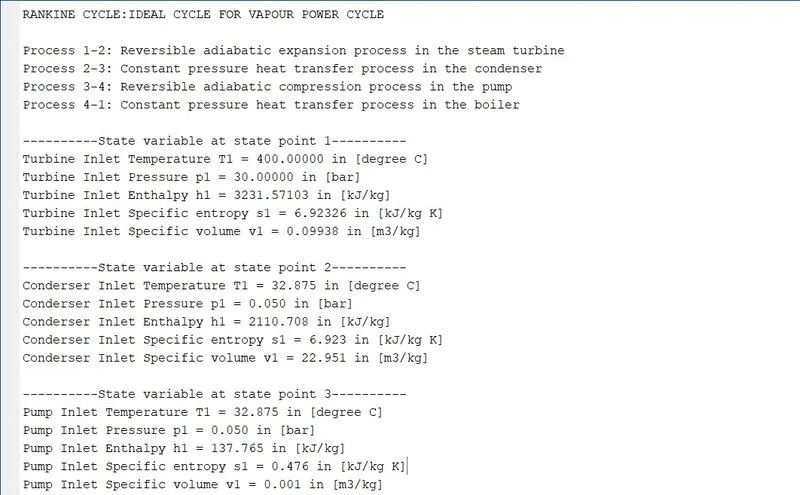
12. All the values calculated are shown under command window result.
HS -
COMMAND WINDOW OUTPUT :
RANKINE CYCLE:IDEAL CYCLE FOR VAPOUR POWER CYCLE
Process 1-2: Reversible adiabatic expansion process in the steam turbine
Process 2-3: Constant pressure heat transfer process in the condenser
Process 3-4: Reversible adiabatic compression process in the pump
Process 4-1: Constant pressure heat transfer process in the boiler
----------State variable at state point 1----------
Turbine Inlet Temperature T1 = 400.00000 in [degree C]
Turbine Inlet Pressure p1 = 30.00000 in [bar]
Turbine Inlet Enthalpy h1 = 3231.57103 in [kJ/kg]
Turbine Inlet Specific entropy s1 = 6.92326 in [kJ/kg K]
Turbine Inlet Specific volume v1 = 0.09938 in [m3/kg]
----------State variable at state point 2----------
Conderser Inlet Temperature T1 = 32.875 in [degree C]
Conderser Inlet Pressure p1 = 0.050 in [bar]
Conderser Inlet Enthalpy h1 = 2110.708 in [kJ/kg]
Conderser Inlet Specific entropy s1 = 6.923 in [kJ/kg K]
Conderser Inlet Specific volume v1 = 22.951 in [m3/kg]
----------State variable at state point 3----------
Pump Inlet Temperature T1 = 32.875 in [degree C]
Pump Inlet Pressure p1 = 0.050 in [bar]
Pump Inlet Enthalpy h1 = 137.765 in [kJ/kg]
Pump Inlet Specific entropy s1 = 0.476 in [kJ/kg K]
Pump Inlet Specific volume v1 = 0.001 in [m3/kg]
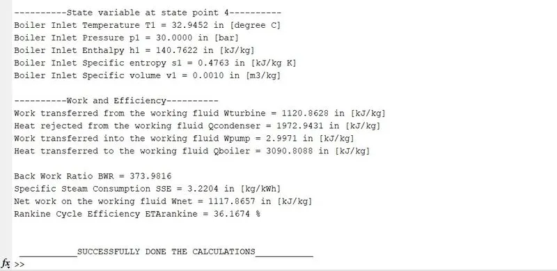
----------State variable at state point 4----------
Boiler Inlet Temperature T1 = 32.9452 in [degree C]
Boiler Inlet Pressure p1 = 30.0000 in [bar]
Boiler Inlet Enthalpy h1 = 140.7622 in [kJ/kg]
Boiler Inlet Specific entropy s1 = 0.4763 in [kJ/kg K]
Boiler Inlet Specific volume v1 = 0.0010 in [m3/kg]
----------Work and Efficiency----------
Work transferred from the working fluid Wturbine = 1120.8628 in [kJ/kg]
Heat rejected from the working fluid Qcondenser = 1972.9431 in [kJ/kg]
Work transferred into the working fluid Wpump = 2.9971 in [kJ/kg]
Heat transferred to the working fluid Qboiler = 3090.8088 in [kJ/kg]
Back Work Ratio BWR = 373.9816
Specific Steam Consumption SSE = 3.2204 in [kg/kWh]
Net work on the working fluid Wnet = 1117.8657 in [kJ/kg]
Rankine Cycle Efficiency ETArankine = 36.1674 %
___________SUCCESSFULLY DONE THE CALCULATIONS___________
SCREENSHOTS :
REFERENCE :
1. GOOGLE.COM
2. SKILLLYNC.COM
CONCLUSION :
Thus the rankine cycle simulator was made using MATLAB. The result values for the input parameters and the plots are shown.
ERRORS FACED AND SOLUTION :
1. BASIC SPELLING MISTAKES SOLVED OVER THOROUGHING THE PROGRAM CODE.
2. FORGOT TO PUT THE STEAMX FILE IN CODE FOLDER SO GETTING ERROR SOLVED BY PLACING THE FILE IN THE SAME CODE FOLDER.
3. BASIC MISTAKES IN BRACKET PUTTING AND INVERTED COMMAS SOLVED BY PUTTING IT.