Project 2 - Rankine cycle Simulator
AIM: -  To create Rankine Cycle Simulator
THEORY: -
The Rankine cycle consists of following 4 processes
1-2 refers to Isentropic Expansion in the Turbine
2-3 refers to Constant pressure heat rejection by the condenser
3-4 refers to Isentropic Compression in the pump
4-1 refers to Constant Pressure heat addition by the boiler

Following are the inputs provided for the calculation
%p1=pressure at point 1 or turbine inlet in bar
p1=30
%t1=temperature at point 1 or turbine inlet in degrees Celsius
T1=400
%H1=enthalpy at point 1(from steam tables) in KJ/kg considering pressure & temperature
H1= 3231.57
%Entropy at point 1(from steam tables) in KJ/kgK considering pressure & temperature
S1= 6.92
Similarly the values of enthalpy & entropy are calculated at point 2 by using the dryness fraction formulae as the outlet state of the fluid is Gas + vapour after turbine.

Dryness fraction details
In case of pure substances like water, if it is single phase like vapour or liquid, we need 2 independent properties for determining the 3rd property or for determining any other thermodynamic property like entropy, enthalpy etc.
But if it exists in 2 phases, we require additional information also known as Quality or dryness fraction (x). For example, let us take a sample of 2 phase mixture,
M(mass of the sample)= Mf (mass of liquid)+Mg (mass of vapour)

X= Mass of vapour / Mass of sample = Mf /M or Mf /Mf + Mg
At saturated vapour line x =0
At saturated vapour line x =1

so At state point 2
s2=s1 (as the process of expansion is sentropic in tubine)
h2 & s2 are calucated using dryness fraction

At state point 3
p3 = p2; (since the process is isobaric)
T3 = T2;(as only heat is lost by vapour phase of water to become liquid phase)
s3 = sf2;(since the fluid is completely liquid at this stage so we take the liquid enthalpy from steam tables)
h3 = hf2;(since the fluid is completely liquid at this stage so we take the liquid enthalpy from steam tables)


At state point 4
s4=s1;(as the process is output of  isentropic compression of the liquid by the pump)
p4=p1;(as the process is isobaric heat addition i.e. adding heat at constant pressure)
for calculating temperature at point 4 we use the formulae
T4=T3*((p4/p3)^(c-1)/c)
where c corresponds to heat capacity ratio "gamma" i.e. cp/cv

At state point 5 & 6
T5=Tsat(as the point 5 lie on the saturated liquid line)
T6=T1(as the process is assumed to be constant heat addition at the same temperature)
we calculate the enthalpy & entropy considering pressure only


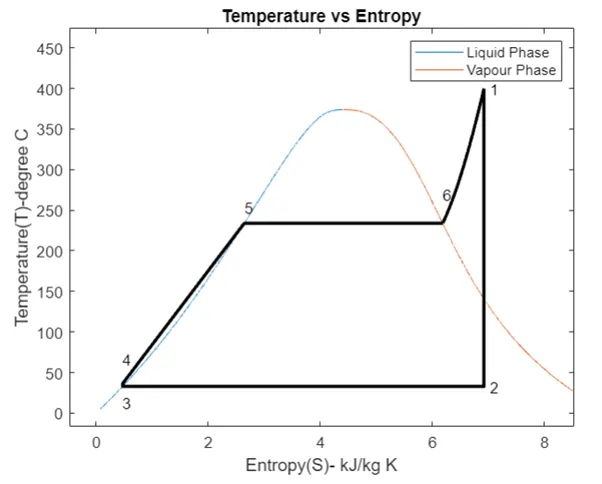
Then the curve of T-S is plotted determining the  values of Entropy in the range of Tsat & T1 using linspace command
t=linspace(5,400,25000);
for i=1:length(t)
s(i)=Xsteam('sL_t',t(i));
S(i)=Xsteam('SV_t',t(i));
h(i)=Xsteam('hL_t',t(i));
H(i)=Xsteam('hV_t',t(i));
end

then the legends,title & axes are plotted

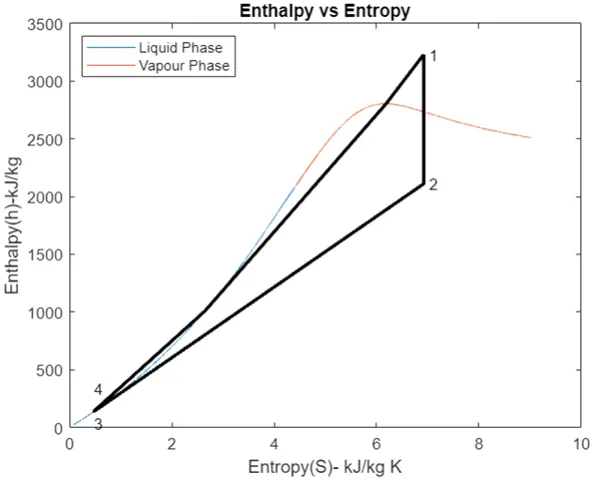
Simlarly Entalpy & Entropy values are calculated & plotted
Also other required values of Word done by turbine,work consumed by Pump,Heat added in Boiler,hear rejected in Condesnor,Net Work done,Efficiency ,Specific steam consumption & Back work done are calulated.


MATLAB CODE FOR RANKINE CYCLE

clear all
close all
clc

disp('Rankine Cycle Simulator')
disp('process 1-2: Isentropic expansion in turbine ')
disp('process 2-3: constant pressure heat rejection in condenser')
disp('process 3-4: Isentropic Compression in pump')
disp('process 4-1: constant pressure heat addition in boiler')

% Intial data inputs
T1 = input('Enter the turbine inlet temp: ');
p1 = input('Enter the turbine inlet press: ');
p2 = input('Enter the turbine outlet press: ');


% State Point 1 parameters i.e Turbine Inlet
Tsat = Xsteam('Tsat_p',p1);
h1 = Xsteam('h_pt',p1,T1);
s1 = Xsteam('s_pt',p1,T1);

%State Point 2 parameters i.e Cond4enser Inlet
s2 = s1;
sf2 = Xsteam('sL_p',p2);
sg2 =Xsteam('sv_p',p2);

% s2=sf2+(x2*sfg2)
% Dryness fraction
x2 =(s2-sf2)/(sg2-sf2);

T2 =Xsteam('T_ps',p2,s2);
h2 = Xsteam('h_px',p2,x2);
hf2 =Xsteam('hL_p',p2);

% State Point 3 Parameters i.e Pump Inlet
p3 = p2;
T3 = T2;
s3 = sf2;
h3 = hf2;
T5 = Tsat;

% State Point 4 Parameters i.e Boiler Inlet
s4 = s3;
p4 = p1;
h4=Xsteam('h_ps',p4,s4);
cp=Xsteam('cp_ps',p4,s4);
cv=Xsteam('cv_ps',p4,s4);
c=cp/cv;
T4=T3*((p4/p3)^(c-1)/c)

% State Point 5,6 Parameters
T5=Tsat;
h5=Xsteam('hL_p',p1);
s5=Xsteam('sL_p',p1);
T6=T1;
h6=Xsteam('hV_p',p1);
s6=Xsteam('sV_p',p1);

% Plotting T-S Diagram
t=linspace(5,400,25000);
for i=1:length(t)
s(i)=Xsteam('sL_t',t(i));
S(i)=Xsteam('SV_t',t(i));
h(i)=Xsteam('hL_t',t(i));
H(i)=Xsteam('hV_t',t(i));
end
figure(1)
plot(s,t);
hold on
plot(S,t);

plot([s1,s2,s3,s4,s5,s6],[T1,T2,T3,T4,T5,Tsat],'linewidth',2,'color','k');
text(s1+0.1, T1, '1')
text(s2+0.1, T2, '2')
text(s3, T3-20, '3')
text(s4, T4+20, '4')
axis([1,10,10,500]);


% Plotting Saturated Temperature
a=linspace(Tsat,T1,500);
for i=1:length(a)
    d(i)=Xsteam('s_pt',p1,a(i));
end
plot(d,a,'linewidth',2,'color','k')
title('Temperature vs Entropy')
xlabel('Entropy(S)- kJ/kg K')
ylabel('Temperature(T)-degree C')
legend('Liquid Phase','Vapour Phase')


figure(2)
plot(s,h);
hold on
plot(S,H);

plot([s1,s2,s3,s4,s5,s6,s1],[h1,h2,h3,h4,h5,h6,h1],'linewidth',2,'color','k');
text(s1+0.1, h1, '1')
text(s2+0.1, h2, '2')
text(s3, h3-100, '3')
text(s4, h4 +200, '4')
title('Enthalpy vs Entropy')
xlabel('Entropy(S)- kJ/kg K')
ylabel('Enthalpy(h)-kJ/kg')
legend('Liquid Phase','Vapour Phase','location','northwest')

% Result to be displayed in the command window
disp(' The following are the results of rankine cycle operation ')
disp(' ')
disp(' At the state point 1')
disp(' ')
n1=sprintf('p1 is %.2f bar',p1);
disp(n1)
n2=sprintf('T1 is %.2f Deg Celcius',T1);
disp(n2)
n3=sprintf('h1 is %.2f kJ/kg',h1);
disp(n3)
n4=sprintf('s1 is %.2f kJ/kgK',s1);
disp(n4)

disp(' ')
disp(' At the state point 2')
disp(' ')
n5=sprintf('p2 is %.2f bar',p2);
disp(n5)
n6=sprintf('T2 is %.2f Deg Celcius',T2);
disp(n6)
n7=sprintf('h2 is %.2f kJ/kg',h2);
disp(n7)
n8=sprintf('s2 is %.2f kJ/kgK',s2);
disp(n8)

disp(' ')
disp(' At the state point 3')
disp(' ')
n9=sprintf('p3 is %.2f bar',p3);
disp(n9)
n10=sprintf('T3 is %.2f Deg Celcius',T3);
disp(n10)
n11=sprintf('h3 is %.2f kJ/kg',h3);
disp(n11)
n12=sprintf('s3 is %.2f kJ/kgK',s3);
disp(n12)

disp(' ')
disp(' At the state point 4')
disp(' ')
n13=sprintf('p4 is %.2f bar',p4);
disp(n13)
n14=sprintf('T4 is %.2f Deg Celcius',T4);
disp(n14)
n15=sprintf('h4 is %.2f kJ/kg',h4);
disp(n15)
n16=sprintf('s4 is %.2f kJ/kgK',s4);
disp(n16)

% Workdone by turbine

W_D_T = h1-h2

% Workdone by the pump

W_D_Pump = h4-h3

%net workdone

W_D_Net = W_D_T-W_D_Pump

% Heat Supplied
q = h1-h4;

% Effeciency
n = W_D_Net/q

% Specific steam consumption
ssc = 3600/W_D_Net

% Back Work Ratio
BWR = W_D_Pump/W_D_T
Probable Queries & Answers: -
- Why we are calculating the temperature at point 4 by suing the equation cp/cv=gamma rather than t_ps (calculating the same from steam table)?
Answer: - Since the process is isentropic (entropy is fixed) & temperature is changing due to heat addition, so we use
P1v1=p2v2=
Cp=specific heat capacity of a substance at constant pressure.
It is the amount of heat energy released or absorbed by a unit mass of the substance with the change in temperature at constant pressure. In other words, under a constant pressure, it is the heat energy transfer between system & its surroundings. So, Cp represents molar heat capacity, C when pressure is constant.
The change in temperature will always cause a change in the enthalpy of the system
So is the heat energy absorbed or released by the system. Also, enthalpy change occurs during the change of phase or state of a substance.
Where Cp represents the specific heat at constant pressure
dH is the change in enthalpy
dT is the change in temperature
Cv=specific heat capacity of substance at constant volume.
It is the amount of heat energy absorbed/released per unit mass of a substance where volume does not change.
In other words,
Cv is the heat energy transfer between system & its surroundings without any change in the volume of the system.
Cv represents the molar heat capacity when volume is constant. Under a constant volume, the volume of a substance does not change, so the change in volume is zero.
Where Cv represents the specific heat at constant volume
dU is the small change in internal energy of the system,
dT is the change in temperature
Cp / Cv is known as heat capacity ratio.
The isentropic expansion factor is another name for heat capacity ratio that is also denoted for an ideal gas by gamma.
Therefore, Cp /Cv = gamma
Cp-Cv=R (gas constant)
Heat Capacity = Heat absorbed by a material / change in temperature