Project - 2 - Meshing on the suspension Assembly
AIM
- For the given assembly, check for the geometrical errors
- Mesh with the given element Quality criteria
- Use tetra elements to model non-uniform thickness components
- Diploy Appropriate connections to connect the component
SUSPENSION
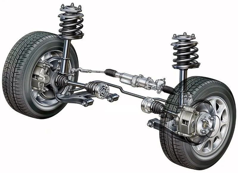
In a nutshell, your car’s suspension system is a protective lattice of shock-absorbing components such as springs and dampers. Your car’s suspension helps ensure that your drive is safe and smooth by absorbing the energy from various road bumps and other kinetic impacts. Furthermore, it helps your tires stay in contact with the road by increasing tire friction.
Think of the suspension of your car as a kind of carriage on which the car’s main cabin sits. Your cabin is made more comfortable because it is sitting on the suspension, which is connected to the car’s wheels. The vehicle and its cabin are insulated against impacts that are common when driving, even on well-paved roads.
The main parts of a car’s suspension include:
- Springs, which help to control the height and load of the suspension and cabin
- Shocks (also called dampers), which absorb and dampen various kinetic energy impulses that your tires transmit when they contact the road
-
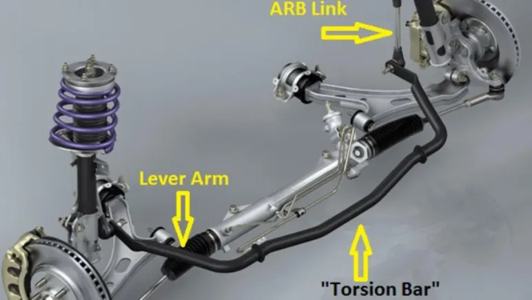
An anti-sway bar. The anti-sway bar can help to shift the movement of your wheels relative to your steering wheel. It effectively stabilizes your car’s direction as it moves along the road.
USE OF SUSPENSION
- Suspension systems maximize the friction between your car's tires and the road. By maximizing friction, you can steer your vehicle with more stability and experience more comfortable handling. The more contact your tires have with the road, the safer and more securely you'll be able to drive.
- The suspension system of your car also provides added comfort. By limiting the kinetic energy transferred from road imperfections like bumps to your cabin, you’ll bounce up and down far less, and your passengers will also enjoy a smoother ride.
- Furthermore, suspension systems can help to increase the lifespan and durability of your car. Your vehicle’s components will be taxed much less over time by limiting how much energy is transferred from bumps and potholes in the road. Therefore, your car’s other components will last longer.
PROCEDURE
I import the given model in to ansa,initially the given model is as shown
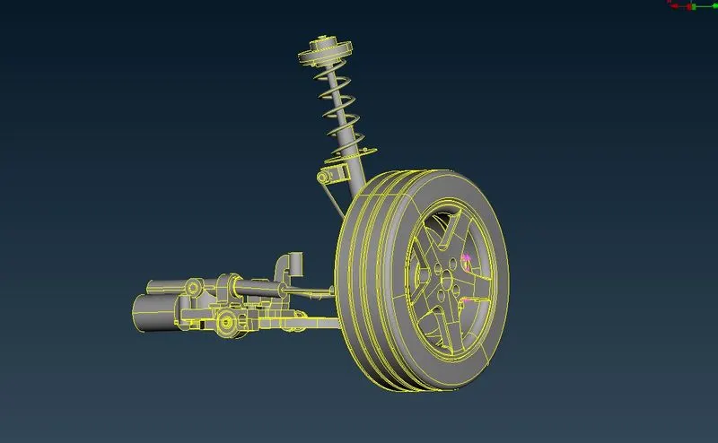
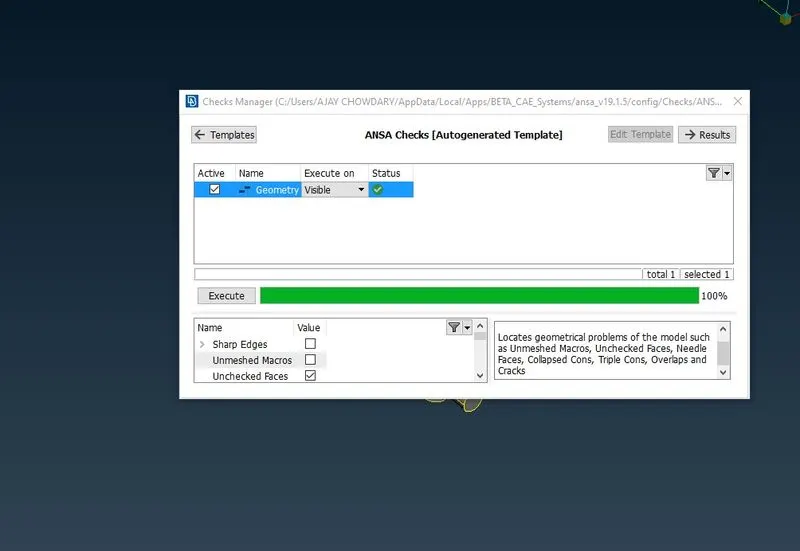
Now i run geometrical check to check for geometrical eerors
checks manager-->geometry checks
cleared the checks by using auto fixing available in checks manager
MESHING
For uniform thickness Entities we perform 2D meshing
2D MESHING
There are two types of two-dimensional cell shapes that are commonly used. These are the TRIANGLES and the QUADRILATERALS Computationally poor elements will have sharp internal angles or short edges or both
for uniform thickness entities I had extracted mid surfaces and meeshed the entities with the given quality and mesh criteria
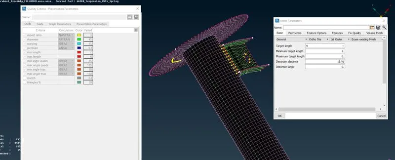
For non uniform thickness entities I used 3D meshing
3D MESHING & UNSTRUCTURED VOLUME MESH
3D MESHING
The basic 3-dimensional element are the tetrahedron, quadrilateral pyramid, triangular prism, and hexahedron. They all have triangular and quadrilateral faces.
UNSTRUCTURED VOLUME MESH
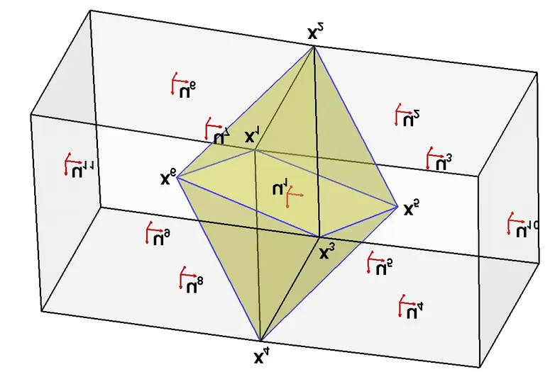
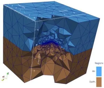
MESH PARAMETERS &QYALITY CITERIA
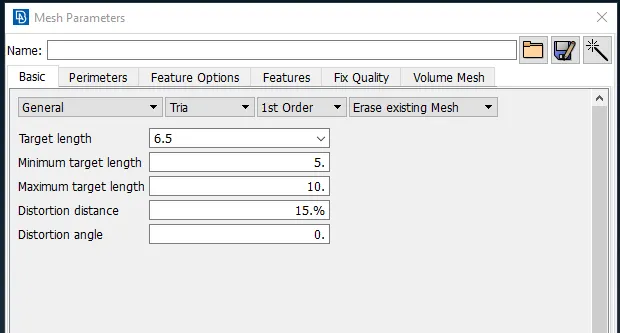
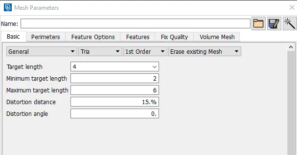
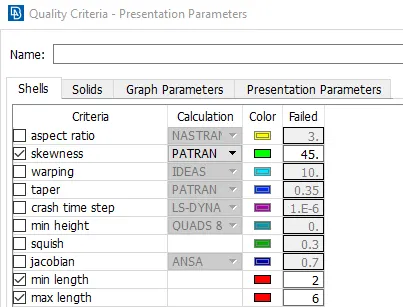
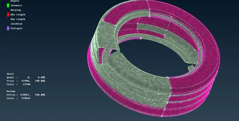
For Tyre and Rim mesh parameters given are
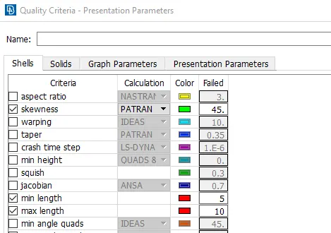
MESH PARAMETERS QUALITY CRITERIA
 +
+
OTHER NON UNIFORM THICKNESS ENTITIES
VOLUME MESH QUALITY PARAMETERS
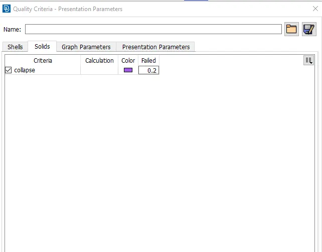
By using these parameters i run batch meshing for Tyre and Rim and other non uniform entities
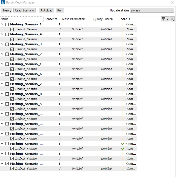
BATCH MESHINHG
Batch meshing is the process of autometic mesh generation as per given mesh and quality parameters
step 1-->Intially we need assaign the part in the model browser
step 2-->create a meshing scenario in batch meshing manager
step 3-->I assigned part in the contents present in batch meshing manager
step 4-->Run the meshing
Meshing is done by using spot mesh in the mesh module present in ansa where mesh flow and mesh quality are not fine
mesh module-->mesh generation-->spot mesh
CLEARING QUALITY
I clered all quality failures by using recontruction and smmothing tools avilable in mesh module
mesh module-->shell mesh-->reconstruct
mesh module-->shell mesh-->smooth
and some qualities are clered by using mvfree and mvsurf present in mesh module
mesh module-->grids-->mvsurf
mesh module-->grids-->mvfree
VOLUME MESH
I volume meshed the non uniform entities using volume mesh module present in ansa
STEPS
I defined the parts to volume mesh by using autodetect present in the volume mesh module
v.mesh-->volumes-->define
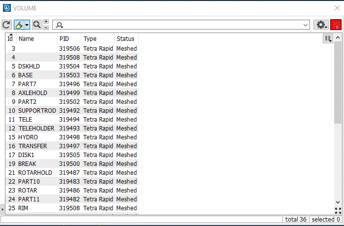
after defining the parts i moved to the list tool present in volumes
v.mesh-->volumes-->list
here we can see all the defined parts for volume meshing
i used tetra elements to create volume mesh by using remesh present in type in list
v.mesh-->volumes-->list(type-->remesh)
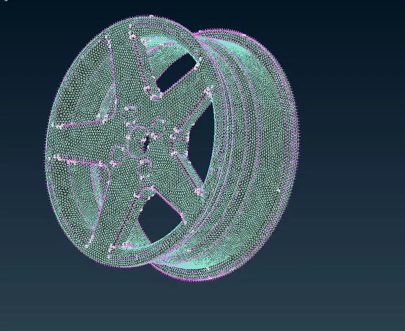
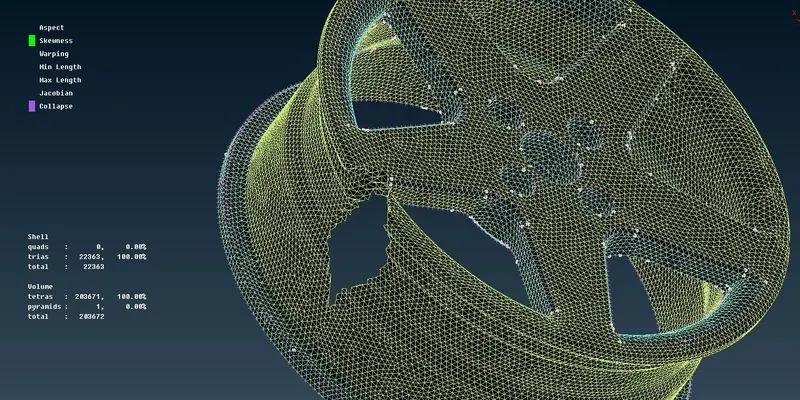
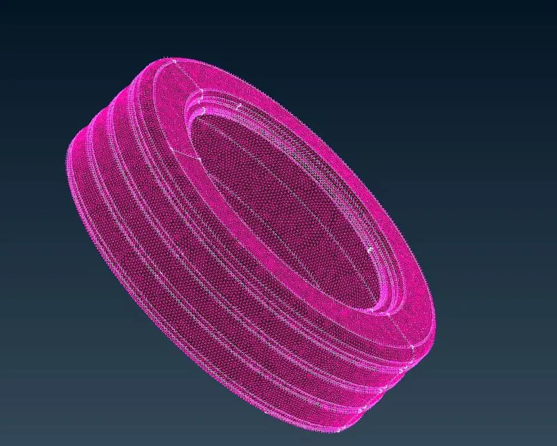
i used tetra rapid for volumetric meshing of the entities
TYRE & RIM
SPRING
Springs: There are three different spring types that are used in suspension systems: coil, leaf and torsion bar. Coil springs are merely wound torsion bars. Leaf springs serve as both the damping member and the linkage. Torsion bars rely on the twist of a long bar to provide a spring rate to dampen car shock loading.
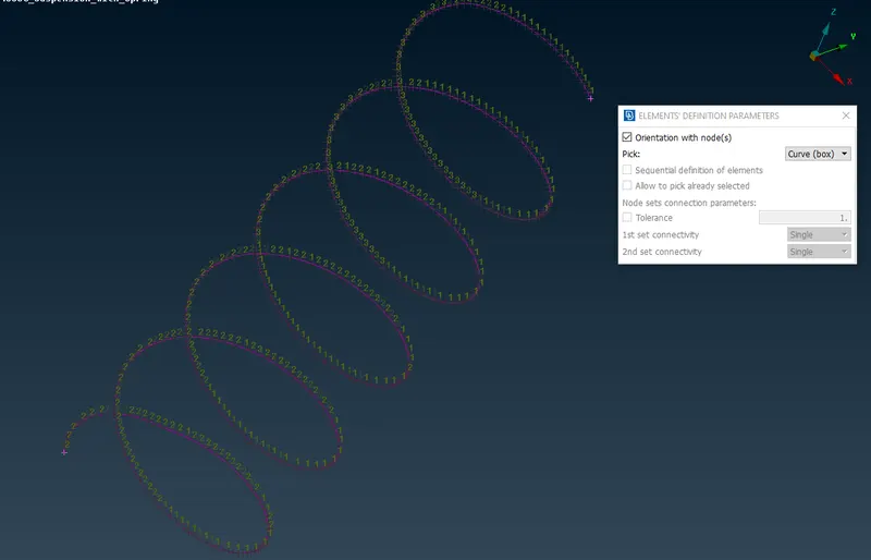
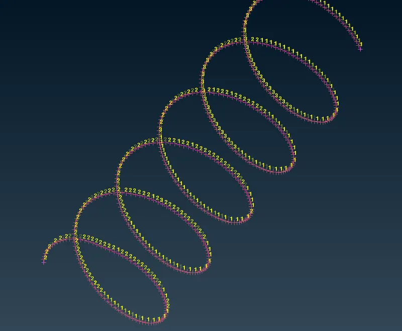
Springs can be represented as CBAR in ansa which is present in NASTRAN module
STEPS
step 1-->take the middle curve for the spring
step 2-->create a COG for the middle curve taken
step 3-->select CBAR in nastran module and select the curve
step 4-->define element length
step 5-->define diameter/Radius
step 6-->define pid
SWAY BARS OR ANTI ROLL BARS
An anti-roll bar (roll bar, anti-sway bar, sway bar, stabilizer bar) is a part of many automobile suspensions that helps reduce the body roll of a vehicle during fast cornering or over road irregularities. It connects opposite (left/right) wheels together through short lever arms linked by a torsion spring.
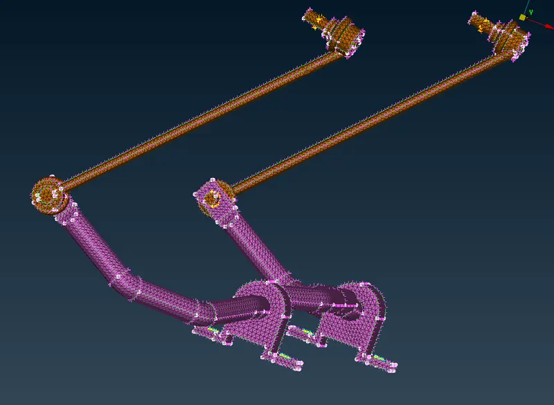
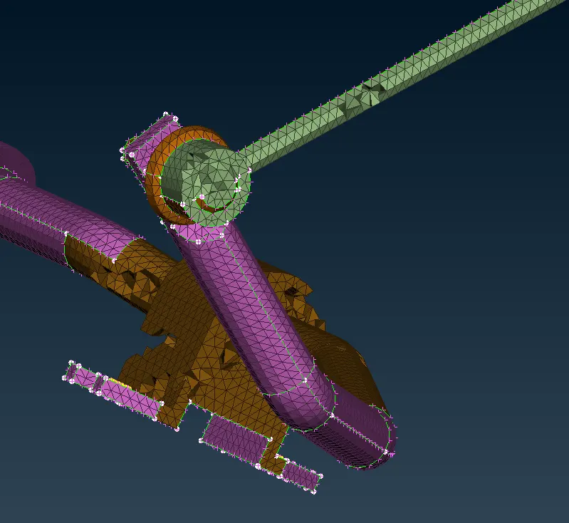
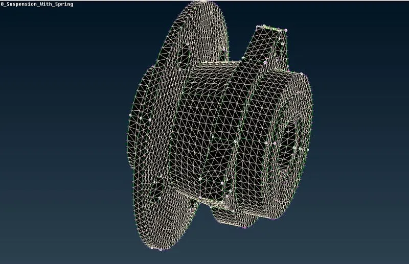
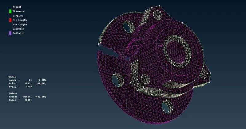
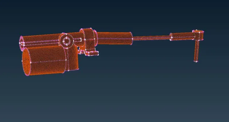
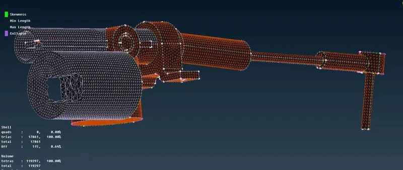 similarly remaining parts are meshed
CONNECTIONS
necessary connections are diployed using connection manager and nastran module
diployed conectins by using cluster RBE2
nastran-->elements-->RBE2-->many node RBE2/two node RBE2
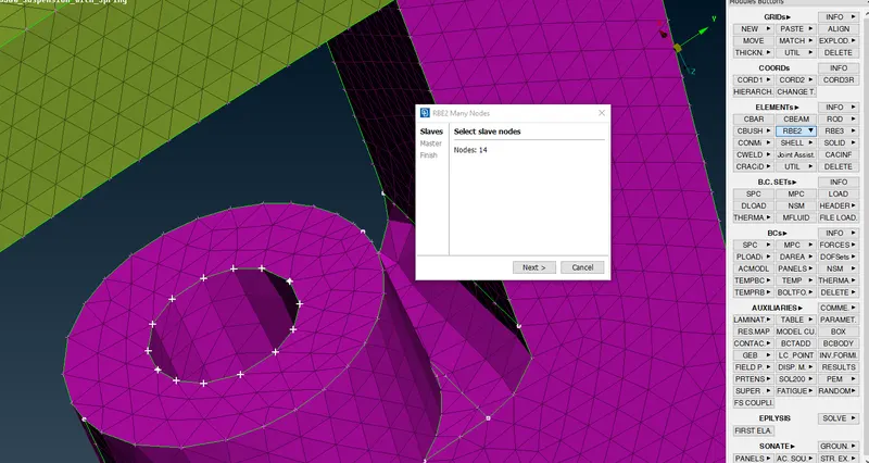
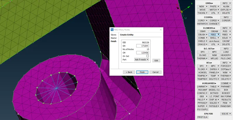
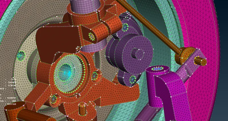
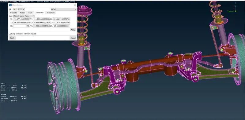
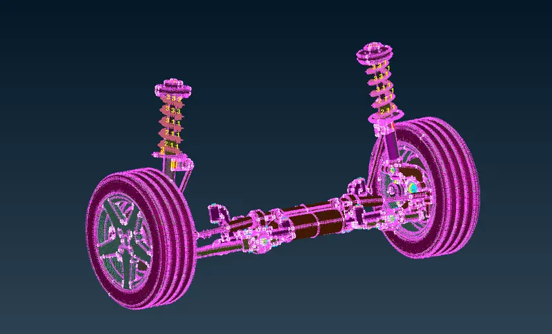
All the entities are mirrored so as to form full front suspention by usin transform tool
transform-->copy-->symmetry-->mirror 3 point plane
LEARNING OUTCOMES
i have learned how to determine the element type to mesh
learned different methods of clearing the qualities for given quality critiria
learned different approaches to mesh the component for better mesh flow
learned to diploy different type of connections
CONCLUSION
In this project i had done topology,cleanup and done meshing and achived better mesh flow and i cleared failing elements quality citeria i had created volume mesh for non uniform thickness entities and 2d mesh for uniform thickness entities and diployed connections for two different entities