Project - 2 - Meshing on the suspension Assembly
Aim: Meshing of Suspension assembly
Theory:
Suspension is the system of tires, tire air, springs, shock absorbers and linkages that connects a vehicle to its wheels and allows relative motion between the two. Suspension systems must support both road holding/handling and ride quality, which are at odds with each other. The tuning of suspensions involves finding the right compromise. It is important for the suspension to keep the road wheel in contact with the road surface as much as possible, because all the road or ground forces acting on the vehicle do so through the contact patches of the tires. The suspension also protects the vehicle itself and any cargo or luggage from damage and wear.
Objective:
For the given assembly, check for the geometrical errors and mesh with the given element Quality criteria. After meshing the component the thickness has to be assigned for mid surfaces. Use tetra elements to model non-uniform thickness components. Also use Appropriate connections to connect the component as suggested in the Project-2 video (Use PBAR elements to model suspension spring). At last perform Symmetry command to reflect the half finished model to the other side.
Parent geometry:
Import the model as step file inside the ANSA workbench
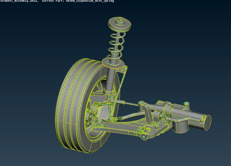
fig 1
Perform topological check from the cons module.
Set different property ID as shown below
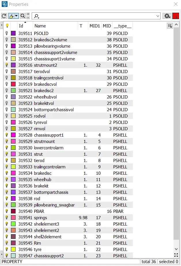
fig 2
2D meshing surfaces:
Extract the features which are less than 5mm
2D mesh overview of the surfaces according to the criteria given
|
S.No |
Quality Criteria |
Value |
|
1 |
Target/Average length |
4 |
|
2 |
Minimum Length |
2 |
|
3 |
Maximum Length |
6 |
|
4 |
Aspect |
3 |
|
5 |
Warpage |
15 |
|
6 |
Skewness |
45 |
|
7 |
Jacobian |
0.7 |
|
8 |
Minimum Quad Angle |
45 |
|
9 |
Maximum Quad Angle |
135 |
|
10 |
Minimum Tria Angle |
30 |
|
11 |
Maximum Tria Angle |
120 |
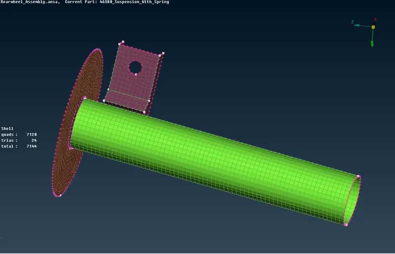
fig 3
Spring FEA modelling:
Generate a middle curve for the spring
Create cog point for the curve
Select CBAR element from Nastran deck and select the curve
Specify the element length and create a new PID
Define the radius and area of the spring and represent it a mesh.
The mesh model of spring is given below
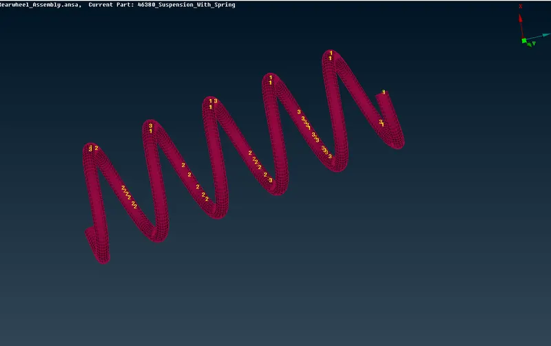
fig 4
Volumetric mesh:
Go to volume mesh tab
Select define option, choose manual and select the entity.
Define list, right click to remesh and choose tetra rapid algorithm and apply.
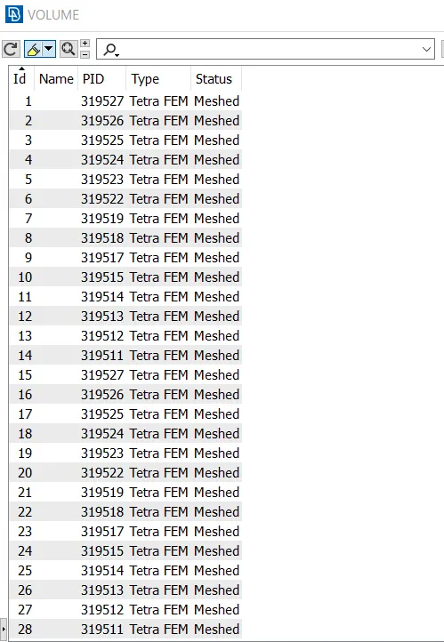
fig 5
Some volume mesh features are given below
Tyre
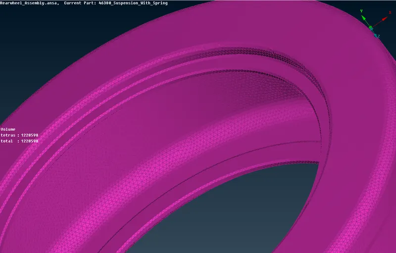
fig 6
Rim
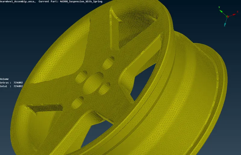
fig 7
Tie rod
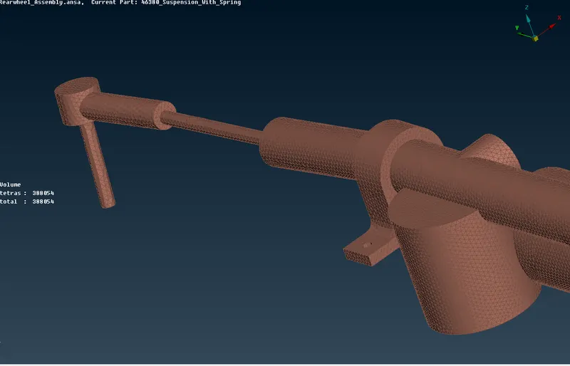
fig 8
Rod
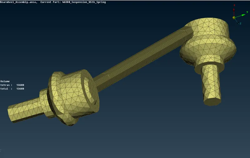
fig 9
Pillow bearing
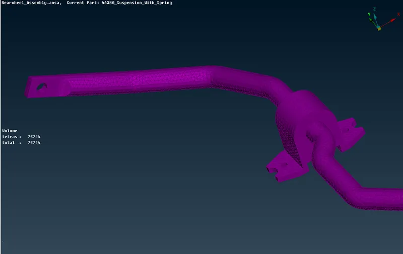
fig 10
Brake disc
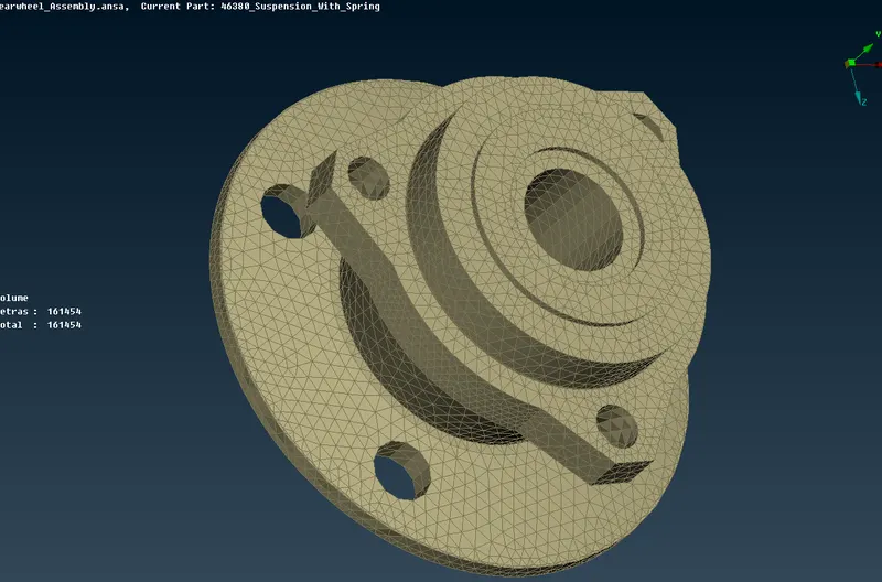
fig 11
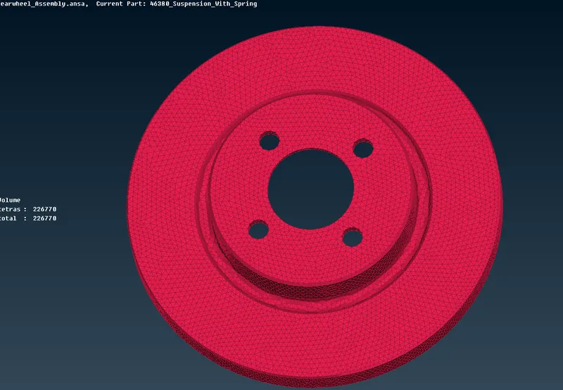
fig 12
Strut mount
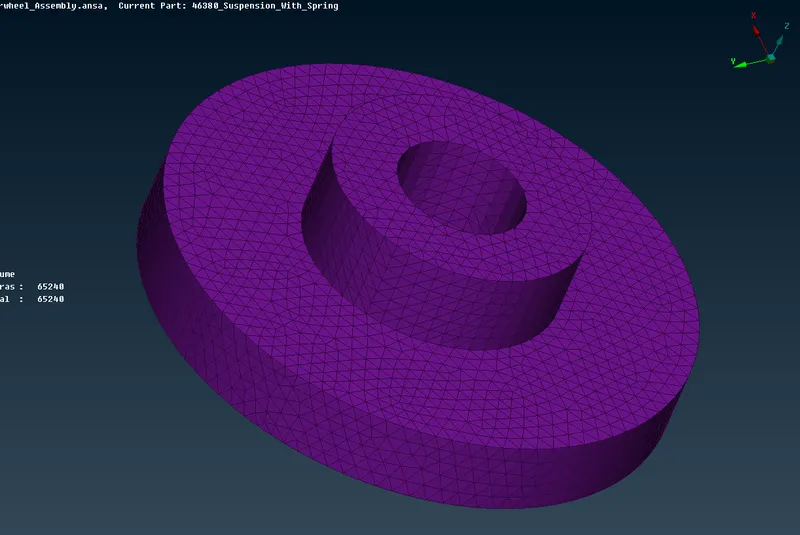
fig 13
Wheel hub
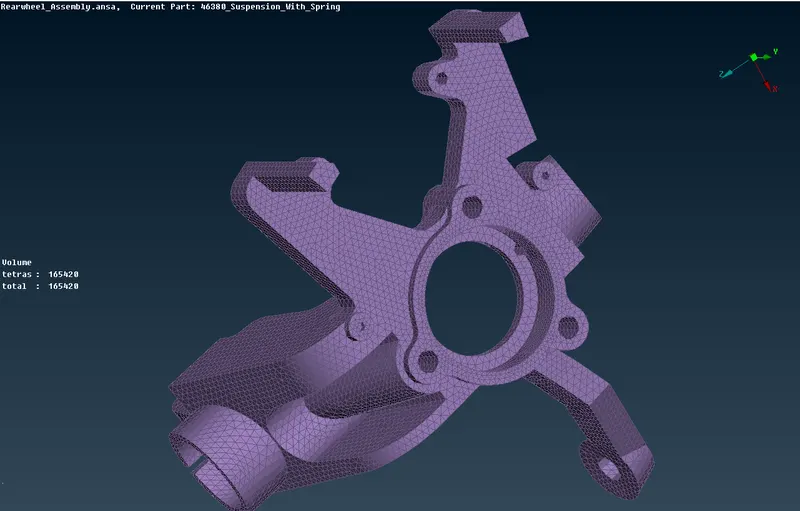
fig 14
Bottom chassis
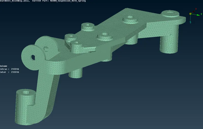
fig 15
Brake kit
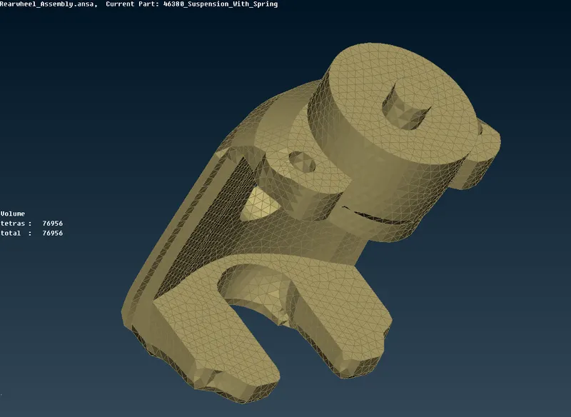
fig 16
Trailing control arm
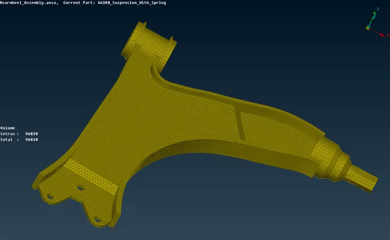
fig 17
Chassis support
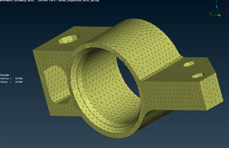
fig 18
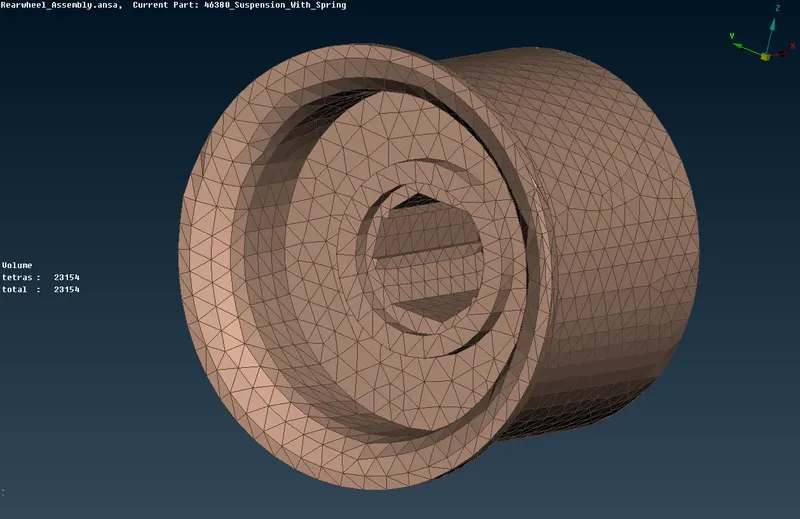
fig 19
Connections:
Connections are provided in the regions of bolt areas as RBE2 CONNECTIONS.
Go to Nastran deck module.
Select RBE2 with many nodes option
Select the neighboring node of two entities
Apply and realize the connection
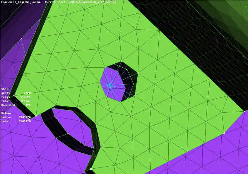
fig 20
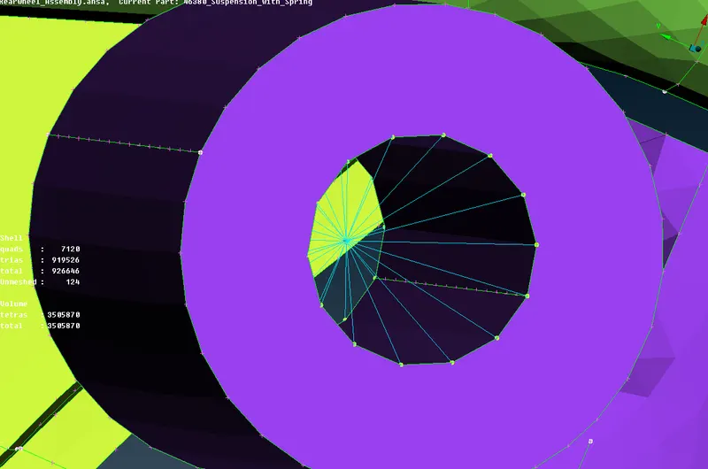
fig 21

fig 22
Performing symmetry operation on the FEA MESH MODULE
Go to copy option and select the entire entity to be performed mirror operation.
Select the symmetry option with 3point mirror plane
Choose 3 points and then apply.
The symmetry option will be performed.
The fig below shows the complete model view of the suspension assembly system
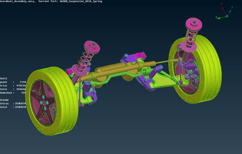
fig 23