Project - 2 - Meshing on the suspension Assembly
File Link :
https://drive.google.com/file/d/1zpe4GRFJlbmCmhs6pfrkoP_KXM_Wf6GF/view?usp=sharing
Aim:
Project-2
For the given assembly, check for the geometrical errors and mesh with the given element Quality criteria. After meshing the component, the thickness has to be assigned for mid surfaces. Use tetra elements to model non-uniform thickness components. Also, use Appropriate connections to connect the component as suggested in the Project-2 video (Use PBAR elements to model suspension spring). At last, perform the Symmetry command to reflect the half-finished model to the other side.
Write a detailed report on your meshing process and also mention which method you used to extract the mid-surface along with the reason.
Common Note:
- Use Volume mesh for Tyre and Rim with the below Quality criteria. (Use Tria Element)
- Use mid surface only when the thickness is uniform and less than 5 mm. (Use Mixed elements)
Quality Criteria for Surface Meshing of Tyre and Rim (Element type: Tria):
|
S.No |
Quality Criteria |
Value |
|
1 |
Target/Average length |
6.5 |
|
2 |
Minimum Length |
5 |
|
3 |
Maximum Length |
10 |
|
4 |
Skewness |
45 |
Quality criteria for Surface Meshing of Non-Uniform thickness components other than Tyre and Rim (Element type: Tria):
|
S.No |
Quality Criteria |
Value |
|
1 |
Target/Average length |
4 |
|
2 |
Minimum Length |
2 |
|
3 |
Maximum Length |
6 |
|
4 |
Skewness |
45 |
Quality Criteria for Volume meshing of all Non-Uniform thickness components (Element type: Tetra Elements):
|
S.No |
Quality Criteria |
Value |
|
1 |
Tet-collapse |
0.2 |
Quality criteria for Mid surfacing of Uniform thickness part which has a thickness less than 5 mm (Element type: Mixed elements):
|
S.No |
Quality Criteria |
Value |
|
1 |
Target/Average length |
4 |
|
2 |
Minimum Length |
2 |
|
3 |
Maximum Length |
6 |
|
4 |
Aspect |
3 |
|
5 |
Warpage |
15 |
|
6 |
Skewness |
45 |
|
7 |
Jacobian |
0.7 |
|
8 |
Minimum Quad Angle |
45 |
|
9 |
Maximum Quad Angle |
135 |
|
10 |
Minimum Tria Angle |
30 |
|
11 |
Maximum Tria Angle |
120 |
Procedure:
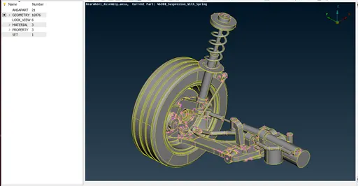
- Import Model
Open the given model (Rearwheel_Assembly.ansa) in ANSA
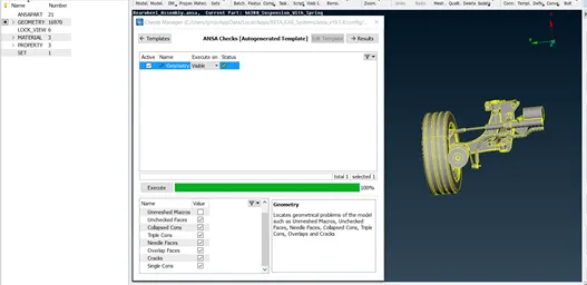
- Geometry Clean up
The components are checked for geometry clean-up using Checks > Geometry and clean up the errors using auto fix and use topo tools like new face, delete and topo etc. to achieve 100%.
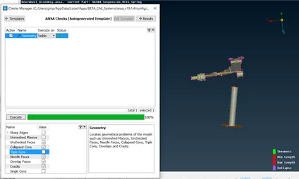
- Mid Surface Extraction for the components having a thickness less than 5mm.
Mid Surface is extracted by Offset>Faces by selecting the faces of the components.
Also, Mid-Surface > Skin is used to extract mid surface.
Then these mid surfaces are assigned with properties like Thickness using Set PID.
Mid Surface Geometry is also checked and cleaned up before meshing.
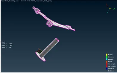
Meshing
By adding the selected component in ANSAPART, using Batch Meshing (Mid -Surface) by setting the Mesh Parameters and Quality Criteria, given surfaces are meshed.
Further failed elements and trias are removed using Split, Swap, Join (Elements Tab), Smooth (Shell mesh tab), Paste (Grids) and Num +/- (perimeter tab).
- Meshing of Tyre & Rim
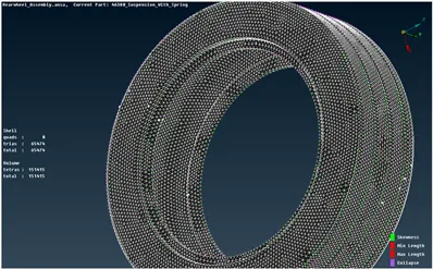
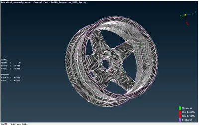
Surface Meshing
Add the Tyre and Rim separately in ANSAPART.
Create Meshing Scenarios in batch each for Tyre and Rim setting the Mesh Parameters and Quality Criteria as follows
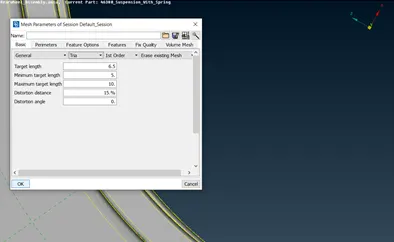
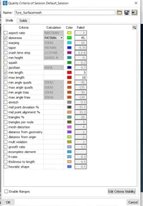
After running the meshing scenarios, some elements don’t satisfy the criteria
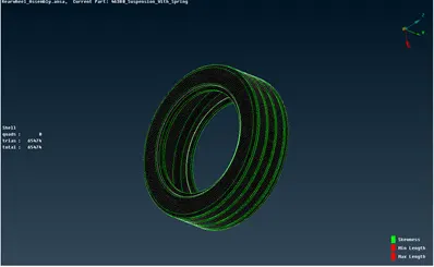
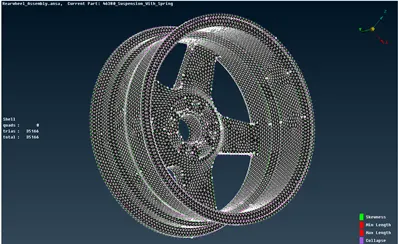
So, Mesh Quality is improved using reconstruct option in Shell mesh -> reconstruct option also Split option is used.
Tyre:
Rim:
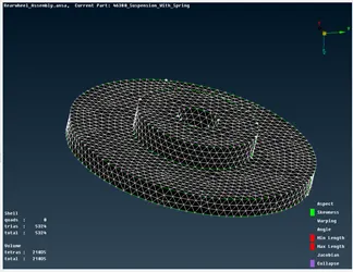
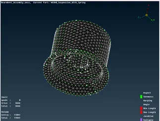
Volume meshing:
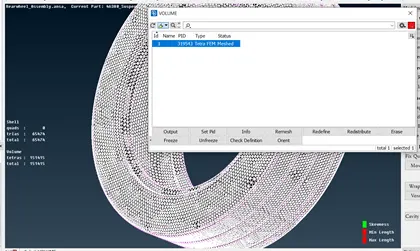
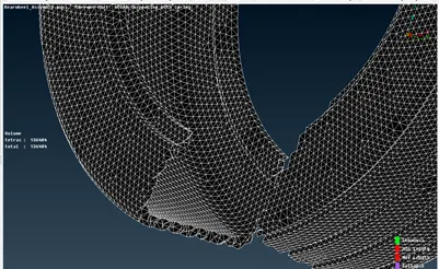
Define the volumes of Tyre and rim in Volume Mesh manually, then in the list select the volume and re-mesh it using Tetra FEM.
Check for the tet-collapse errors. Failed 3d elements are fixed by fix quality (Improve tab of Volume Mesh) or using MV free (Grids tab of Mesh).
Tyre:
Rim:
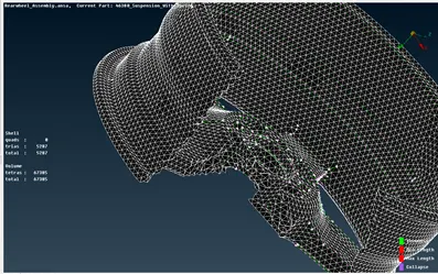
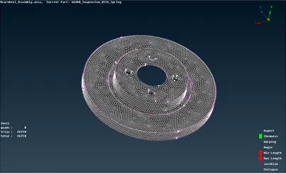
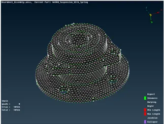
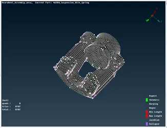
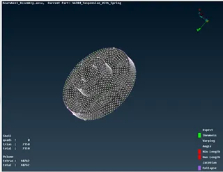
- Meshing of Non- uniform thickness Components (Suspension Assembly)
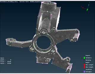
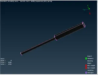
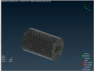
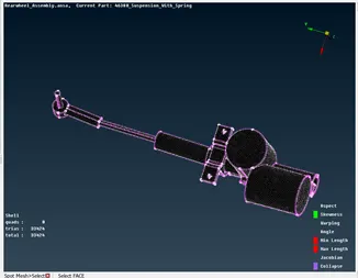
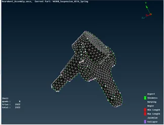
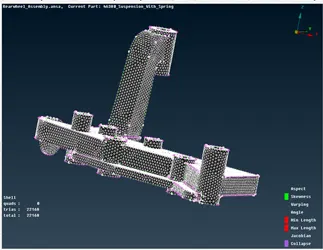
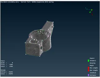
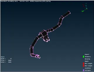
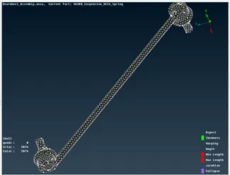
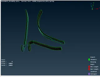
Surface Meshing
Add each of the Suspension Assembly components separately in ANSAPART.
Create Meshing Scenarios in batch for each component setting the Mesh Parameters and Quality Criteria as follows (save the file(surface mesh) and use it for subsequent runs)
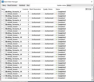
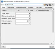
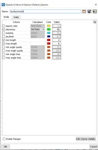
After running the meshing scenarios, some elements don’t satisfy the criteria
So, Mesh Quality is improved using reconstruct option in Shell mesh -> reconstruct option also Split option is used.
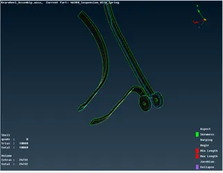
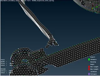
Volume meshing:
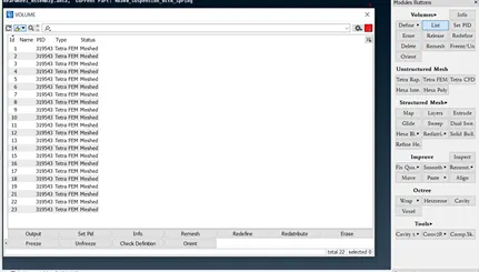
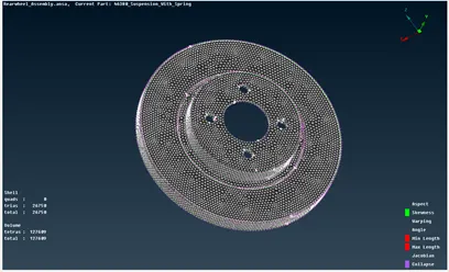
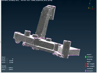
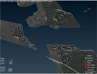
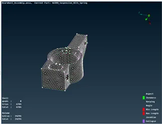
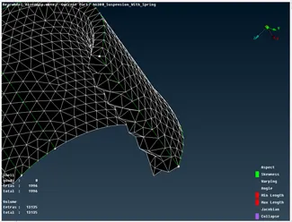
Define the volumes of each component in Volume Mesh manually, then in LIST select the volume and re-mesh it using Tetra FEM.
Check for the tet-collapse errors. Failed 3d elements are fixed by fix quality (Improve tab of Volume Mesh) or using MV free (Grids tab of Mesh).
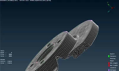
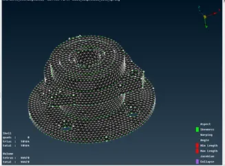
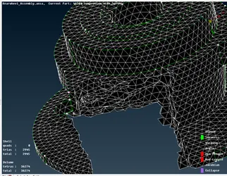
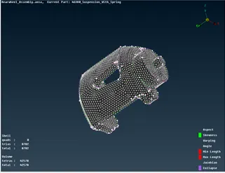
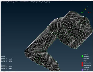
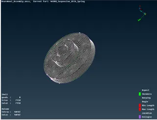
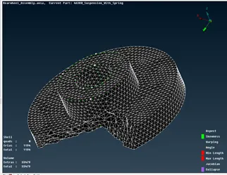
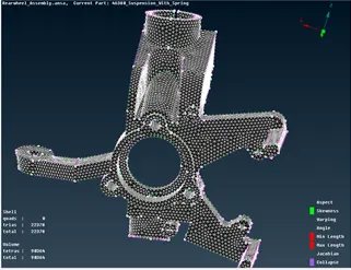
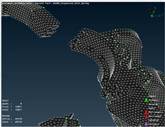
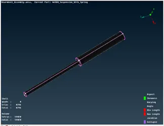
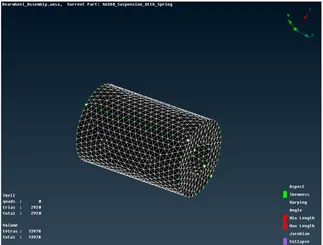
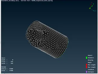
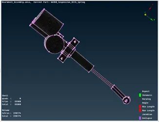
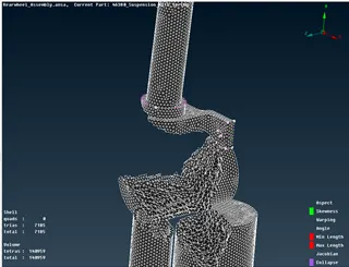
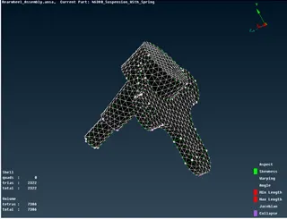
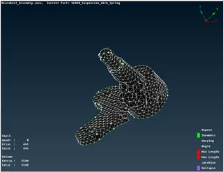
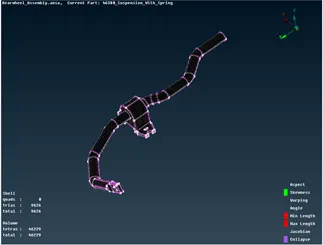
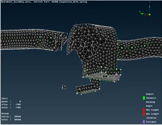
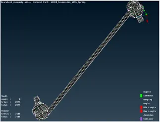
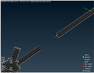
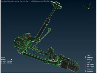
Full Suspension Assembly:
- Connections
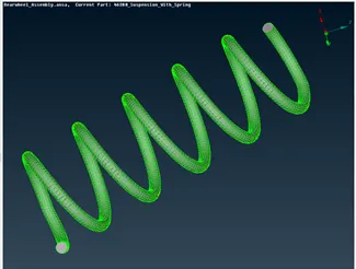
Spring in the component is represented as CBAR 1D Element.
Mid Curve is extracted using Curve > Middle for the spring, Then the curves are connected to form a single curve using Curves > Connect
And COG for the curve is defined.
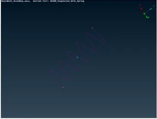
Using CBAR in NASTRAN deck, Check Orientation with nodes and Curves (box) and then select the curve and COG, give the element length as 4.
Set the PID using the Radius of the spring
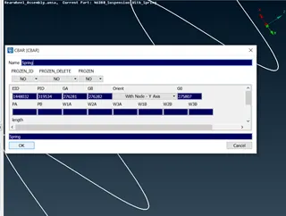
Spring is now represented as a 1D element.
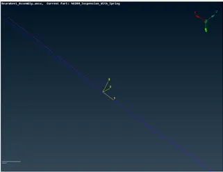
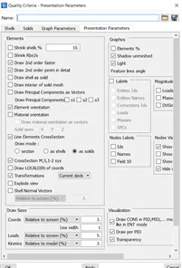
To see it the 3D representation of the spring Check the box of “Line Elements CrossSection” and select as Solids in Quality Criteria
Spring:
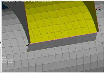
Seam Weld:
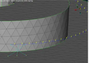
Create curve using Con2Curve by selecting the con where the seam weld is required, convert the curve to the seam line, then using connection select the seam line and give the required parameters like distance, P1, P2, Step size (element length) and width.
RBE2 Connections:
Suspension Assembly Components are connected with each other using Many Node RBE2 (holes) and Two Node RBE2 (Bolt) – connecting the master nodes of many nodes RBE2
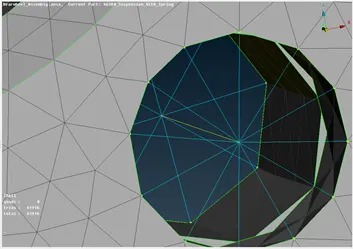
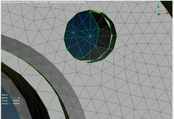
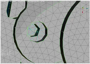
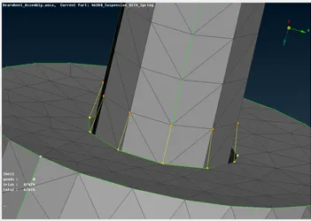
Spring is also connected to the component using Many node RBE2
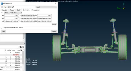
- Transform Symmetry
Using 3 point Mirror plane Symmetry, all entities are selected and copied/ transformed to complete the geometry.
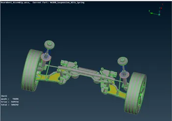
Final Model Image:
Learning Outcome:
Meshing the entire components of the suspension assembly – using various methods and criteria depending upon the component.
Connecting them through desired connections.
Speeding up the process using batch meshing to save time.
Conclusion:
Thus, the given component Rear Wheel Assembly is completed successfully satisfying all the given criteria.