Project - 2 - Meshing on the suspension Assembly
AIM : To achieve the good quality mesh of the given meshing of the Suspension Assembly by using ANSA tool, the procedure consists of Topo cleanup, Extracting the Mid surface for uniform thickness(<5mm), surface and volume meshing for non uniform thickness, Defeaturing and meshing by constraining the below parameters as inputs, appropriate connections and symmetry.
Quality Criteria for Surface Meshing of Tyre and Rim (Element type: Tria) :
|
S.No |
Quality Criteria |
Value |
|
1 |
Target/Average length |
6.5 |
|
2 |
Minimum Length |
5 |
|
3 |
Maximum Length |
10 |
|
4 |
Skewness |
45 |
Quality criteria for Surface Meshing of Non Uniform thickness components other than Tyre and Rim (Element type: Tria) :
|
S.No |
Quality Criteria |
Value |
|
1 |
Target/Average length |
4 |
|
2 |
Minimum Length |
2 |
|
3 |
Maximum Length |
6 |
|
4 |
Skewness |
45 |
Quality Criteria for Volume meshing of all Non Uniform thickness components (Element type: Tetra Elements):
|
S.No |
Quality Criteria |
Value |
|
1 |
Tet-collapse |
0.2 |
Quality criteria for Mid surfacing of Uniform thickness part which has thickness less than 5 mm (Element type: Mixed elements) :
|
S.No |
Quality Criteria |
Value |
|
1 |
Target/Average length |
4 |
|
2 |
Minimum Length |
2 |
|
3 |
Maximum Length |
6 |
|
4 |
Aspect |
3 |
|
5 |
Warpage |
15 |
|
6 |
Skewness |
45 |
|
7 |
Jacobian |
0.7 |
|
8 |
Minimum Quad Angle |
45 |
|
9 |
Maximum Quad Angle |
135 |
|
10 |
Minimum Tria Angle |
30 |
|
11 |
Maximum Tria Angle |
120 |
PROCEDURE:
Import the given suspension assembly Model into the Ansa, carefully study and understand the model.
A.TOPO CLEANUP
- Give the Topo command to entire Model assign the property index for each individual components /feature by selecting the faces and utilizing the Commands storage lock, OR, INOT , neighbour all.
- Now check for the Geometry checkup which is available Tools --> Check --> Geometry for Sharp edges, Unchecked Faces, Triple Cones, Cracks, Single Cones(which are missed in Topo during selection and neglect the outer perimeter single cones) , Needle faces,Overlap Faces.
- Fix the errors automatically by the FIX option. If any errors are not fix during the automatic, fix them manually especially triple cones by using the commands release, INOT, OR, neighbor all, Cut etc. which is useful to resolve the errors.
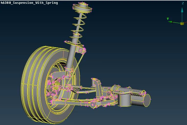
- Repeat the point no. 3 & 4 for all the individually property components which are stored in property index.
- After resolving all the issues, measure thickness randomly for all the individual parts and define them.
B. MIDSURFACE EXTRACTION
- Assign the Orient to all the components in the same direction for each property index. Develop the Mid surface by using the OFFSET command for all the components of property index and assign the offset value.
- Since there are many faces, to select the entire face activate crosshatch and keep the face selection in inclined feature area.
- Assign the property Index by using the storage lock for the each mid surface.
- Give Topo for the mid surface and check the geometry for error. Fix the errors automatic if any use the manual method as mentioned in TOPO cleanup for all the property features.
C. DE- FEATURING
- After mid surfacing, De-feature the midsurface without altering the Original Geometry size and shape.
- Defeature is defined as removing of additional curves, Hotpoint’s, cones which are used during the Modeling of geometry it can be done by using the commands such as number of Hotpoint’s (+/-), Cut, join, Delete , Hot points etc, whichever is used to defeature.
- Make suitable rectangular planes on the faces by using the command (Mesh -> Macros -> Project cut) to get suitable quads mesh in undisturbed and regular pattern. Delete the construction cons after completing the mesh by using the join option mentioning Reconstruction as keep in option list.
D. 2D MESHING FOR UNIFORM THICKNESS(<5mm)
- Enter the input constraints of mesh as given aim in the command (Utilities -> Mesh Parameters and Quality)
- Mesh the given mid surface by selecting the features separately and mesh by using command (Mesh -> Mesh Generation -> best).
- Use the command (Mesh -> Shell Mesh -> Reconstruction) to get the fine mesh without any errors.
- Refine the Mesh by using the Commands (Swap, Paste, Split, join, etc) to get the refine mesh and to avoid the opposite trias, rotating quads and trias at perimeter of features like hole, edge perimeter etc and resolve all the error in OFF of mentioned mesh parameters.
- After completing the Mesh, check the unmeshed areas if any and enable the thickness and enable the thickness Quality Criteria -> Presentation Parameters -> enable draw shell as solid
E. 2D MESHING FOR NON-UNIFORM THICKNESS & THICKNESS >5mm
2D MESHING
- Enter the input quality constraints of mesh as given aim in the command (Utilities ->Quality Criteria) especially Max. & Min. length respectively.
- Enter the input quality constraints of mesh as given aim in the command (Utilities -> Mesh Parameters ) especially target length, Mesh as trias respectively.
- Mesh the given all the curved and hole surfaces by selecting the features separately and mesh by using command (Mesh -> Mesh Generation -> Spot mesh -> Ortho Trias).
- Mesh the given all the flat surfaces by selecting the features separately and mesh by using command (Mesh -> Mesh Generation -> Spot mesh -> Trias).
- Use the command (Mesh -> Shell Mesh -> Reconstruction) to get the fine mesh without any errors.
- If any errors (OFF elements) Refine the Mesh by using the Commands (Grids move ,Swap, Paste, Split, join, etc) to get the refine mesh.
3D ( Volume) MESHING
- Go to the volume deck , assign and define the volume property index for all the features individual.
- Enter the input quality criteria of collpase in solid mesh (Utilities ->Quality Criteria -> Collapse).
- Mesh the all volumes each individually by using Tetra Rapid or Tetra FEM algorithm.
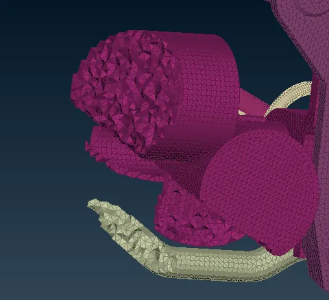
- Check the collpase criteria if any OFF elements. Resolve all the off elements by using the MV Free/Fix Quality.
E. CONNECTIONS
- After completion of entire meshing all PIDs, carefully study and understand the connection between the different PIDs in model.
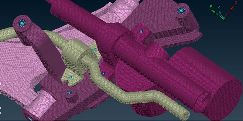
- Check for the unmeshed surface if any unmeshed surface, mesh the same.
- Give the connections over the surface as RBE 2 Cluster rigid in nastran deck, where ever the bolts holes between two surfaces or weight reducing holes or connections between the shafts are required in components by selecting the closed loop nodes which are constrained to all DOF.
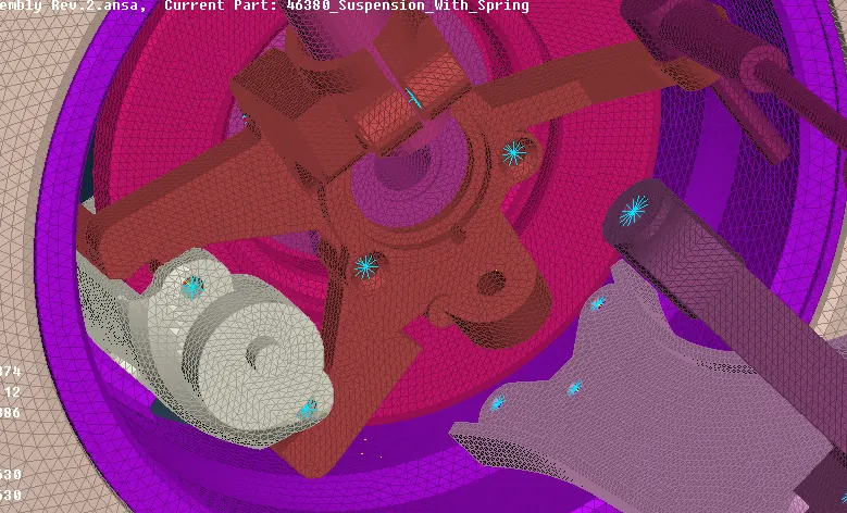
4. Give the symmetry to entire model by using 3 point symmetry.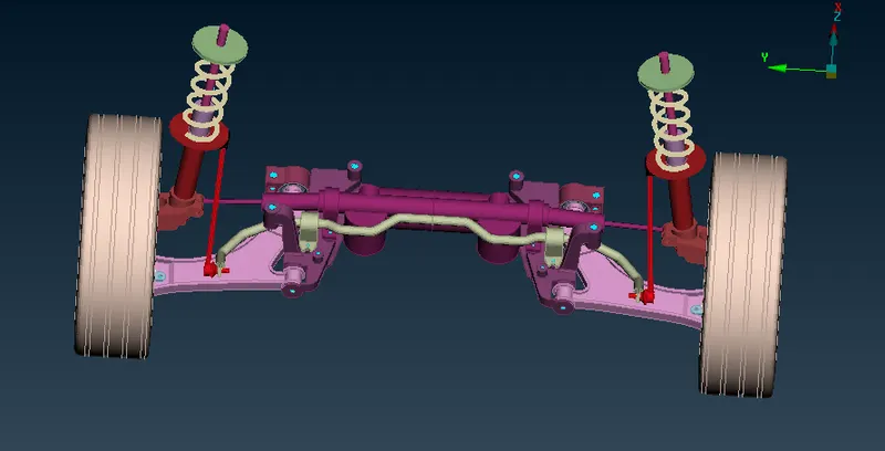
Learning Outcomes:
- A Clear understanding on meshing and Ansa tool in especially working on suspension assembly with many Property Index.
- Complications of Extracting the Midsurface in suspension assembly where feature dimensions are very small and variation in thickness for single feature.
- Meshing effects of one feature with respective other which are attached together.
- A Clear understanding on Volume meshing and Ansa tool.
- Methodology on working on Trias & Ortho trias and working with Collapse quality.
- A Clear understanding on Connections and its types.
Result & Conclusion:
Attached Ansa file consists of final mesh and images are attached here.