Project - 2 - Meshing on the suspension Assembly
Aim: To perform meshing on rear suspension assembly by using below given Quality criteria
Objective: To use proper meshing option on each part and designing of 1D element
Quality Criteria for Surface Meshing of Tyre and Rim (Element type: Tria) :
|
S.No |
Quality Criteria |
Value |
|
1 |
Target/Average length |
6.5 |
|
2 |
Minimum Length |
5 |
|
3 |
Maximum Length |
10 |
|
4 |
Skewness |
45 |
Quality criteria for Surface Meshing of Non Uniform thickness components other than Tyre and Rim (Element type: Tria) :
|
S.No |
Quality Criteria |
Value |
|
1 |
Target/Average length |
4 |
|
2 |
Minimum Length |
2 |
|
3 |
Maximum Length |
6 |
|
4 |
Skewness |
45 |
Quality Criteria for Volume meshing of all Non Uniform thickness components (Element type: Tetra Elements):
|
S.No |
Quality Criteria |
Value |
|
1 |
Tet-collapse |
0.2 |
Quality criteria for Mid surfacing of Uniform thickness part which has thickness less than 5 mm (Element type: Mixed elements) :
|
S.No |
Quality Criteria |
Value |
|
1 |
Target/Average length |
4 |
|
2 |
Minimum Length |
2 |
|
3 |
Maximum Length |
6 |
|
4 |
Aspect |
3 |
|
5 |
Warpage |
15 |
|
6 |
Skewness |
45 |
|
7 |
Jacobian |
0.7 |
|
8 |
Minimum Quad Angle |
45 |
|
9 |
Maximum Quad Angle |
135 |
|
10 |
Minimum Tria Angle |
30 |
|
11 |
Maximum Tria Angle |
120 |
Procedure:
1.Geometry cleaning of the model was done as it was having needle faces and single cons
2.After cleaning the geomerty then the model was verified part by by part for volume and midusrface
3.The Parts with Non Uniform thickness were meshed with tetra mesh and futher volume was assigned
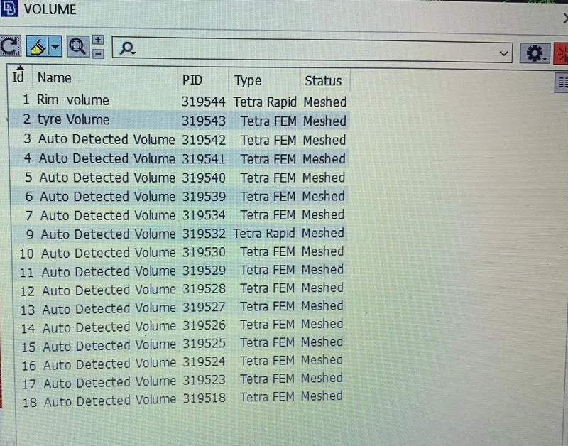
Fig : All Volumes of supension system including tyres and rims
4.First of all meshing was done on the tyre and RIM of the assembly and volume meshing was also done
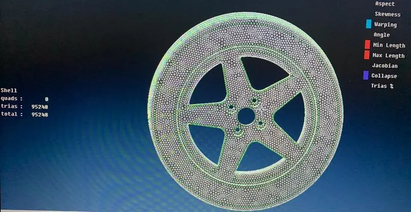
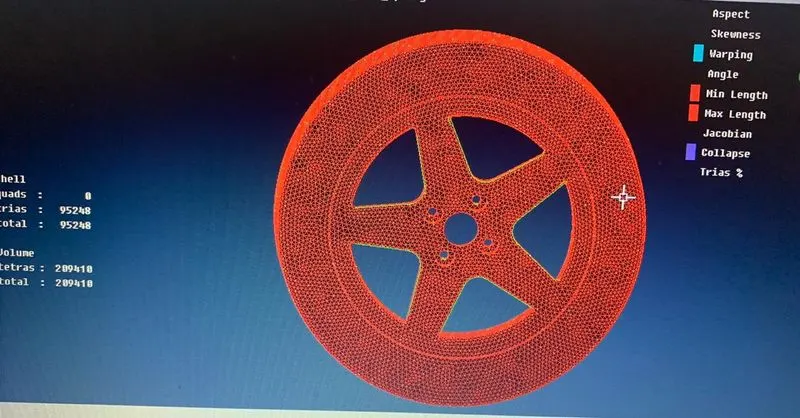
Fig: Meshing on tyre and rim Fig: Volume meshing on the Tyre and rim
5.Then after this meshing was done on the supension system which was having several parts and few parts were with uniform thickness for the parts with uniform thikcness shell meshing was done by extracting mid and for Non Uniform thickness shell was done on the part using tria elemnts
6.The Mid surface of the uniform thicknes elements was done by automatic mid surface mesh generator
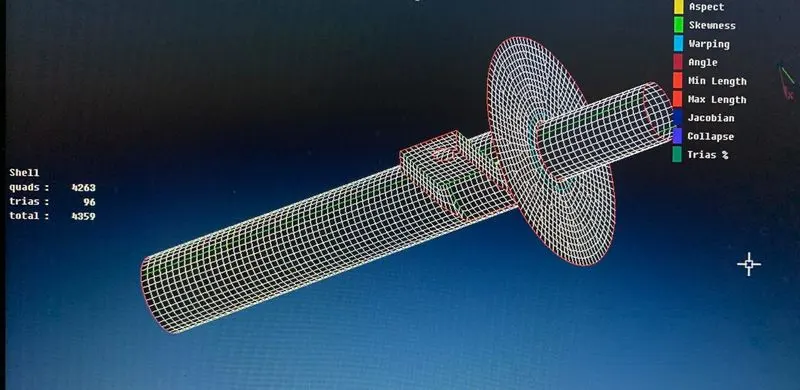
Fig: Parts with Uniform thickness after extracting MID and meshing
7. The parts having uniform thickness were asiigned PID (PSHELL)
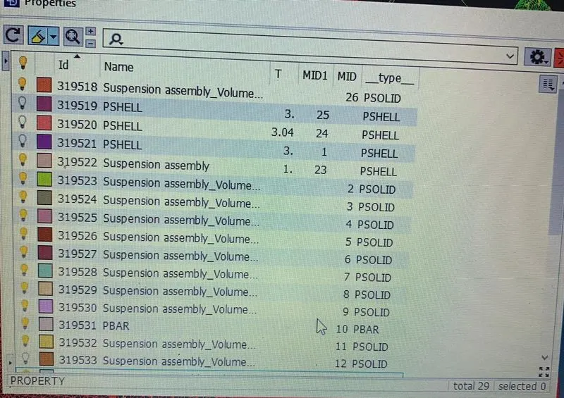
Fig: Assigned PID to the Meshed model with Uniform Thickness(PSHELL)
8. After this the parts with Non Uniform thickeness were meshed and Volume meshed.at the curved surfaces ortho tria pattern was used and Flat surfaces Tria mesh pattern was used
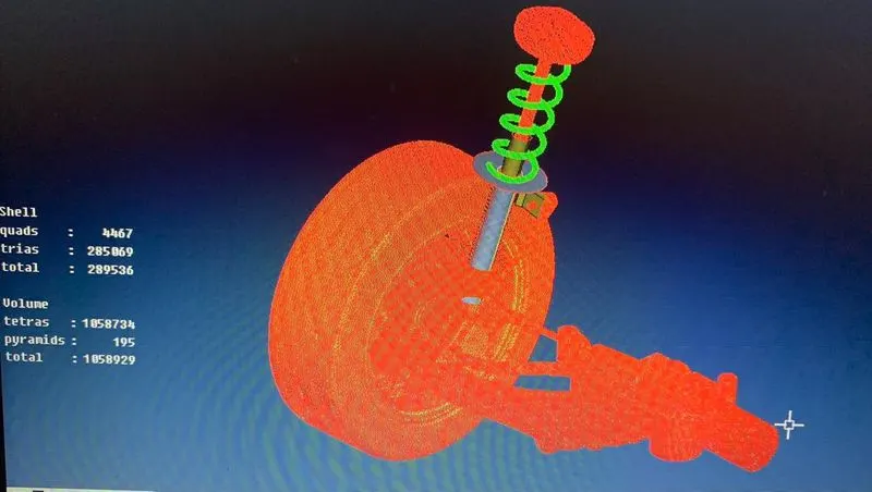
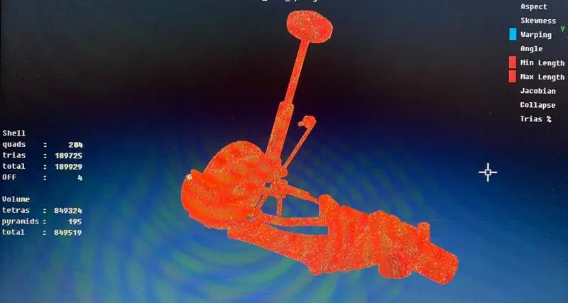
Fig: Supension assembly with Volume Mesh Fig:Parts with Non Uniform Thickness after Meshing
9. After meshing the Torsion spring was modeled using CBAR element.for modeling the Curves were used and modeling was done,which in turn resulted into below shown image .CBAR si considered as SSB during solving
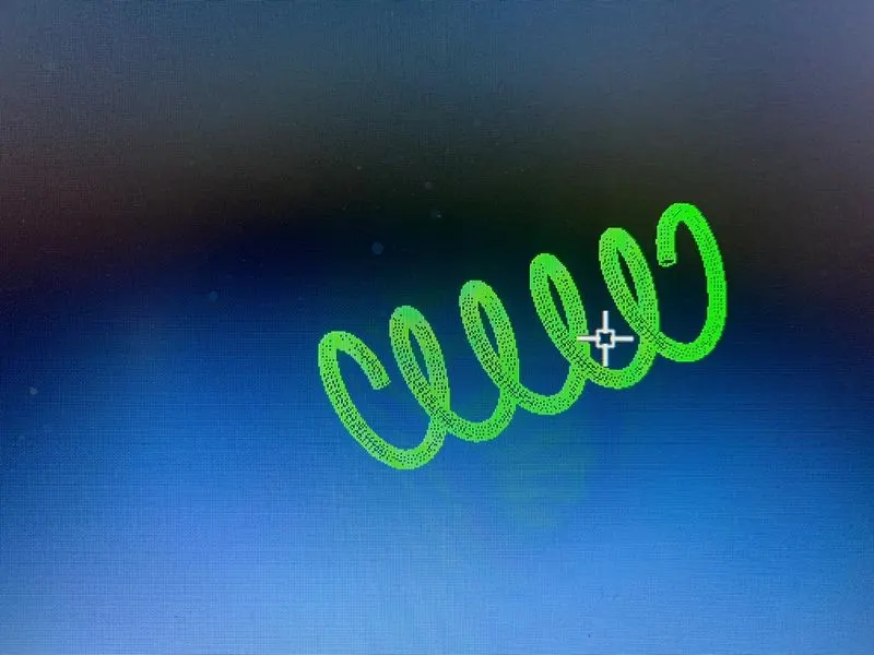
Fig : Spring element with CBAR
10. After this the whole model was checked for Quality criteria and meshing paramters the image of the whole model can be seen below
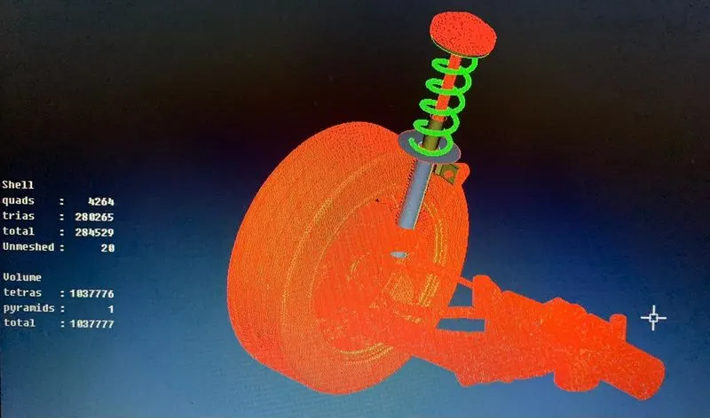
Fig: Meshed model of Rear Suspension system
Conclusion: Proper meshing method and Mid extraction method must be used for aceheiving above results. the parts with non uniform thickness must be volume meshed and Parts having uniform thickness must be meshed by exrtacting MID(Mixed elements).For any spring in NVH module CBAR should be used for modeling
Learning Outcomes: Came to know how to Mesh the parts with Uniform and Non Uniform thickness and how to design 1D elments (Spring)
The part was very complicated and after meshing such part gained a confident to mesh any part of auromobile in ANSA