Project - 2 - Meshing on the suspension Assembly
Project-2
For the given assembly, check for the geometrical errors and mesh with the given element Quality criteria. After meshing the component the thickness has to be assigned for mid surfaces. Use tetra elements to model non-uniform thickness components. Also use Appropriate connections to connect the component as suggested in the Project-2 video (Use PBAR elements to model suspension spring). At last perform Symmetry command to reflect the half finished model to the other side.
Common Note:
- Use Volume mesh for Tyre and Rim with below Quality criteria. (Use Tria Element)
- Use mid surface only when the thickness is uniform and less than 5 mm. (Use Mixed elements)
Quality Criteria for Surface Meshing of Tyre and Rim (Element type: Tria) :
|
S.No |
Quality Criteria |
Value |
|
1 |
Target/Average length |
6.5 |
|
2 |
Minimum Length |
5 |
|
3 |
Maximum Length |
10 |
|
4 |
Skewness |
45 |
Quality criteria for Surface Meshing of Non Uniform thickness components other than Tyre and Rim (Element type: Tria) :
|
S.No |
Quality Criteria |
Value |
|
1 |
Target/Average length |
4 |
|
2 |
Minimum Length |
2 |
|
3 |
Maximum Length |
6 |
|
4 |
Skewness |
45 |
Quality Criteria for Volume meshing of all Non Uniform thickness components (Element type: Tetra Elements):
|
S.No |
Quality Criteria |
Value |
|
1 |
Tet-collapse |
0.2 |
Quality criteria for Mid surfacing of Uniform thickness part which has thickness less than 5 mm (Element type: Mixed elements) :
|
S.No |
Quality Criteria |
Value |
|
1 |
Target/Average length |
4 |
|
2 |
Minimum Length |
2 |
|
3 |
Maximum Length |
6 |
|
4 |
Aspect |
3 |
|
5 |
Warpage |
15 |
|
6 |
Skewness |
45 |
|
7 |
Jacobian |
0.7 |
|
8 |
Minimum Quad Angle |
45 |
|
9 |
Maximum Quad Angle |
135 |
|
10 |
Minimum Tria Angle |
30 |
|
11 |
Maximum Tria Angle |
120 |
Steps in short: Geometry clean up-->Geometry check-->Surface Meshing for Volumetric mesh-->Volumetric mesh with Tetra Elements-->Perform Symmetry
PROCEDURES:
In TOPO
Geometry checking
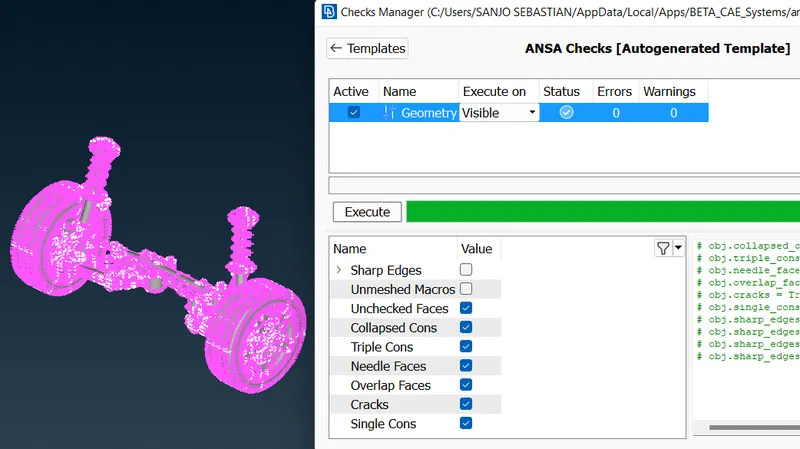
TOPO
After downloading the drawing Geometry, release cons and apply TOPO. Then go for a geometry check. Normally if cons are generated select all then clear it by Right click and fix. If not clearing tough fix manually. In this case after selecting all, go for right click and fix. All errors are cleaned and geometry is perfect. If not go for individual checks and cleaning.
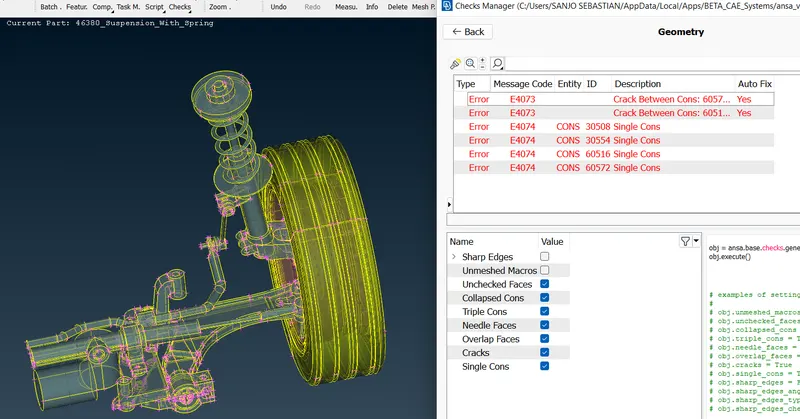
Geometry Checks and Fixing it
Single Cons(represented by red colour lines) - Edges which are shared with only one surface should be single cons. Single cons denote there is no connectivity between the surfaces in the model.
Double Cons(represented by yellow colour lines) -If any edge shared with two surfaces the that line is called Double Cons.
Triple Cons(represented by cyan colour lines) – if any edge is shared with three or more than three surfaces then that line is called triple cons.
Topology describes how elements are bounded and connected and Geometry describes the shape of each element.
2] Locking
The next part is locking the parent parts in order to take parent part alone.
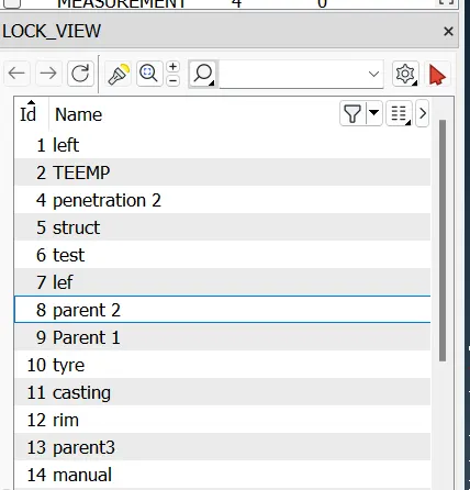
LOCK
3] Save
Save the settings, from tools- settings and save the file
- JACOBIAN--Is a measure of the deviation of a given element from an ideally shaped element. The Jacobian value ranges from -1.0 to 1.0, where 1.0 represents imperfectly shaped element.
- WARPAGE--Is defined as angle between normal to two planes formed by splitting the quad element along diagonals. max. angle out of the two possibilities is reported as warp.
- ASPECT RATIO
Is the ratio maximum edge length to the minimum edge length of an element. The ideal value of the aspect ratio is 1. However the aspect ratio of less than 5 is accepted.
- SKEWNESS
Is the angular measure of element quality with respect to the angles of ideal.
Assigning relevant PID
Set PID for all the regions separately
Use given quality criteria to mesh the component within the quality parameter
Assigning relevant quality parameter
The respective quality criteria were used to mesh each type of component
- tria quality on the surface mesh of solid components
- tria quality on the surface mesh for the Tyre and rim part
- mixed element quality on mid surface
as Tet- collapse - 0.2 was common quality criteria for tetra elements
MESHING
Casting is a fully automated process, Automatically mesh multiple model files without human interaction. Select the Casting tool to open the window. Give appropriate values. And Okay
- Auto generated FE by Casting Method.
- After Casting we can observe that some features are not have proper shape according to the parent component so, we have to check it and fix it Manually. First we have to set the base elements proper then go for features.
After corrections, go to Quality criteria > presentations parameters> select the check box shell as solid.
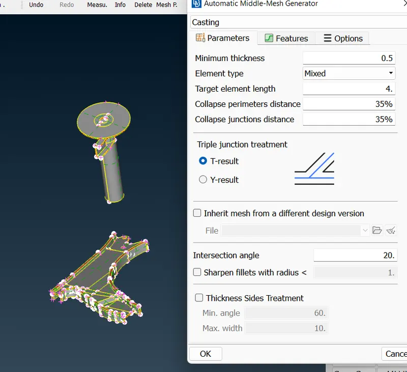
CASTING
VOLUME MESH
First we will mesh the complete surface of this model using trias elements. We will be using both normal tria will be used for capturing flat surface.
Mesh the complete surface area of the model with tria element such that quality criteria are fulfilled.
Now the next step is to define the model as volume so that volume mesh can be generated. For the current model, the volume is defined volume option in the volume mesh module.
After defining volumes, go to the list option under volumes in the volume mesh module the list options will show the list of defined volumes. We can now perform tetra mesh on the defined volume by right-clicking on volume and choosing either the tetra – rapid or tetra-FEM method. These are different algorithms used for unstructured in the case of solid component, first the surface was meshed according to given criteria and then the volume was defined using the define volume option in the V-mesh deck the volume were then meshed using tetra Rapid. Once volume mesh is done then release the mesh, it will be easy to separate the body and FEA- element for further process. Now we have to deploy appropriate connections between the components to assemble the suspensions model.
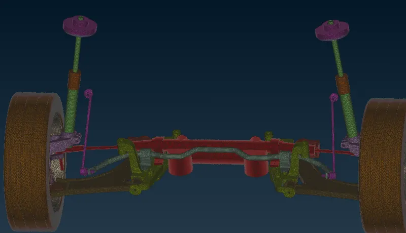
VOLUME MESH
Symmetry the other half Geometry:
the complete suspension assembly was generated using the mirror options under transform.
NASTRAN MODULE >ELEMENTS>RBE2>MANY NODES can be used to create a Custer element for bolt holes when there are no different properties defined to parts.
NASTRAN MODULE >ELEMENTS>RBE2>TWO NODES can be used to create a element to element connection if they are in different PIDs.
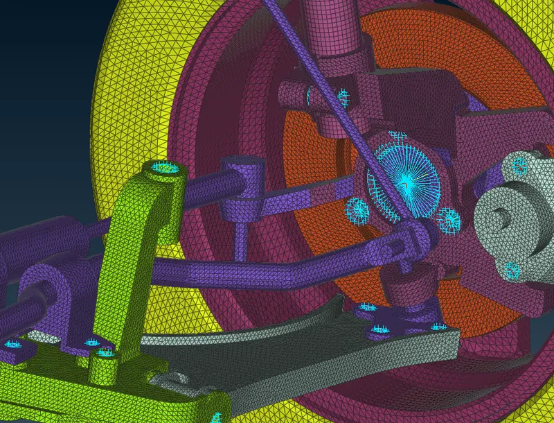
CONNECTIONS
CBAR
Generate a middle curve for the spring. By using the middle option in the curves. Connect the curve into a single curve. By using Connect. Create a COG point for the curve to define the orientation. Select the CBAR element. And give middle click. Give the element length as 3. Define area by giving radius by choosing shift key + ?. Assign radius and okay C bar will be created. Give tick in Line elements cross sections and check.
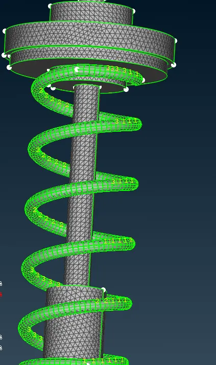
C BAR
LEARNING OUTCOMES
- Geometry cleanup and geometry check for provided CAD
- Thickness measurement at various parts and decide the type of the component
- Mid surfacing by using various techniques for sheet metal components
- Surface Meshing with provided Quality Criteria
- Defining volumes and doing Volumetric mesh
- Solving the failed elements by using Mesh improvement tools
- Use of Symmetry option
CONCLUSION
In this project, well connectivity has been established between the surfaces. The features have been captured properly. A good mesh flow have been achieved. Hence the Model has been reflected to the other side successfully. Hence the connection has been deployed in required regions. Hence Mid Surface and Shell Mesh has been performed for the bracket and lower spring insulator component successfully.
https://drive.google.com/file/d/1ZlgWUxIYg_TSJdga7eakP-qoEJpP_vnQ/view?usp=sharing