Week - 4 - 2D meshing for Plastic components
Project: 2D meshing for Plastic components
Model Taken: Bottle Cap
Aim:
For the given Plastic Bottle Cap model, check for the geometrical errors and take the mid surface by suitable mid surfacing techniques. PID and Thickness assignment has to be done for all the mid surfaces. Mesh the same with given element Quality criteria.
|
Si.No |
Quality Criteria |
Value |
|
1 |
Target/Average length |
1 |
|
2 |
Minimum Length |
0.5 |
|
3 |
Maximum Length |
3 |
|
4 |
Aspect |
3 |
|
5 |
Warpage |
15 |
|
6 |
Skewness |
45 |
|
7 |
Jacobian |
0.7 |
|
8 |
Minimum Quad Angle |
45 |
|
9 |
Maximum Quad Angle |
135 |
|
10 |
Minimum Tria Angle |
30 |
|
11 |
Maximum Tria Angle |
120 |
|
12 |
Tria Percentage |
15 |
STEPS TO FOLLOW :
Steps to follow in Short : Import Cad Geometry-->TOPO-->Geometry clean -up-->Midsurface generation-->Shell meshing-->Element Quality checks
PROCEDURES:
In TOPO
1] Geometry checking
After downloading the drawing Geometry, release cons and apply TOPO. Then go for a geometry check. Normally if cons are generated select all then clear it by Right click and fix. If not clearing tough fix manually. In this case after selecting all, go for right click and fix. All errors are cleaned and geometry is perfect. If not go for individual checks and cleaning.
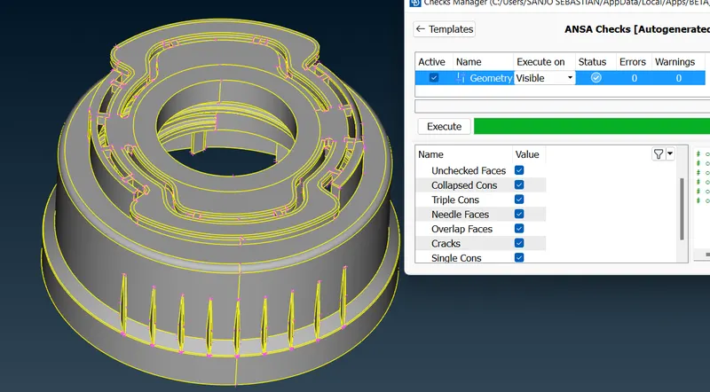
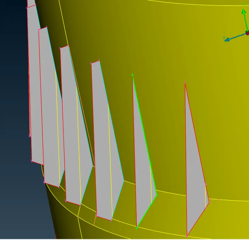
Single Cons(represented by red colour lines) - Edges which are shared with only one surface should be single cons. Single cons denote there is no connectivity between the surfaces in the model.
Double Cons(represented by yellow colour lines) -If any edge shared with two surfaces the that line is called Double Cons.
Triple Cons(represented by cyan colour lines) – if any edge is shared with three or more than three surfaces then that line is called triple cons.
Topology describes how elements are bounded and connected and Geometry describes the shape of each element.
2] Locking
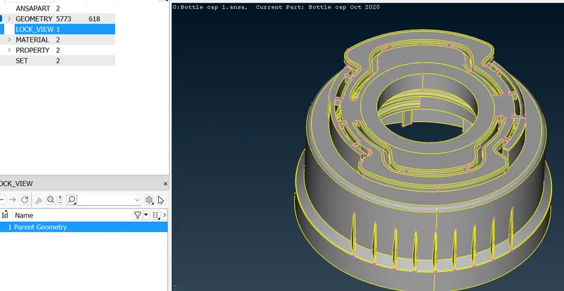
The next part is locking the parent parts in order to take parent part alone.
3] Save
Save the settings, from tools- settings and save the file
4] Orient
Apply orient on every mid surfaces, grey on top and yellow on bottom.
Go to module buttons-Faces-Orient-Select
5] Measurements
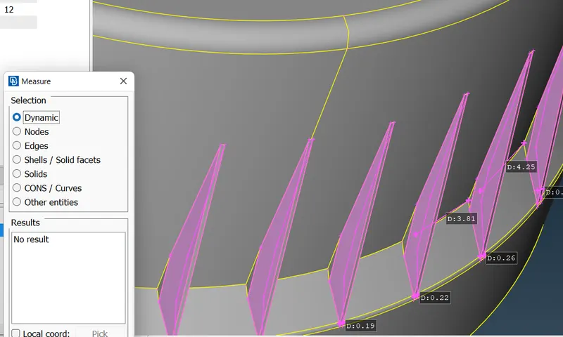
Apply measurements on every surface and store.
6] Offset / Middle method
Go to- Topo-Faces-Offset- then on the feature area- and make offset alone those parts which have uniform thickness.
Then separate it from parent part by i-not function.
Try not to delete parent part.
Due to this is a plastic component I have applied both the middle option and offset method.
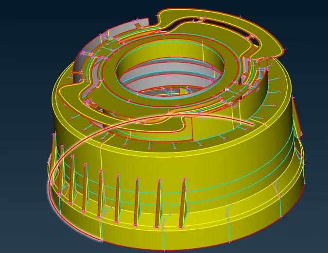
[Cleanup the mid surface for the meshing. Edit the cons and faces using cut, project cut, release, paste, orient and topo options to clean up the geometry for meshing]
In Mesh- Classic Mesh
7] Applying Perimeters
Go to- classic mesh- perimeters- select all-apply perimeters as 1.
Perimeters are the dots b/w two points on mesh on boundaries.
Go to- classic mesh- perimeters- select all-macros as 1.
Macros are the dots b/w two points on mesh on boundaries.
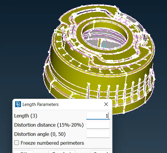
(Defeaturing- Is used to remove unnecessary surfaces radius, pin holes, edges. In short To neglect one criteria and doing adjustments in another.)
8] Measurement checkup
Check the measurements whether the surfaces are coming under our quality criteria, if not arrange the by using cut in macros.
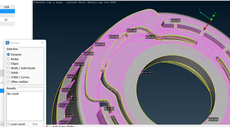
9] Counting the numbers
Go to perimeter- number to count the numbers and make it into even.
10] Mark and unmarking hotpoint
Points around feature areas are Marked after checking numbers else if after reconstruction shape or numbers may vary.
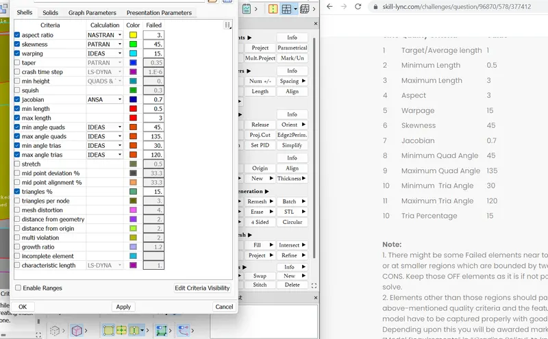
11] Quality Criteria
Apply the quality criteria given, by pressing 'F11'.
Go to- presentation prameters- put tick in elements
Enable range- apply - okay
Then save the settings.
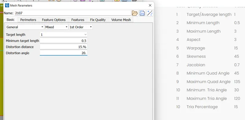
12] Mesh parameters
Go to-tools-utilities-mesh parameters
Type of mesh- general
Element Type- Mixed( It’s a mix of quad and tria elements)
Order of element- First order
Save the setting for future reference
13] Part ID
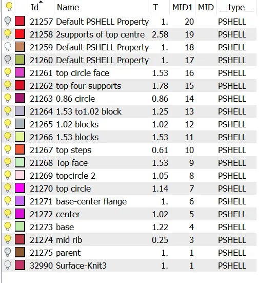
Create new properties and apply thickness
For using mesh we use 3 tabs mainly-1]Mesh Generation
-2]Shell Mesh
-3] Elements
14] Extend
To extend the surface.
15]Intersect
To intersect two surfaces.
16]Curves
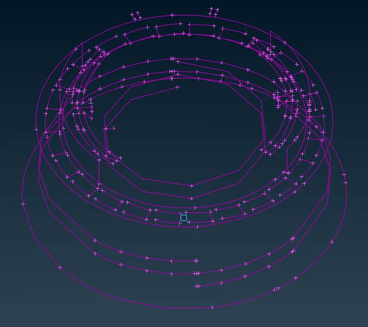
There is an enormous number of function for curves, used to make new surfaces, used to take mid planes, to get an rough boundary for lines, etc.
Here curves has an important role in making thread lines inside the sufaces.
17] Meshing
Apply Best mesh/ Free mesh to mesh the surfaces. Mesh the surface components independently.
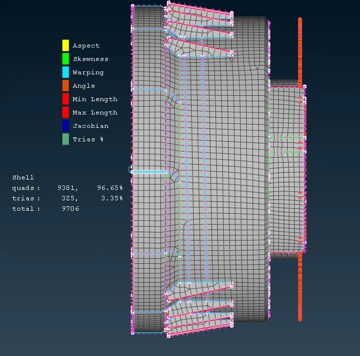
[In the hemming region(in the Outer panel’s bend region), Elements will fail for the Min length error due to the very small surface to capture the curved surface. In order to solve this Min length error, go for ‘defeaturing’ the mid surface. ]
18] Symmetry
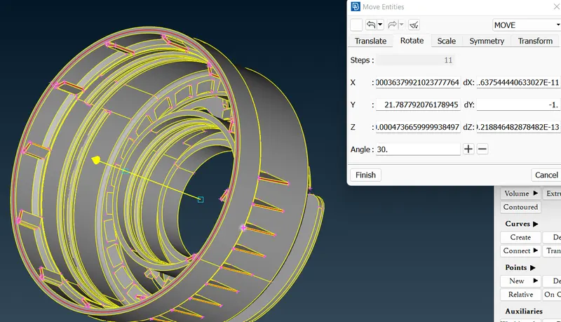
In this case ribs inside are in equal distance so we can apply symmetry for that we need to go for Points- On COG create centre points. Go to Transform- copy- Rotate by giving angle
19] Deleting hot points
By hot points- delete, for deleting unwanted nodes.
20] Split in elements
Used to delete unwanted trias and to generate a straight line by splitting the lines.
21] Swap
Used to delete unwanted trias and to redirect the line to another node.
22] Reconstruct
If the mesh flow is not perfect go for reconstructing the mesh and rerunning them will make perfect.
23] Smooth
If the mesh flow is not perfect and after split usage and lines are not keeping uniform distance go for smooth function in the mesh to make perfect line mesh.
24] Improve
Uses both smooth and reconstruction at same time.
25] Property ID
Create property id to assign thickness to the elements.
26] Join
Macros - Join to keep lines in mesh what we have drawn
27] Draw shell as solid
To find the mesh into solids by assigning thickness. Founds in Quality criteria - Presentation parameters
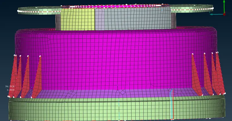
28] Release
Elements- Release to release all the drawings from geometry.
29] Save the file
LEARNING OUTCOMES
- The mesh should always look regular and proper.
- No two opposite trias came back to back, if came go for smooth option.
- By swap, tria's side can be moved or removed if unnecessary.
- The edges in ANSA are called cons and single cons are highlighted in red color, double in yellow color and triple in blue color. Double edge is shared by two surfaces and triple by three. Single cons are open edges.
- Aspect ratio is the ratio of maximum length to the minimum length
- Jacobian is a measure of deviation of a given element from an ideally shaped elements.
- Skewness is the Angular Measure of Element quality with respect to the Angles of Ideal Element Types.
- Maximum Angle out of the two possibilities is reported as "Warp Angle".
CONCLUSION
The given bottle cap model is meshed with given quality criteria using mid surface and assign various thickness among the surfaces.
The quality criteria was satisfied for the given quality parameters.