Project - 2 - Meshing on the suspension Assembly
AIM: To perform mesh and deploying appropriate connections to the suspension system of an Automobile.
Given suspension system:
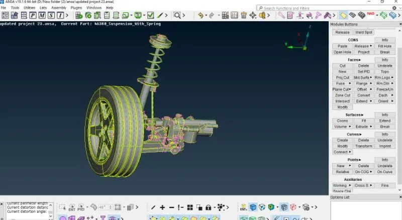
Fig1:
Quality criteria for different thickness components:
Quality Criteria for Surface Meshing of Tyre and Rim (Element type: Tria) :
|
S.No |
Quality Criteria |
Value |
|
1 |
Target/Average length |
6.5 |
|
2 |
Minimum Length |
5 |
|
3 |
Maximum Length |
10 |
|
4 |
Skewness |
45 |
Quality criteria for Surface Meshing of Non Uniform thickness components other than Tyre and Rim (Element type: Tria) :
|
S.No |
Quality Criteria |
Value |
|
1 |
Target/Average length |
4 |
|
2 |
Minimum Length |
2 |
|
3 |
Maximum Length |
6 |
|
4 |
Skewness |
45 |
Quality Criteria for Volume meshing of all Non Uniform thickness components (Element type: Tetra Elements):
|
S.No |
Quality Criteria |
Value |
|
1 |
Tet-collapse |
0.2 |
Quality criteria for Mid surfacing of Uniform thickness part which has thickness less than 5 mm (Element type: Mixed elements) :
|
S.No |
Quality Criteria |
Value |
|
1 |
Target/Average length |
4 |
|
2 |
Minimum Length |
2 |
|
3 |
Maximum Length |
6 |
|
4 |
Aspect |
3 |
|
5 |
Warpage |
15 |
|
6 |
Skewness |
45 |
|
7 |
Jacobian |
0.7 |
|
8 |
Minimum Quad Angle |
45 |
|
9 |
Maximum Quad Angle |
135 |
|
10 |
Minimum Tria Angle |
30 |
|
11 |
Maximum Tria Angle |
120 |
Note: Quality criteria for Mid surfacing of Uniform thickness part which has thickness less than 5 mm (Element type: Mixed elements) :
There are various steps before going to the meshing procedure:
- Import the CAD model
- Geometry cleanup
- Mid surface extraction and assign the thickness, PID
- Meshing process
IMPORT THE CAD MODEL:
- First Import the CAD model from the files to ANSA software and go to the mesh mode there we can set the length(1mm) for perimeters as well as macros for to perform all operations properly and good visibility of model.
- After that do the topo to the entire model and check material Id is assigned to all property IDs and make sure that material ID should be defined as ticked in the dialogue box as shown in the below fig. If we are not defined the material, ANSA will not consider component as material.
Fig2: Imported CAD model.
GEOMETRY CLEANUP:
- We can check the geometry using the check geometry under the toolbar when we click on it it will show the errors like unchecked faces, needle faces, shraps edges,triplecons, single cons etc. we can remove the all those errors by using the Auto fix option. All errors cannot fix by the auto-fix option there are some errors like triple cons we can go area by area and remove them manually. After removing those we can again execute the check geometry until it shows execute 100%.
- If the Auto cleanup is not able to fix the issues then we have to manually work on it to fix the issues for that we have to split the model into parts then we have to fix that issues for our convinence.
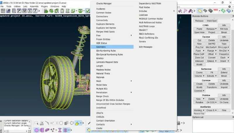
Fig3: Performing the geometry cleanup
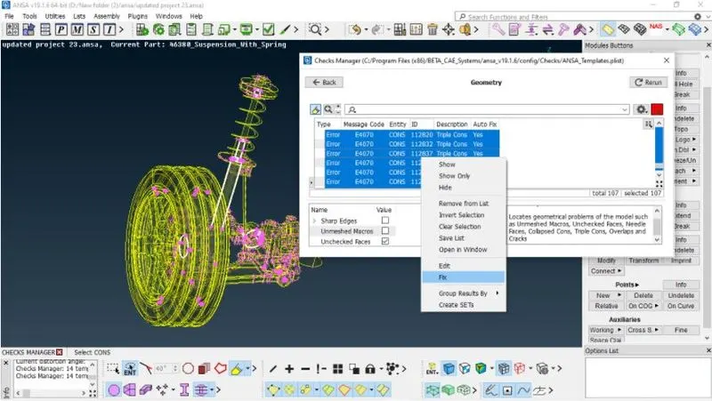
Fig4: Using the autofix option to eleminate the errors
- After performing Topo there is a some surface distorsion errors we have to fix it either manually or Autofix option.
- We can check the geometry using the check geometry under the toolbar when we click on it it will show the errors like unchecked faces, needle faces, shraps edges,triplecons, single cons etc.
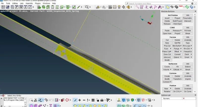
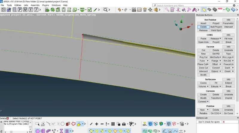
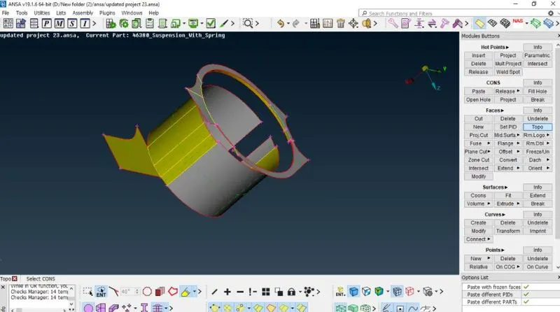
Fig5: These are the errors we have fix it manually.
- Still some errors are there we have to fix it manullay.
- If there is any uncheked face is there we have to fix it maunally by releasing the hot points.
- It will occur because of the irregular geometry and constarined hot points.
- If there is any uncheked face is there then we have to select delete that hotpoint or face creating the new surface is the best way to avoid such things.
- All errors cannot fix by the auto-fix option there are some errors like triple cons we can go area by area and remove them manually. After removing those we can again execute the check geometry until it shows execute 100%.
MIDSURFACE EXTRACTION:
As we know that with given request Mid surfacing is done for Uniform thickness part which has thickness less than 5 mm.
- We should extract the midsurface for the whole component, first go through the individual component and measure the thickness to extract the midsurface.
- Go to offset option under faces and make sure click on the feature angle to select the entire component then give the offset value then midsurface occurs in the middle of your parent body.
- We can create the new property IDs for each component by using the set PID option it will ask shell card click on that and define the thickness.
- There are many ways to extract the midsurface like offset,faces middle and curves middle for complex geometry.
Midsurface for Uniform thickness part :
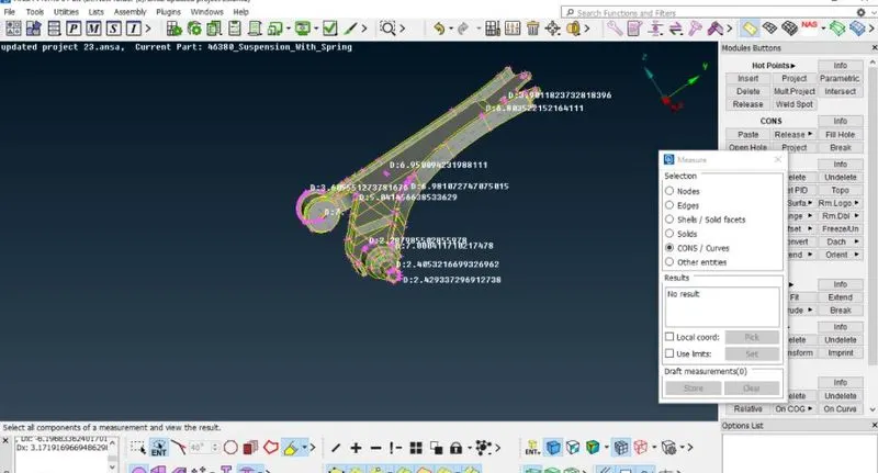
Fig6: Part having different thickness
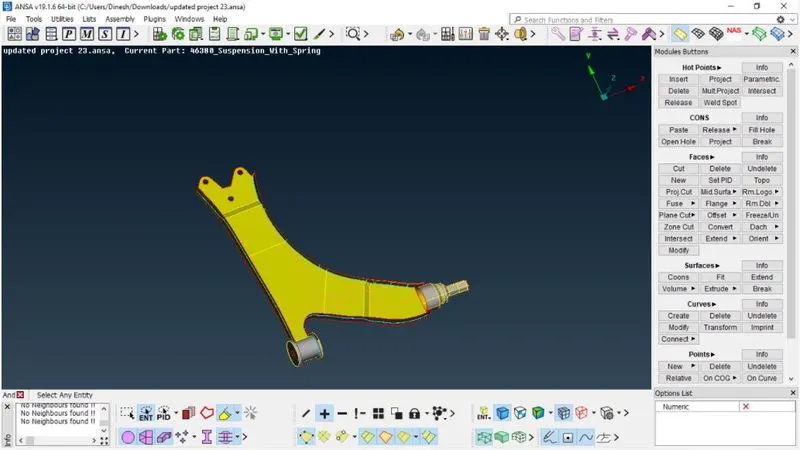
Fig7: Exracted the mid surface
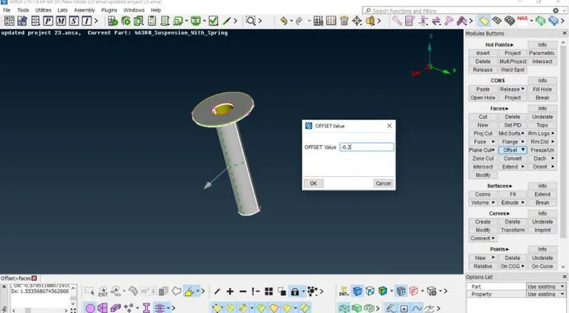
Fig8: Struct rod
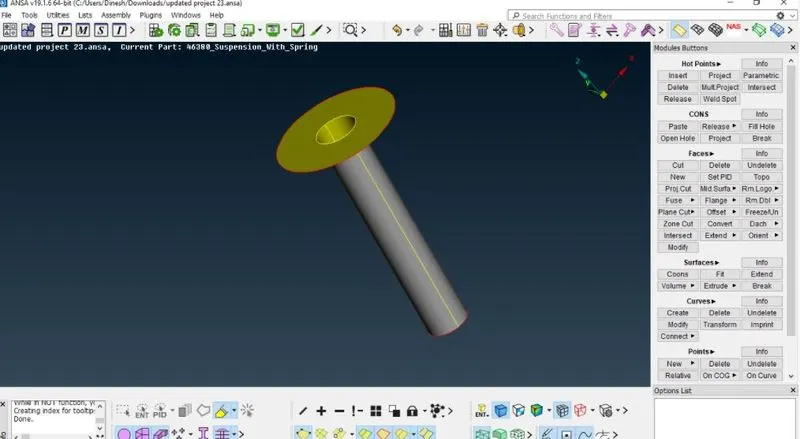
Fig9: Midsurface of Struct rod
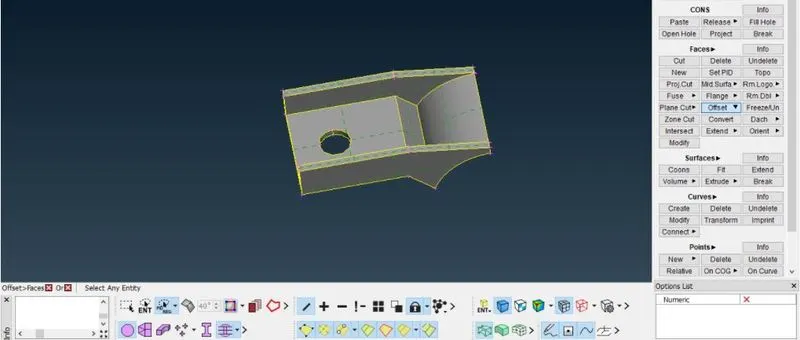
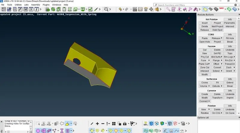
Fig10: Pillow hinge
Defeaturing:
Defeaturing is the removal of details in the geometry in order to make the shape of the part simpler. Surface fillet, Pinholes, Edge fillets or we have to compromise on the one feature to save another feature.
- The fillet which will be less than minimum length should be defeatured.
- There two different ways to deafeature one is datch option and other is divide faces.
- datch will be delete the fillet from the sharp edge.
- Divide face will capture the fillet without any geometry distortaion.
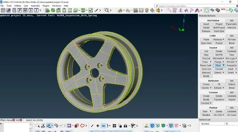
Fig11:Before deafeaturing
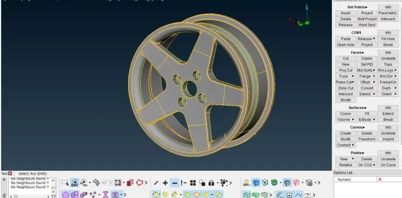
Fig12:After deafeaturing
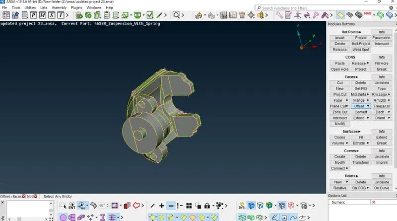
Fig13:Before deafeaturing
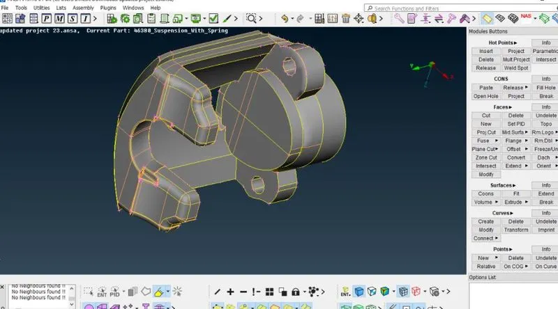
Fig14: After deafeaturing
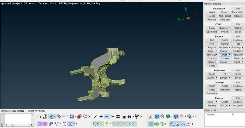
Fig15:Before deafeaturing
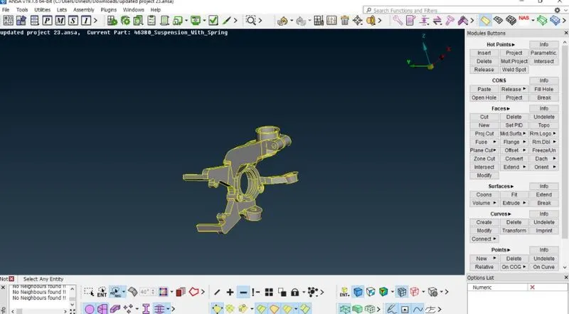
Fig16:After deafeaturing
Meshing:
A mesh is a network that is formed of cells and points it can have almost any shape of any size and is used to solve partial differential equations. each cell of the mesh represents an individual solution of the equation when combined with foe whole network results in a solution for the entire mesh.
- Before going into the meshing we have to set the quality criteria parameters and Mesh parameters.
- In presentation parameters enable the tick to the % of elements and put the details of demand effect to all details.
- In mesh parameters we should give the target element length, min length and max length as shown below images.
- In 2D meshing for midsurface we are going with mixed mesh flow with both quads and trais as per the given Quality criteria.
Quality criteria for 2D meshing with uniform thickness:
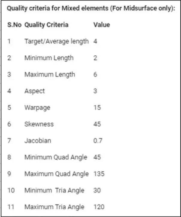 .
.
Shell Meshing: we have to give the perimeter length and macro length.Mesh module>perimeter length>macros>enter the value.
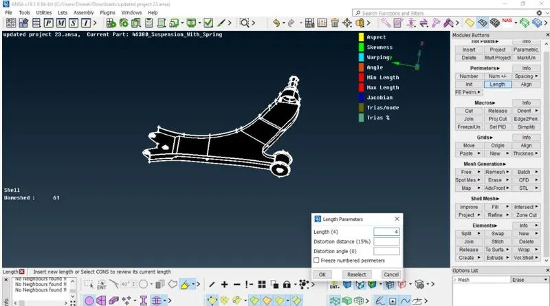
Fig17: Before meshing
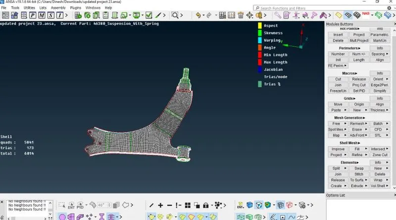
Fig18: After meshing
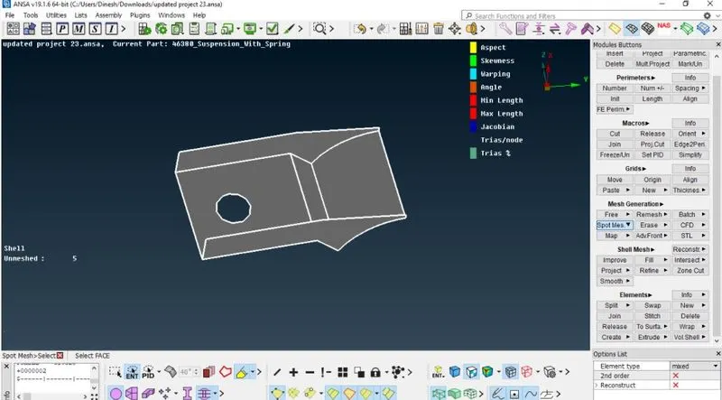
Fig19: Meshing the part
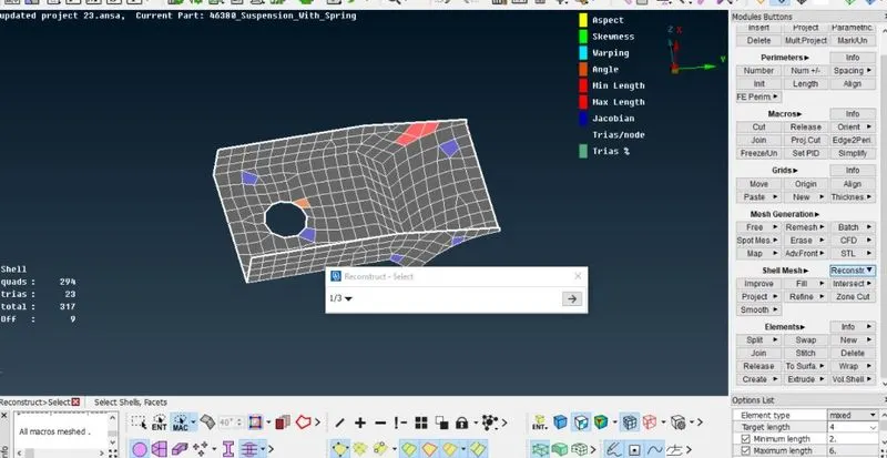
Fig20: As we shown in above there is quality errors to clear that errors we have to reconstruction option.
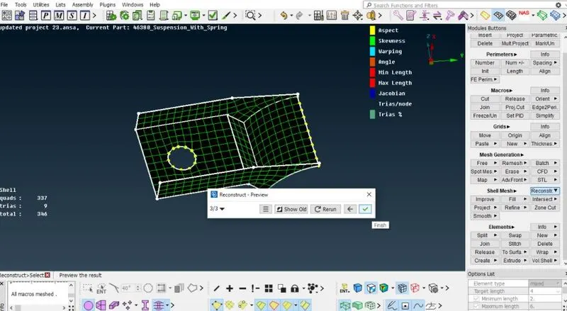
Fig21: Reconstruction done & there is no quality errors as we see in aboive image.
- We have to use split, swap, paste, reconstruction, options to adjust the trais in a perfect way.
- Reconstruction is done by using the reconstruction option and smooth will reduce failing the elements.
Volume Meshing:
- Before performing the volume mesh we have to do the shell mesh on the surface of the components.
- Here we are using the two types of trais ortho trias and normal trias
- Ortho trias are used on the curved surface and normal trias are used on the flat surface.
- Otho trias will capture the fillets and holes without any kinks and raised edges.
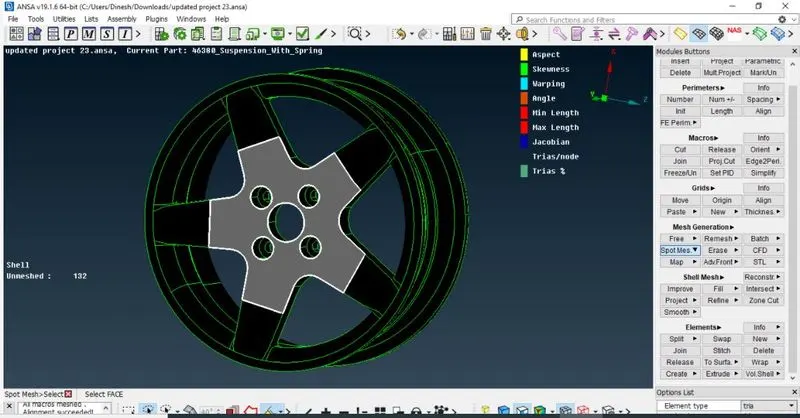
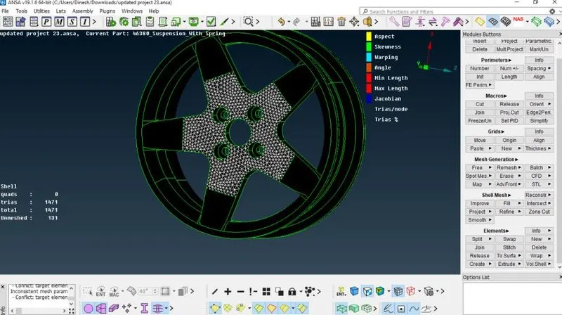
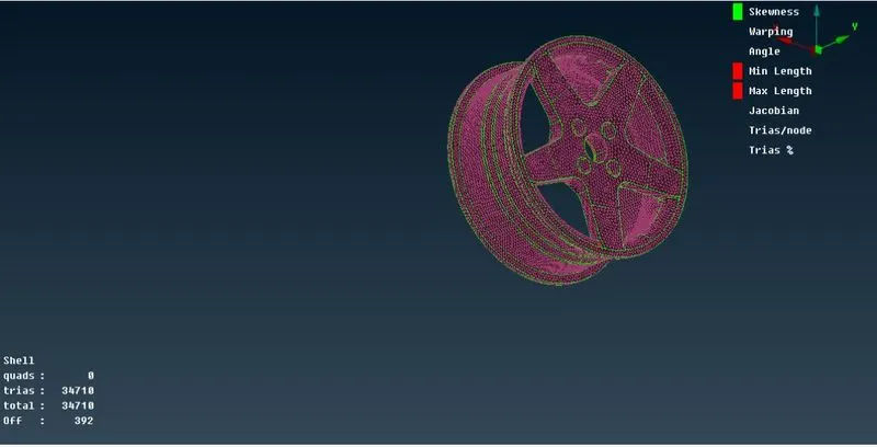
Fig22: Shell mesh completed on the entire surface as shown in above.
- To perform the volume mesh we have to define it and add it to the list.
- Then we can move to the list right click then it will ask the mesh to Tetra rapid or Tetra FEM.
- After meshing we have to check the quality if any any element is failing for the tet collapse.
- Then We have to manually clear the tet collapse.
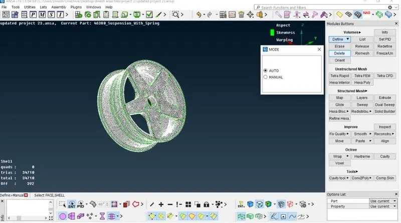
Fig23:Defining the volume
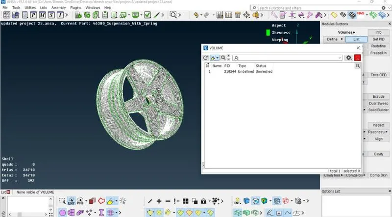
Fig24: Adding volume to the list as shown in above.
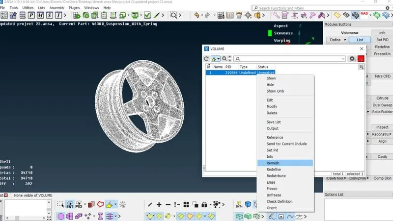
Fig25: Selecting the remesh option to mesh the volume.
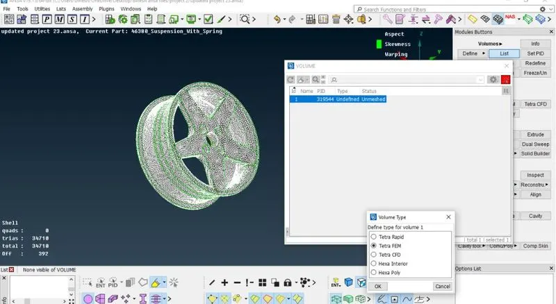
Fig26: Selecting the different algorithms of mesh as we know.
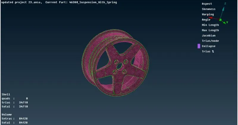
Fig27: Volume mesh is generated.
Simillarly Other Parts :
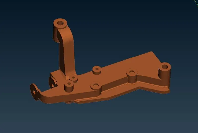
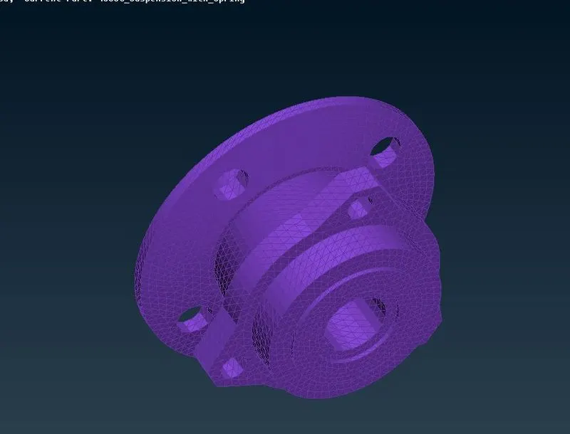
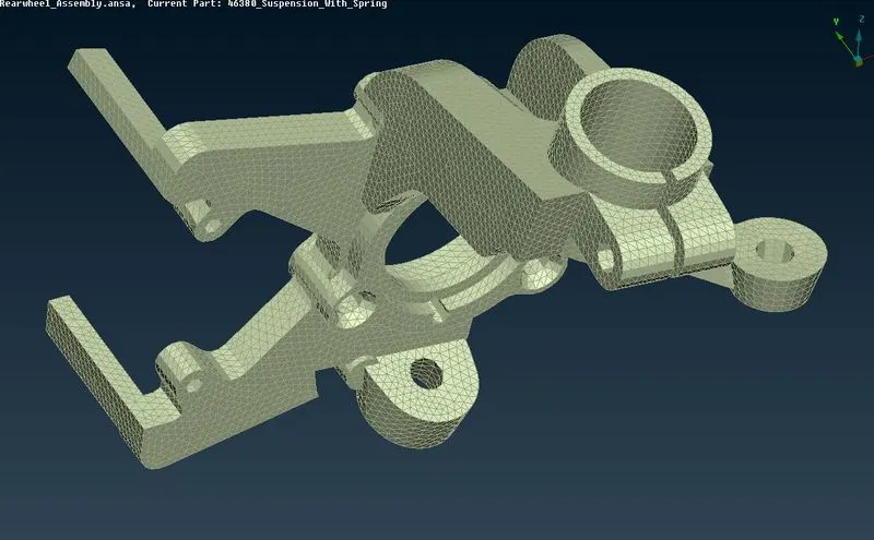
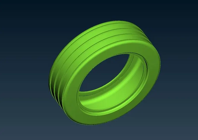
Fig30:
VOlume Mesh for entire system:
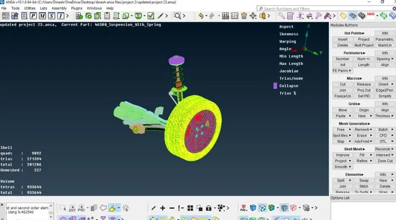
Fig31:
Connections:
Here connections are used to connect the two or more parts together at subsystems level. these connections are done before doing the Analysis on the component level. these connections are used for the constraint of the required regions.
there different types of connections
*Cluster or Many node RBE2: These are used to represent the nut and bolt connection in the subsystem level and if we have washer we can use the zone cut options to constrain the region of the washer.
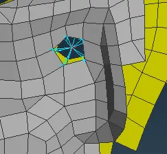
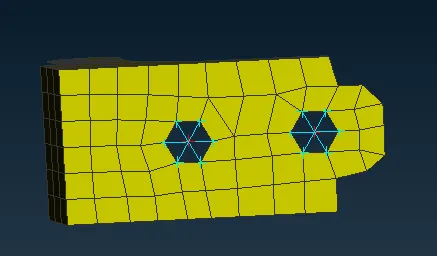
Fig32:
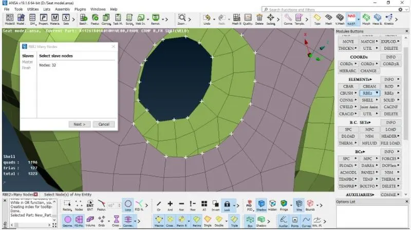
Fig33: Selecting the nodes of two components.
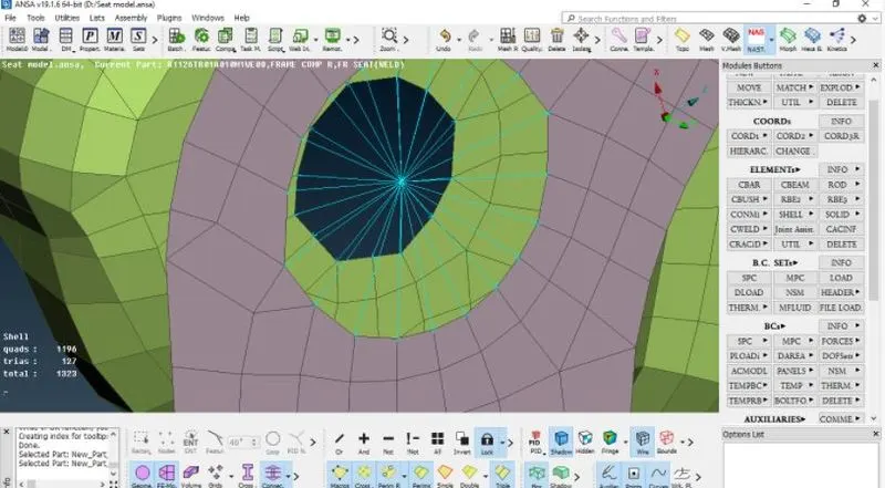
Fig33: Obtained the cluster RBE2 connection.
Two nodes RBE2: These connections are used to represent the rotatory motion of the region, this two-node RBE2 are connected between two many node RBE2 connections.
as shown below. here we can constrain region where we can require.
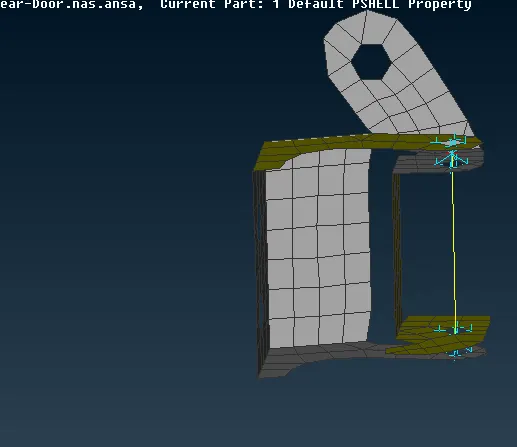
Fig34:
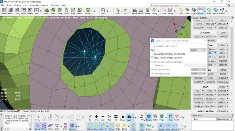
Fig35:Indi vidual nodes are selected
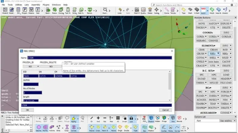
Fig36: Creating the PID
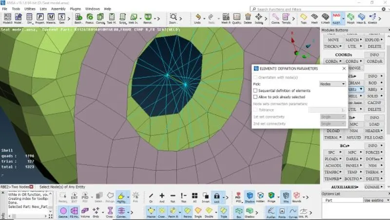
Fig37: Two node RBE2 obatined.
Welding: welding also one type of connections used to connect the parts in the component these welding also be defined before going in to the Analysis.
There are different types of welding we used here as per our requirement:
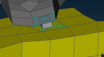
*Spot welding: It will define the weld between two parts as shown the below.
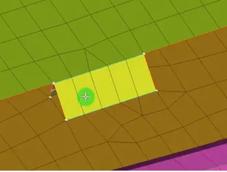
*Overlap shell welding: It is used when two surfaces are parallel to each other
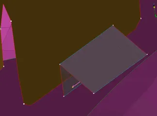
*Y-joint shell welding: It is used when two surfaces are parallel to each other
Procedure:
- We need to create a curve by using a feature2 curve in the mesh module if is an Fe element.
- Then after we need to convert the curve into the the seam line.
- Then by using connectiom we should slect the line and we need to select the components to be welded by pressing F1 and then select overlap shell/y jiont shell.
- Mention the search distance and we need to mention width and step length as target element length and create a weld PID by pressing shift+? and apply.
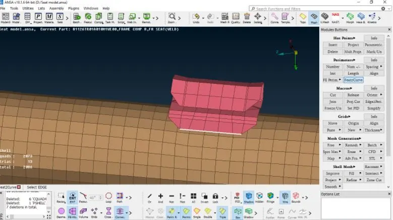
Fig38: Creating the curve
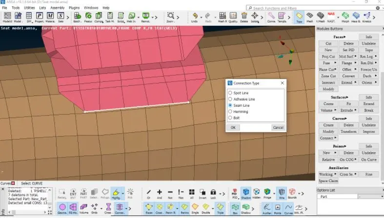
Fig39: Converting into the seam line
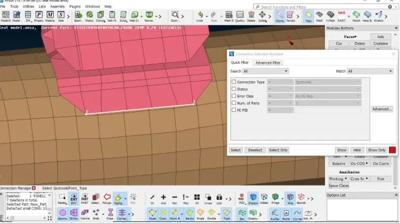
Fig40: Selecting the type of weld
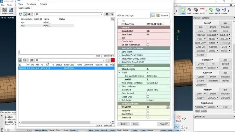
Fig41: Defing the two components
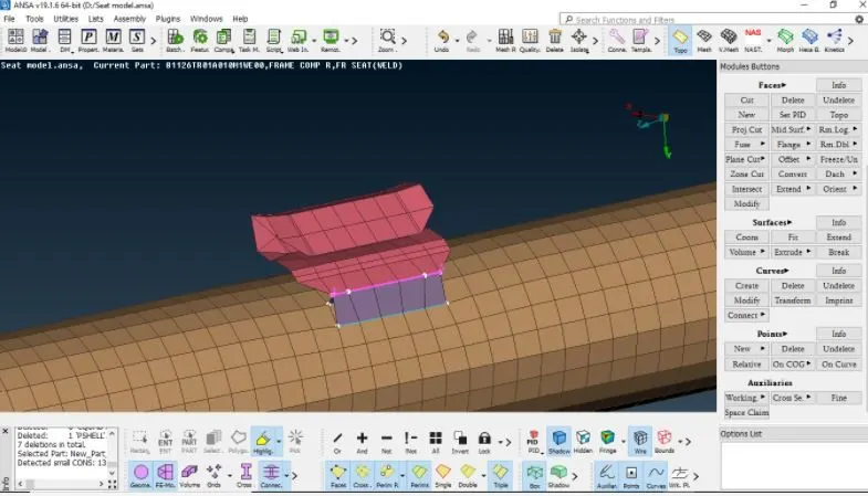
Fig42: Weld is deployed.
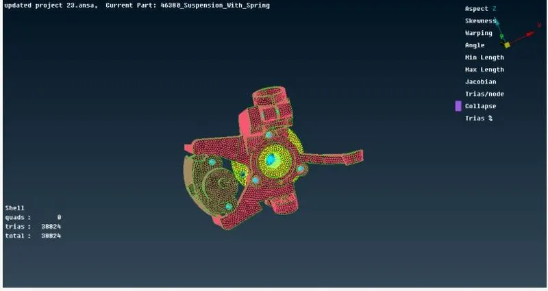
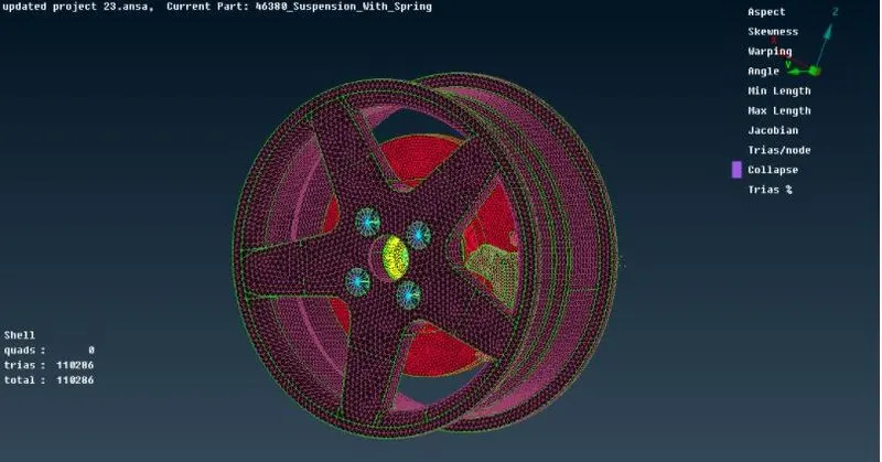
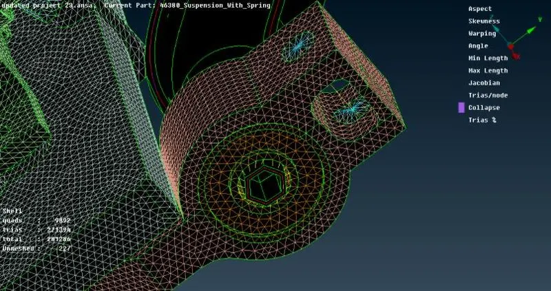
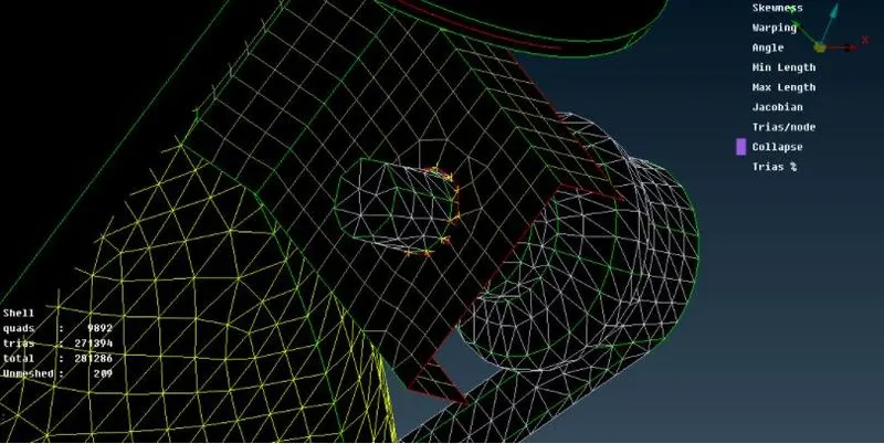
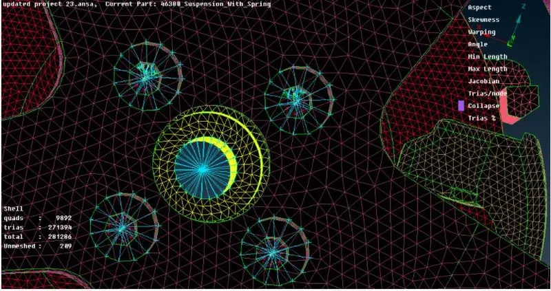
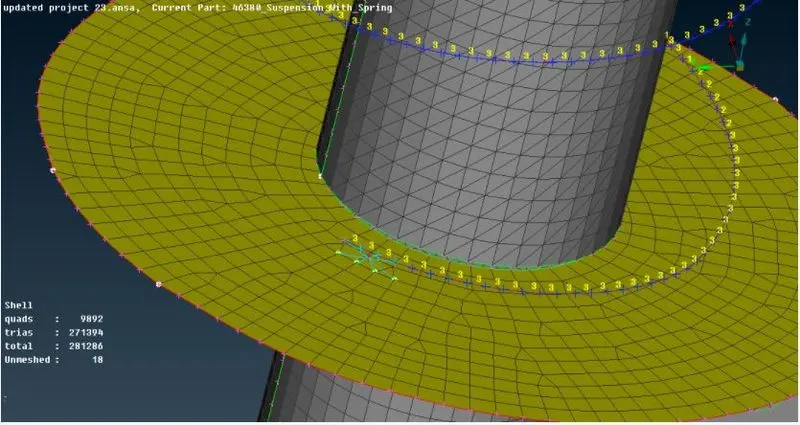
Entire Suspention system After Reflection:
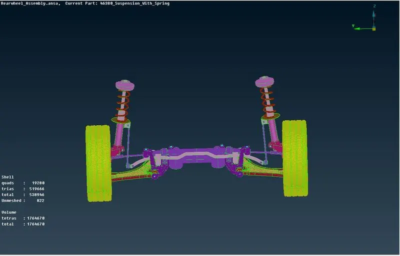
CONCLUSION: The given suspension model checked for the geometrical issues and meshed with both 2D mixed elements,when thickness is higher than the 5mm we meshed with tetrahedral mesh with given quality criteria with no Tet collapse.
Learning Outcomes:
- I am able to understand how to obtain better mesh flow over some critical areas on fillets and also eliminating the trias by using the split, swap, rebuild options.
- In this I am able to understand the doing the midsurface of a component using both auto midsurfacing and manual midsurfacing with options midsurface and offset.
- Understood how to reduce the quality of errors in mesh.
- Understood the feature capturing of the fillet areas as well as complex geometry.
- I understand how to generate the volume mesh or tetrahedral mesh in this challenge.
- I learned where we should use the normal trias and ortho trias.
- Different types of mesh Tetra rapid and Tetra FEM.
- How to fix the Tet collapse issues in the model.