Project - 2 - Meshing on the suspension Assembly
Aim:
To check for the geometrical errors and mesh with the given element Quality criteria. After meshing the component the thickness has to be assigned for mid surfaces. Tetra elements to be used to model non-uniform thickness components. Also appropriate connections to connect the component as suggested in the Project-2 video (CBAR elements to model suspension spring to be used). At last Symmetry command to reflect the half finished model to the other side to be used.
Procedure:
Importing CAD model and geometrical error check:
1. Import the CAD geometry in ANSA. The faces of the geometry are properly stitched and oriented properly.
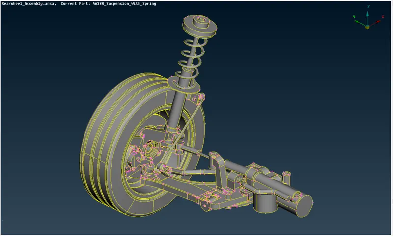
Figure 1 - Imported geometry of IP console model
2. Using Tools --> Checks --> Geometry, the geometry of the model are checked for errors in geometry
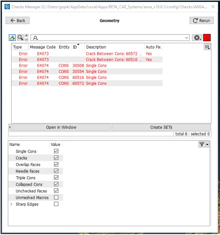
Figure 2 - Checking for errors in geometry
3. Select all the errors, right click and select “Fix” for fixing the errors automatically.
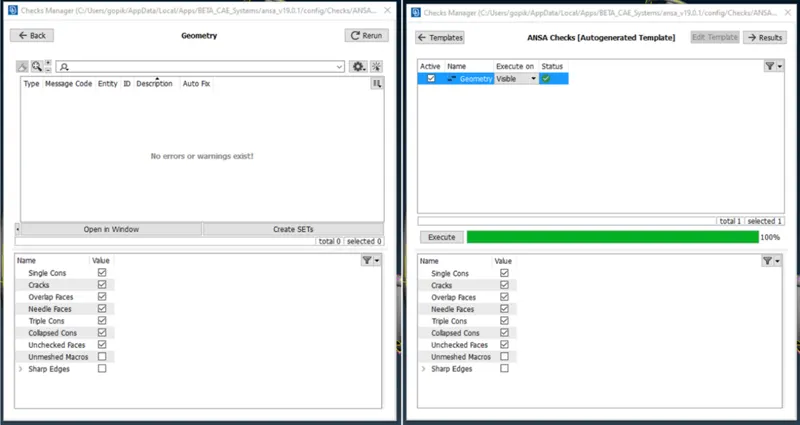
Figure 3 - Automatic Fixing of geometrical errors
4. The given mesh parameters have been assigned to the models as follows:
a) The tyre and rim are assigned with the following mesh and quality criteria parameters:
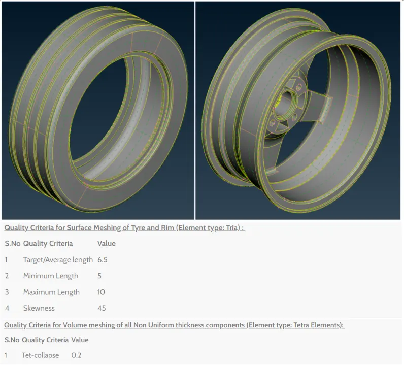
b) The following components were considered for solid meshing with tria elements and the mesh and quality criteria parameters are as follows:
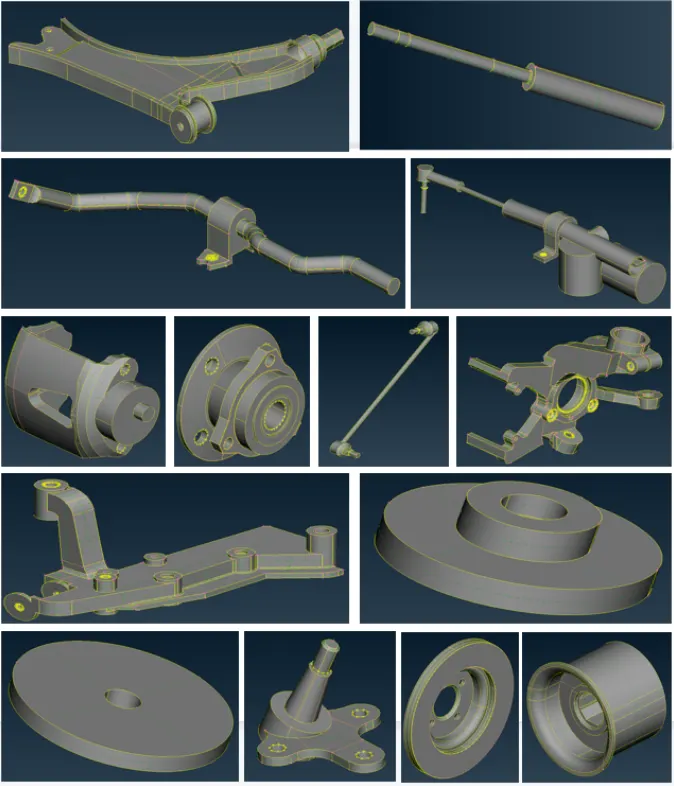
Figure 4 - Parts meshed with solid elements
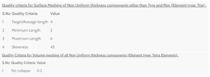
Figure 5 - Mesh and quality criteria for solid meshing
c) The following components with thickness less than 5 mm were meshed with below mesh parameters and quality criteria:
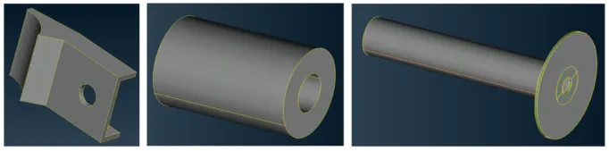
Figure 6 - Parts with uniform thickness
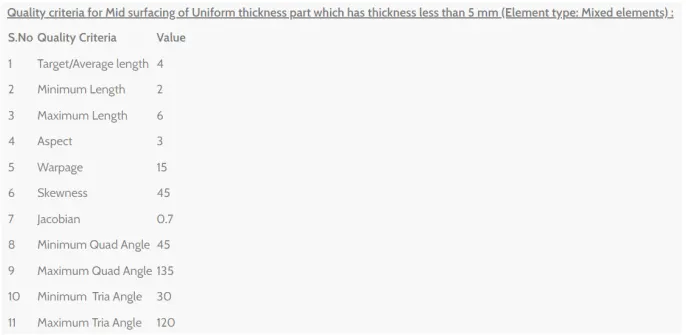
Figure 7 - Mesh and quality criteria parameters for mid surface meshing
5. The given “Mesh parameters” and “Quality criteria” are entered and are saved as .mpar and .ansa_qual.
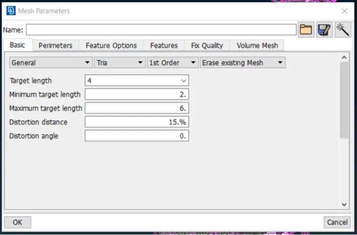
Figure 8 - Mesh parameters
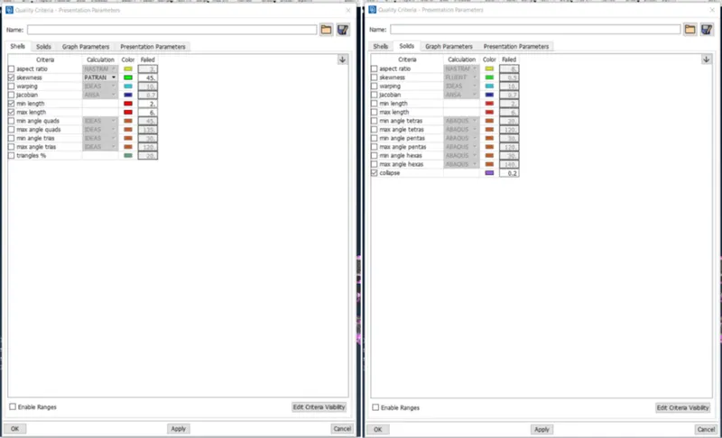
Figure 9 - Quality criteria
6. Separate PSHELL entities with separate PIDs are created for each part in the suspension assembly is created.
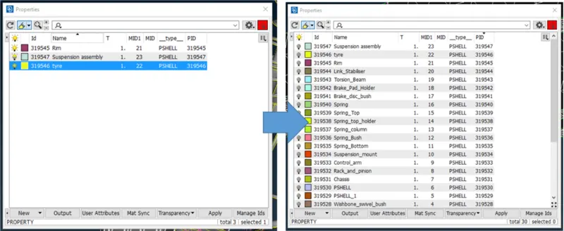
Figure 10 - Create separate PIDs
Mesh generation:
Solid Meshing of non-uniform thickness components:
The initial defeaturing and meshing of the model is done using Batch mesh manager and is done as follows:
1. In the Batch mesh manager, a new Meshing scenario is created
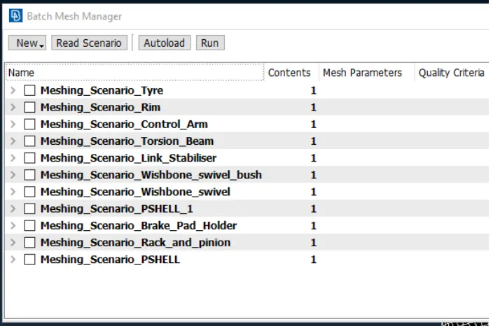
Figure 11 - Create Meshing scenario
2. Then, Right click on the meshing scenario --> Edit --> Contents. Then the mid surface part is assigned in the meshing scenario as shown below:
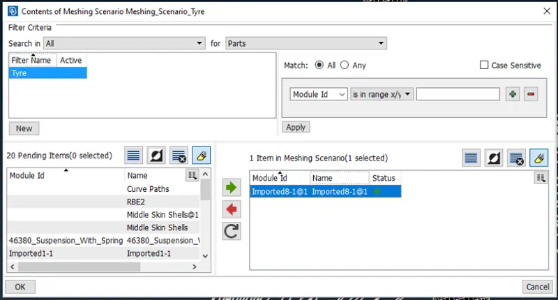
Figure 12 - Assign Contents in Meshing scenario
3. Then, the mesh parameters and quality criteria are checked and the option Run is clicked. Once complete, the status is shown as “Completed”
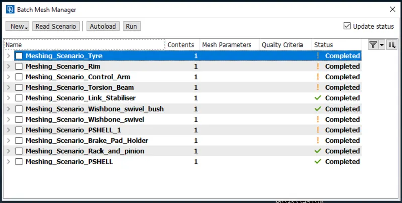
Figure 13 - Batch mesh manager after completion
4. The completed surface mesh after batch meshing is as follows:
a) Tyre & Rim:
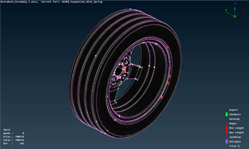
Figure 14 - Mesh generated using batch mesh manager
- The mesh created using batch mesh still had many OFF elements and also unmeshed elements.
- The elements that failed to generate from batch mesh and the elements that are found to be improved are corrected by using one of the below possibilities:
- Mesh Generation --> Erase --> Select - to erase mesh in an area
- Mesh Generation --> Free / Spot Mesh --> Select --> to remesh the area
- Shell Mesh --> Reconstruct- to rearrange the mesh.
- Shell Mesh --> Smooth - to smoothen the mesh and arrange it equally
- Elements --> Swap - to rearrange the tria elements and hence better mesh flow
- Mesh --> Macros --> Cut or Topo --> Faces --> Cut - to create feature lines using left click and remove feature lines using right click
- Evenafter rearranging the mesh, still there are some OFF elements present that fail due to minimum length quality criteria
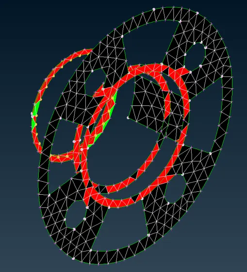
Figure 15 - OFF elements in tyre and rim
b) Other parts:
- The other parts meshed after batch and correction are as follows:
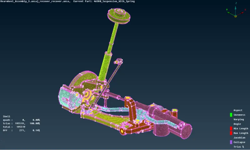
Figure 16 - Parts with solid mesh
- These parts also have OFF elements of 271 Nos.
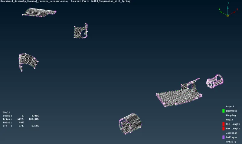
Figure 17 - OFF elements in solid meshing
Volume mesh generation:
Below steps were repeated for each part for volume definition
- In V.Mesh tab, Volumes --> Define --> Manual --> Auto is selected
- Each part in PSHELL is selected and volume is defined as shown below:
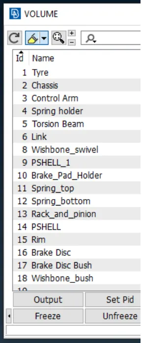
Figure 18 - Volume definition
- All the created volumes in the list are selected.
- By selecting right click --> Remesh --> Tetra Rapid, the volume mesh is created
- The collapsed elements are fixed using move option
- The model with volume mesh generated is as follows:
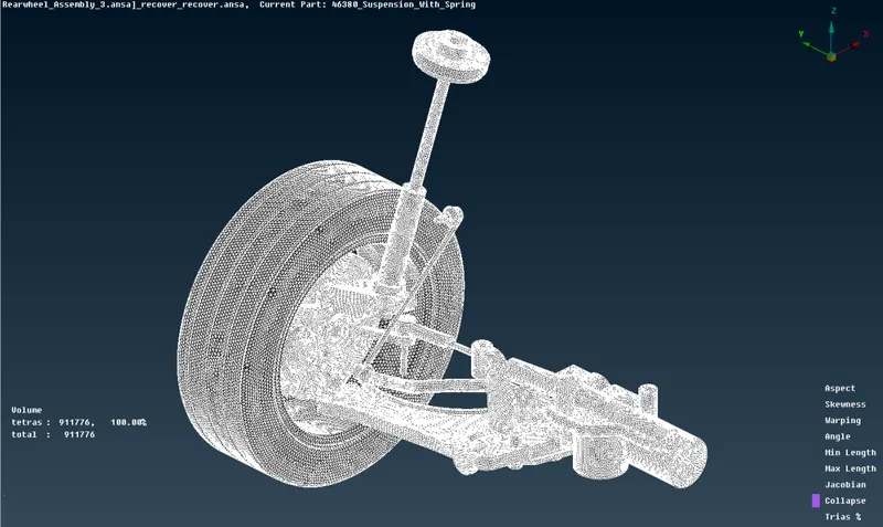
Figure 19 - Volume meshed model
Midsurface meshing of uniform thickness components:
- The midsurface mesh for the suspension mount was created using Topo --> Mid Surface --> Casting. The created mid surface mesh is as follows:
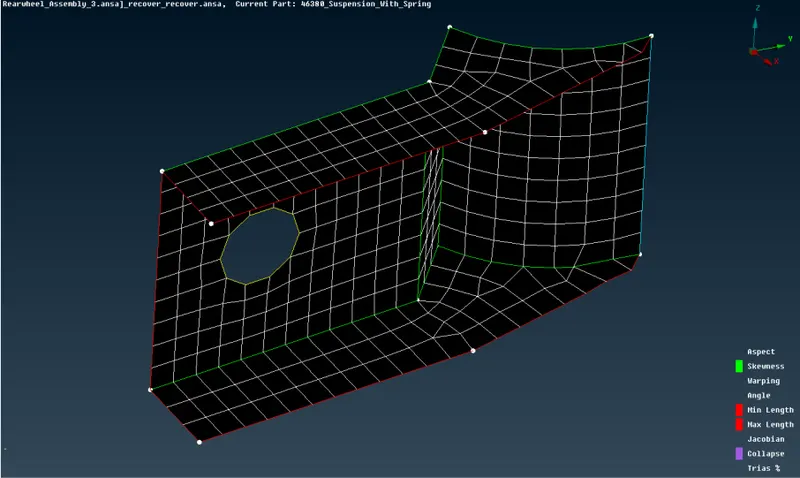
Figure 20 - Mid Surface meshing of suspension mount
- Proper thickness of 3mm is assigned to the PID card which is created automatically after mid surface creation
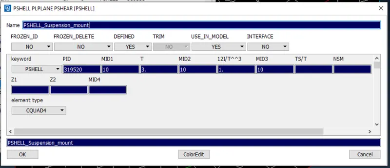
Figure 21 - Assign Thickness
- The other two parts for mid surface meshing are created using Topo --> Faces --> Offset Meshing was done by using Free / Spot mesh algorithms and mesh reconstruction as discussed previously.
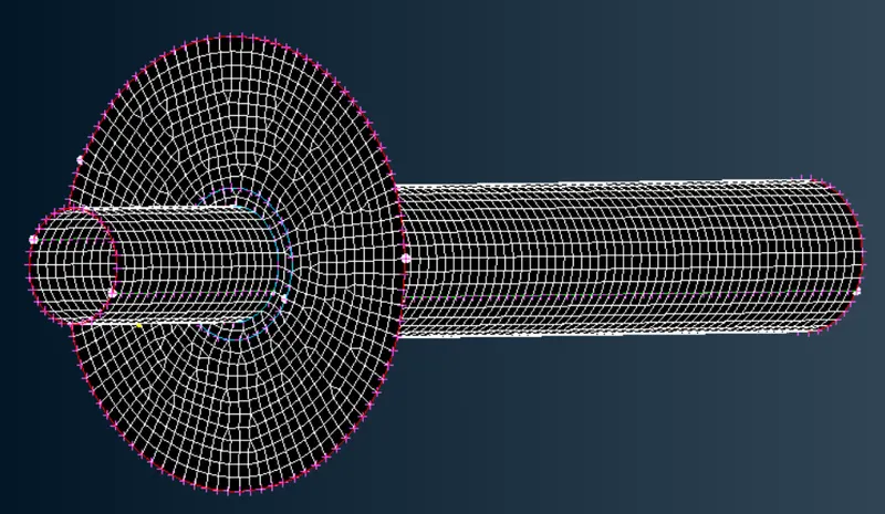
Figure 22 - Mid surface creation for other two parts
- Separate PIDs are created to the parts and thickness is assigned
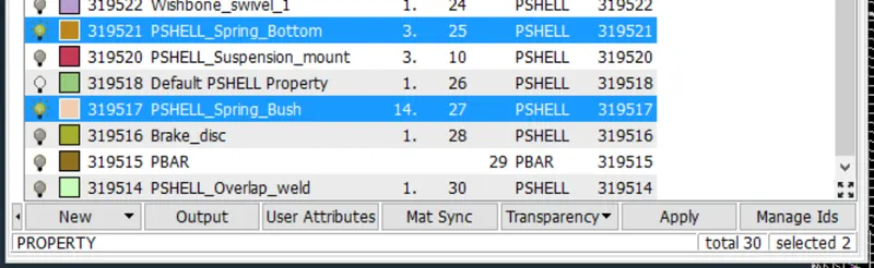
Figure 23 - Thickness assignment
Creating Spring using CBAR elements:
The meshing for spring is created as CBAR elements using the procedure stated in the challenge description and it is as follows:
- The middle curve for the spring contour is created using Topo --> Curves --> Middleoption
- The curves are connected using Topo --> Curves --> Connect --> Multioption
- COG point for the curve is created
- In Nastran tab, Elements --> CBARis selected
- In the element definition parameters window, “Orientation with nodes” is checked and pick selection is changed to Curve(Box)
- The middle curve and the COG point are selected
- Element length is given as 3mm
- New PID is created for the spring and in PBAR properties, the cross section of spring is entered
- After middle click, the spring as CBAR elements is created
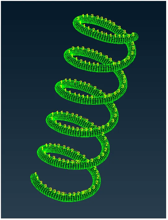
Figure 24 - Spring as CBAR elements
Creating connections:
The components in the model have mostly bolted connection and one connection is realized with weld connection.
1. Bolted connection:
The bolted connections were created using manual approach. First, the cluster RBE2 connection is created on the two faces where the bolted faces would contact and it is created as follows:
- Nastran --> Elements --> RBE2 --> Many Nodes is selected
- Slave Nodes are selected using “Loop” selection mode
- Automatic creation of master node is created using convex full centroid option
- New part is created in the model browser window (if needed)
The body of the bolt created using two node RBE2 elements and it is created as follows:
- Nastran --> Elements --> RBE2 --> Two Nodes
- The master nodes of two clusters are selected
- The part in model browser is selected or created new (if needed)
The bolted connection is created to realize connection between various parts in the model:
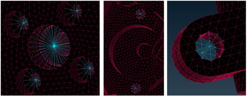
Figure 25 - Bolted connection
Two node RBE2 is created between the following parts:
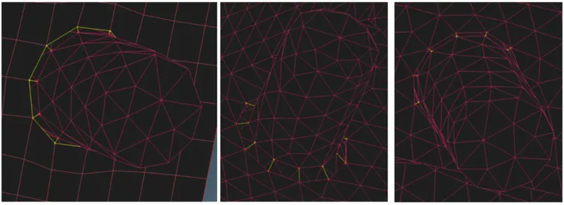
Figure 26 - 2 Node RBE2 connection
2. Welded connection:
Welded connection is created between the mounting bracket and the suspension spring holder:
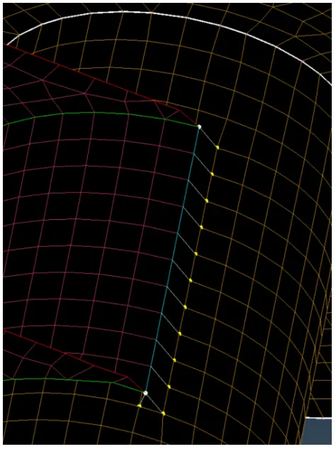
Figure 27 - Welded connection
The steps are as follows:
- The edge where the mounting bracket would be welded to the suspension spring holder is converted to curve using Topo --> Curves --> Cons2Curve
- Using Convert --> Curves --> Seam line --> Select Curve, the start and end of the seam weld line is defined
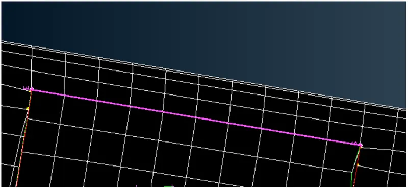
Figure 28 - Start and end seam line for welded connection
3. In the connection manager, following things are entered:
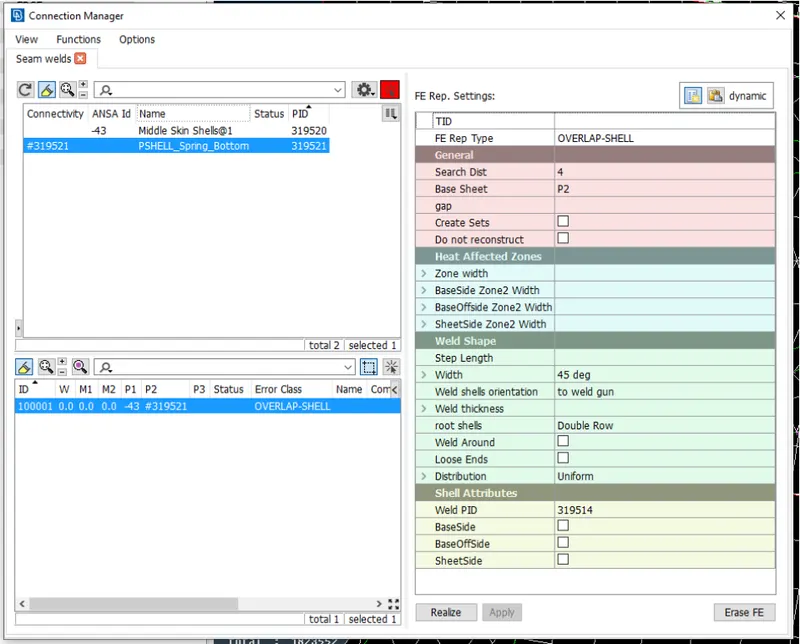
Figure 29 - Connection manager for welded connection
4.A new PID for the overlap weld shell is created
Create symmetrical side of the model:
- Using Transform --> Copy --> Select entities, the elements to be transformed are selected
- In the copy entities window, Symmetry --> Mirror 3 Points plane is selected
- Then the three mirror points in the model is selected and then Apply is clicked
- The symmetrical side of the model is created
The final model is as follows:
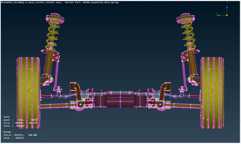
Figure 30 - Final model
Learning Outcomes:
In one single model, all the concepts which were taught in the preprocessor ANSA course has been used in the model. The concepts used are as follows:
- Geometry clean up
- PID assignment for each part in the model
- Generate mid surface for components with uniform thickness less than 5mm and thickness assignment for the components
- Solid meshing of non-uniform thickness components
- Creation of appropriate connections between the parts
- Creation of CBAR element for spring
- Using the symmetry option in Transform for copying the mesh and other elements on one side to the other symmetrical side of the model, which reduces the time for pre-processing
Conclusion:
The given model is checked for the geometrical errors and mesh with the given element Quality criteria. After meshing the component the thickness is assigned for mid surfaces. Tetra elements are used to model non-uniform thickness components. Also appropriate connections to connect the component as suggested in the Project-2 video are created (CBAR elements to model suspension spring to be used). At last Symmetry command is used to reflect the half finished model to the other side.