Project - 2 - Meshing on the suspension Assembly
MESHING ON THE SUSPENSION ASSEMBLY
AIM :-
Perform meshing and deploy connection for a suspension system
OBJECTIVE:
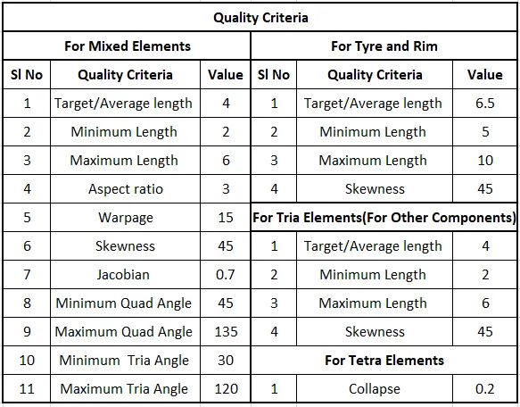
For the given assembly, check for the geometrical errors and mesh with the given element Quality criteria. After meshing the component, the thickness has to be assigned for mid surfaces. Use tetra elements to model non-uniform thickness components. Also, use connections to connect the component.
INTRODUCTION:
What is suspension?
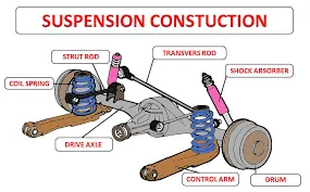
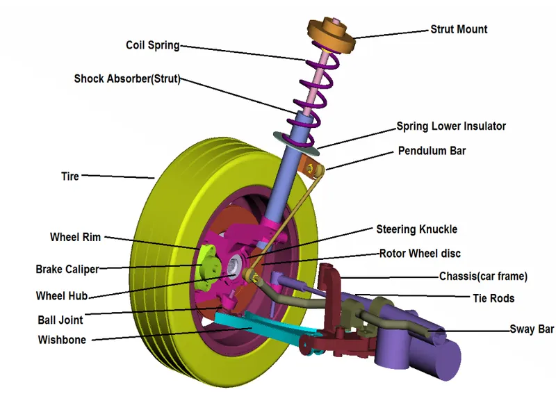
A system of mechanical linkages, springs, dampers that is used to connect the wheels to the chassis is known as a suspension system. It has usually done two works-controlling the vehicle’s handling and braking for safety and keeping the passengers comfortable from bumps, vibrations, etc.
Functions of Suspension System
- To prevent the stability of the vehicle in pitching or rolling while in motion.
- To safeguard the occupants from road shocks.
- A suspension system prevents the road shocks from being transferred to the vehicle frame.
- To provide good road holding while driving, cornering, and braking.
- To maintain proper steering geometry.
PROCEDURE :
1)Import .IGS File of Suspension Assembly in ANSA Workbench
2)Separation of Parts and Assign New Individual PID.
3)Geometrical Cleanup and Topology
4)Defeaturing
5)Surface Meshing
6)modelling of the 3d mesh component
7)Check for Quality Criteria
8)onnection
1)Import .IGS File of Suspension Assembly in ANSA Workbench
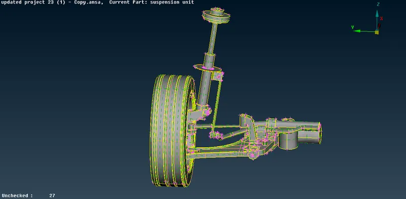
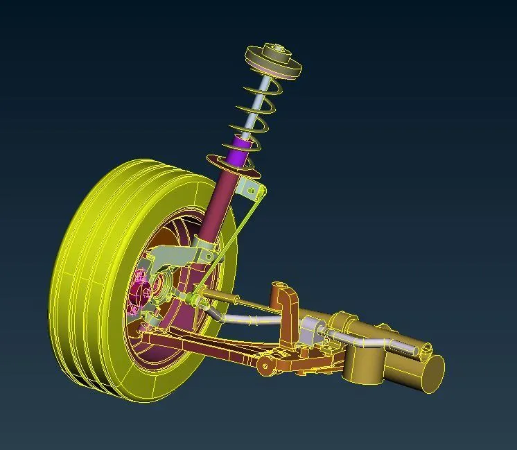
- Import the Suspension Assembly.IGS into the ANSA Workbench as shown in fig
- Change the Mode to Topo and Entity .
- Set the proper orientation as shown
- Change the perimeter length to 1(MESH>PERIMETER>LENGTH)
2)Separation of Parts and Assign New Individual PID.
Each Component is separated from the Assembly and give the Separate PID individually as shown in fig
3)Geometrical Clean up and Topology
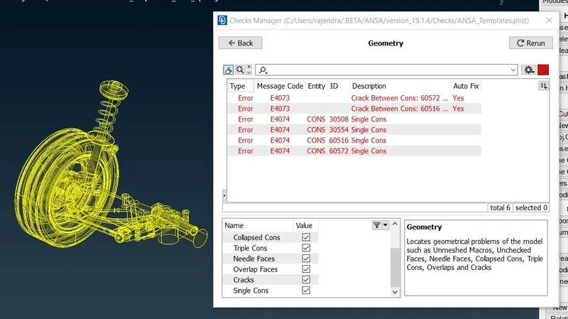
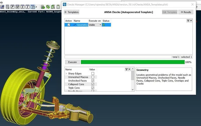
- Check all the geometry errors in the checks manager(Checks>Geometry>Execute) as shown in Fig
- Eliminate All the Triple Cons and Cracks between 2 Surfaces by releasing the triple cons and applying topo as shown in Fig
4)Defeaturing
In this step Change the Perimeter Length with reference to the Given Quality Criteria i.e. Average Length=1mm in this Component.(MeshMode>Perimeters>Length).Delete all the unwanted Cons.Faces and Ensure the distance between the Two Cons are more than given target length.
5) Extraction of Mid Surface
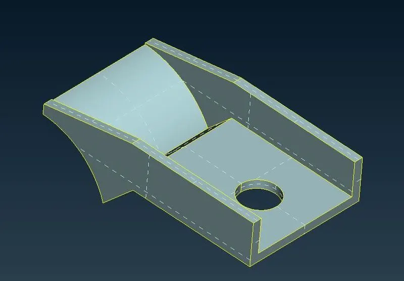
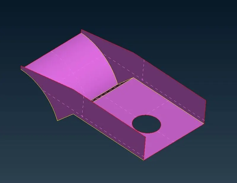
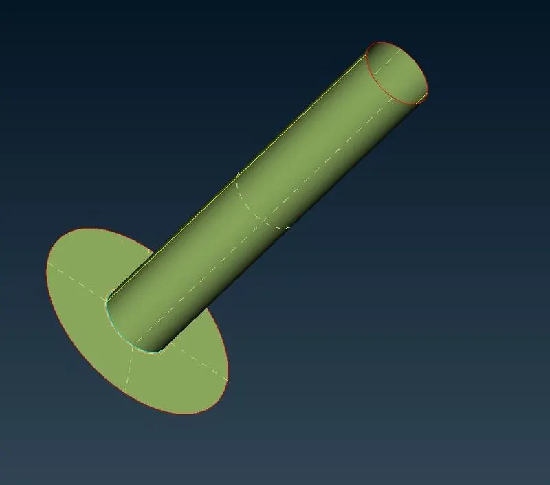
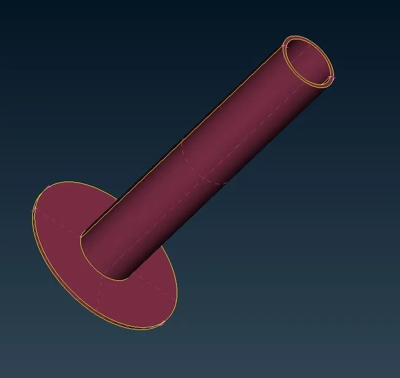
- Check for the Component for which we need to extract the Mid Surface( Thickness Less than 5mm) as shown in fig 4.1
- Mid surface is taken manually as the component has varying thickness which is too less which causes quality criteria failure in the auto mid.Offset Command (Topo Mode>Faces>Offset) in which we have to select the faces for which we need the mid surface and later we need to input the offset value
6.modelling of the 3d mesh component
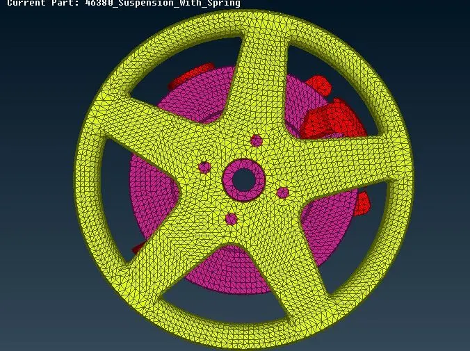
The remaining parts here are to be tetra meshed as they have a thickness above 5mm
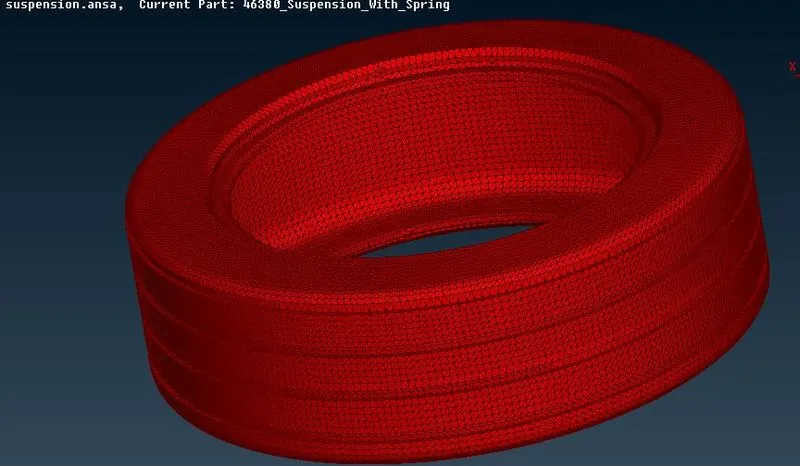
Firstly we mesh the components using tria and ortho trias elements respectively with a target of 4 mm. Ortho Trias are generally used on features such as fillets, chamfers etc for better mesh capturing
Then a volume is defined for each component using Vol Mesh->Define option and then the property is defined using Vol Mesh-> List and then using the remesh option using the Tetra rapid/Tetra FEM algorithm we can convert the tria mesh to tetra mesh
7.connections:
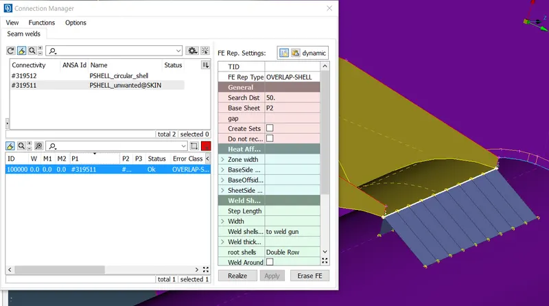
Here we can deploy a seam weld. This can be achieved by creating a curve and then defining the curve as a seam line. Then via the connection manager selecting P1 and P we can get it realized
For bolt connection we first connect the elements using NASTRAN->RBE2-> Many Nodes and the stem representation can be achieved using two-node rbe2
Similarly, all other connections are deployed using RBE2 option
Finally the component can be mirrored to obtain the full suspension assembly using the Transform->Copy->Symmetry
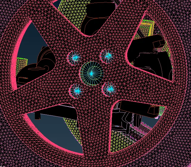
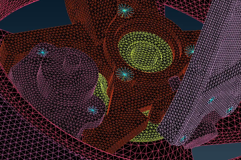
modelling of spring into 1d element using CBAR connector
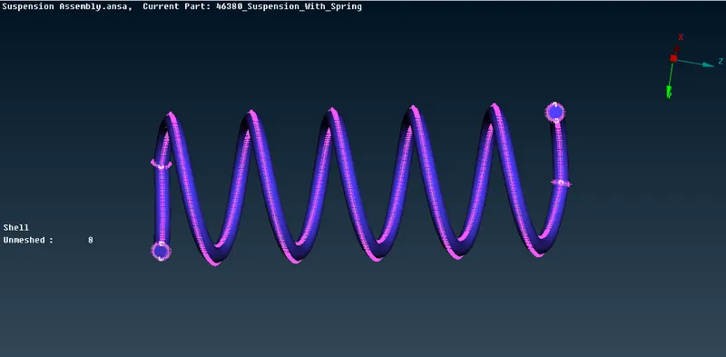
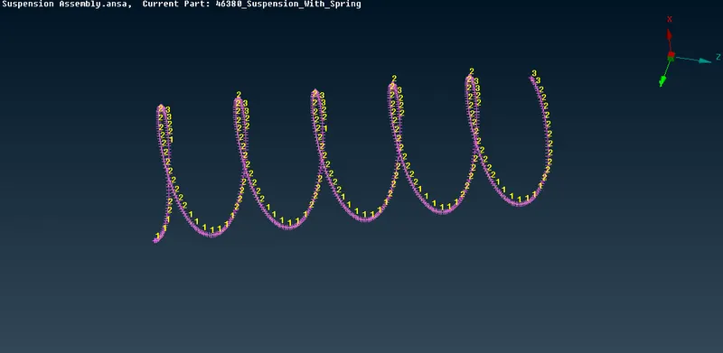
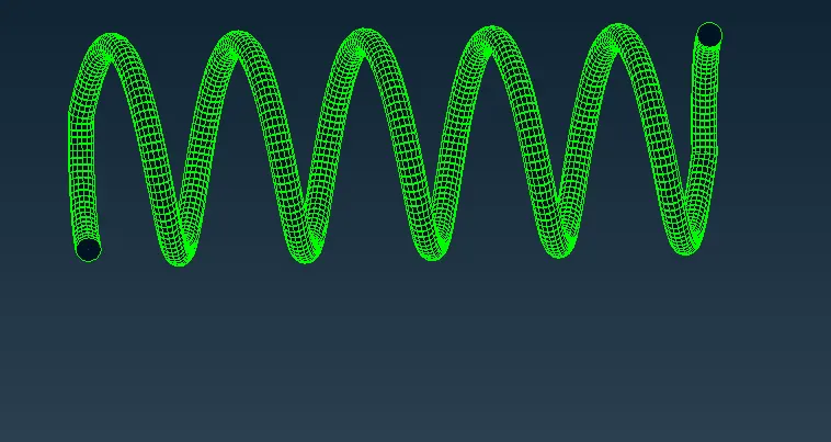
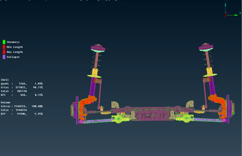
complete view of suspension assembly after symmetry operation
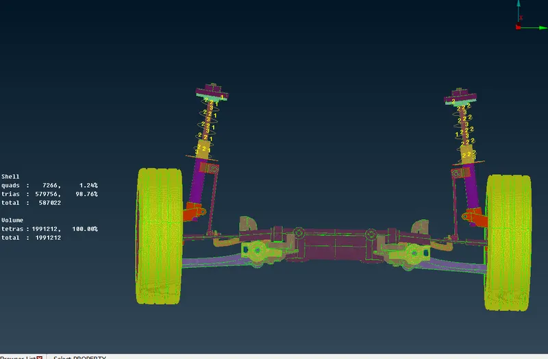
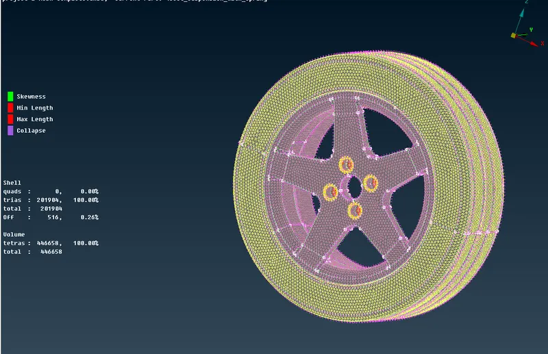
images with quality criteria
LEARNING OUTCOMES:
- Learned to fix the geometrical errors
- Learned to extract the mid surface for the uniform thickness component by casting and manual methods.
- Learned to perform the tria shell mesh
- Learned to fix the errors in the mesh using various tools.
- Got the idea about the errors in the volume mesh and how to fix them.
- Learned about the TETRA FEM and TETRA rapid.
- Learned to defeature the area in order to avoid errors in meshing.
- Learned to fix the dips and kinks in a volume mesh.
- Learned to deploy the connections using the RBE2 many and two nodes.
- Learned to mirror the component using the TRANSFORM tool.
Conclusion
- Got the complete exposure of the pre-processing steps that can be performed in ANSA which includes Importing model, Geometry cleanup, Mid-Surface Extraction, Element Cleanup, Assigning PIDs. Surface meshing for 3-D meshing, Penetration & Intersections errors, Volume Mesh, Connections, Transformation.
- Exposure to handle assembly in ANSA
file link
https://drive.google.com/file/d/1CHkrDwHtxlERfYAXBbRuh20wwp_kjILR/view?usp=sharing