Project - 2 - Meshing on the suspension Assembly
Project 2: Meshing on the suspension Assembly
Aim: Checking the given Suspension model for geometrical errors and mid surface extraction for component with uniform thickness components and tetra meshing of the other components with the given mesh quality criteria in addition to connections.
Given model: Suspension model
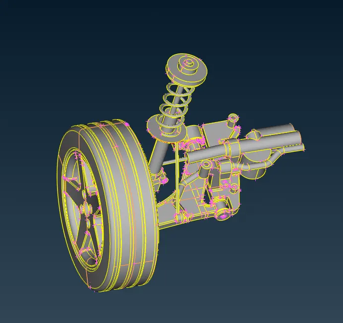
Parts include in the model:
1.
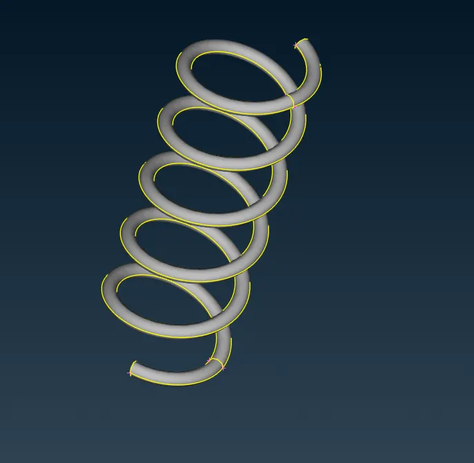
2.
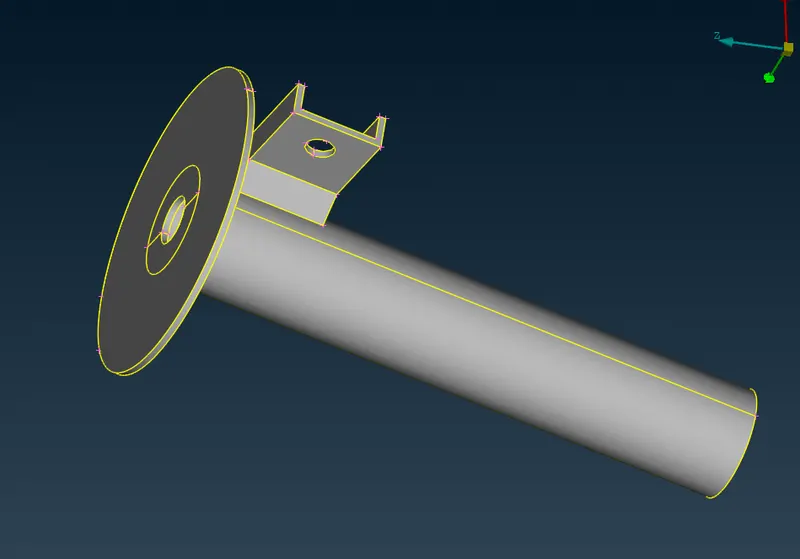
3.
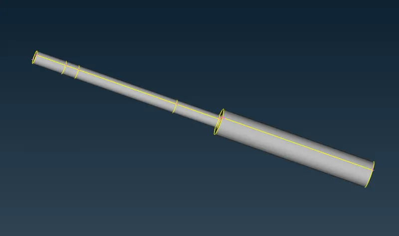
4.
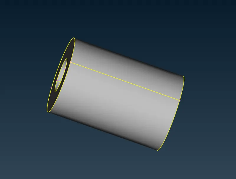
5.
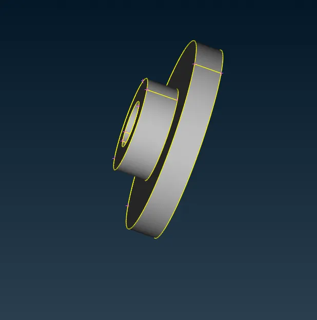
6.
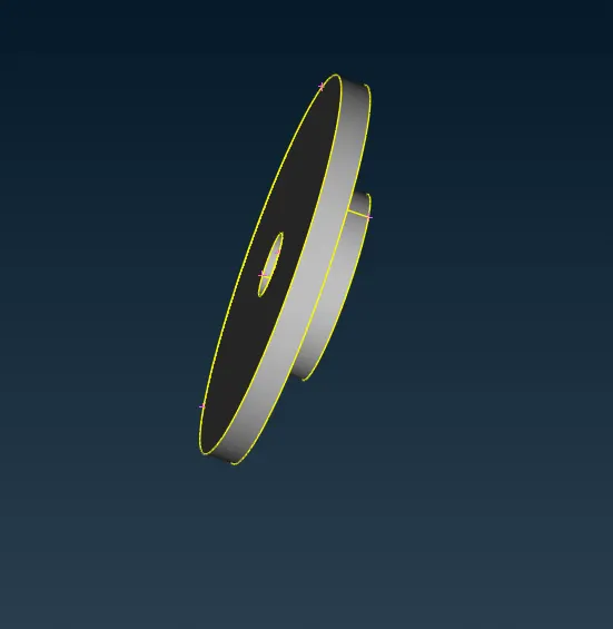
7.
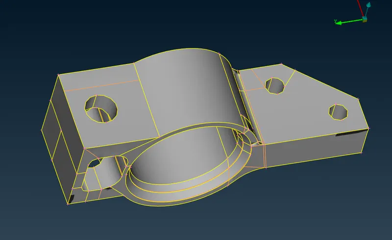
8.
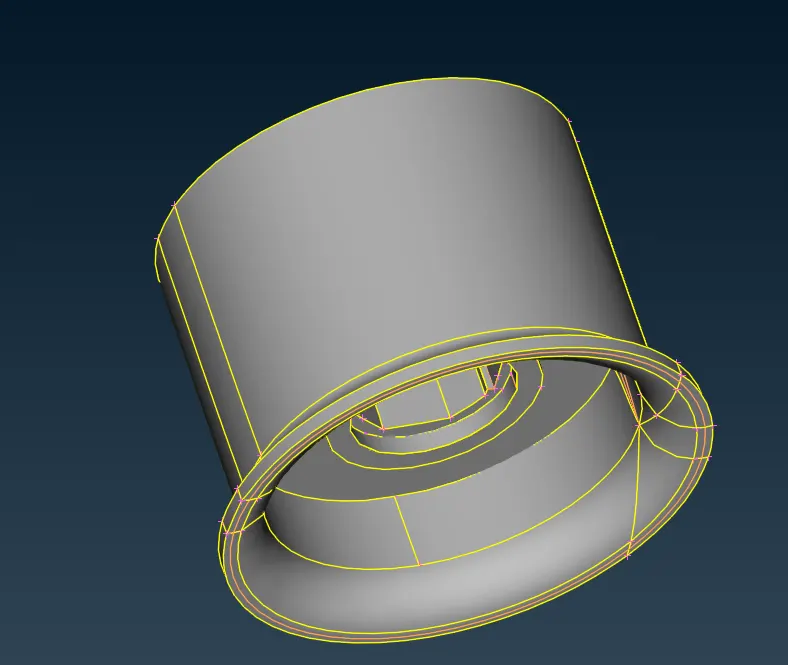
9.
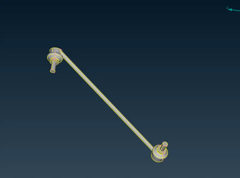
10.
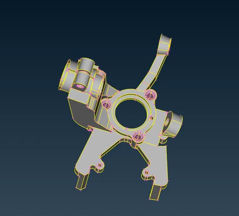
11.
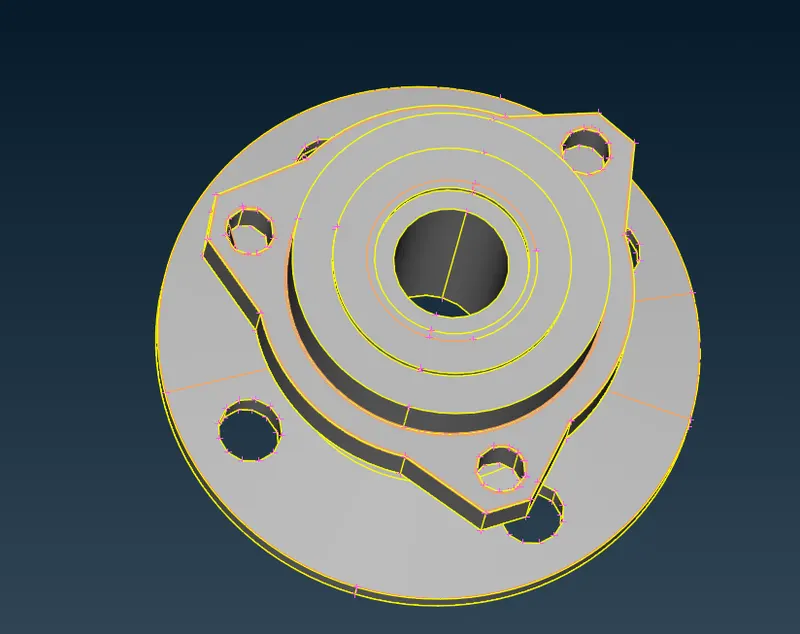
12.
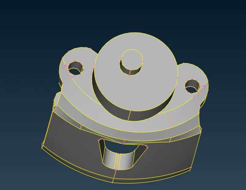
13.
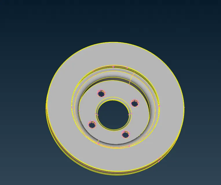
14.
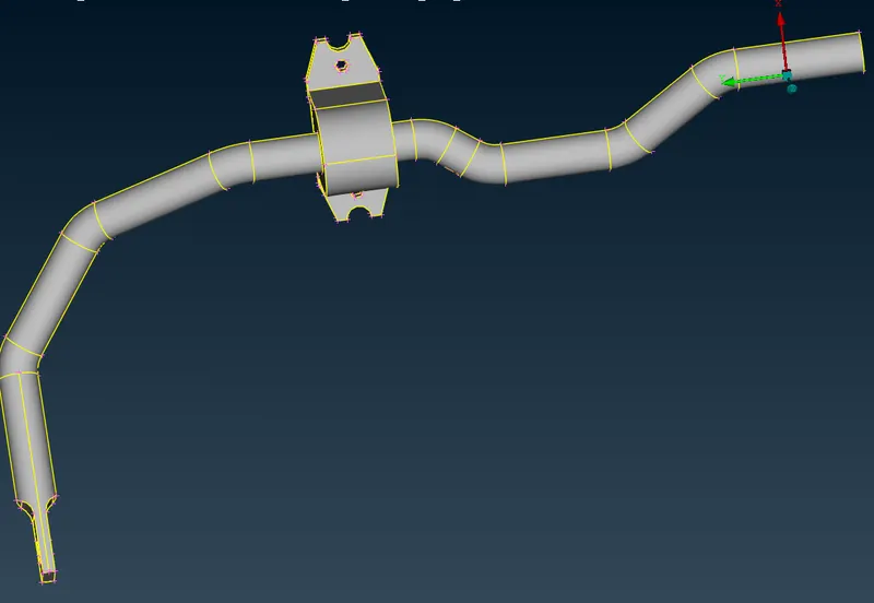
15.
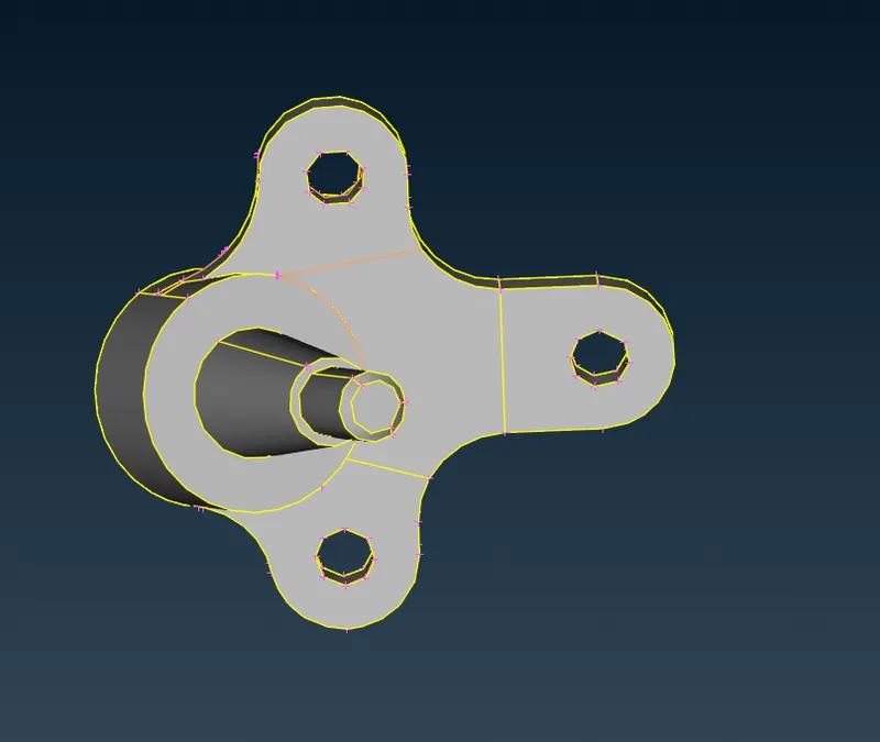
16.
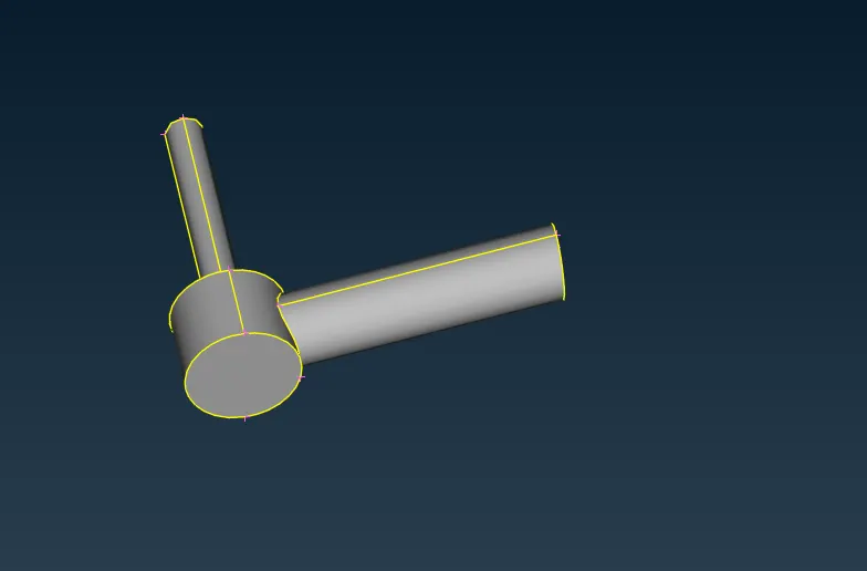
17.
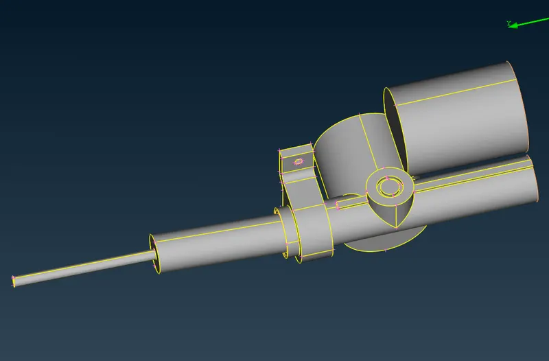
18.
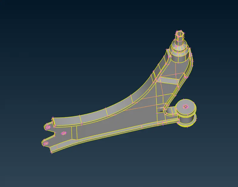
19.
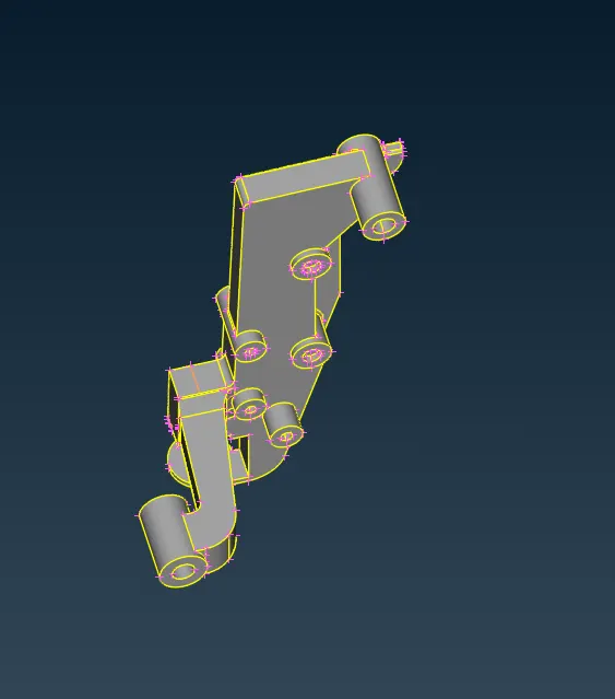
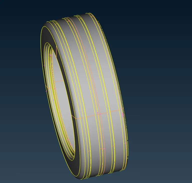
20. Tyre
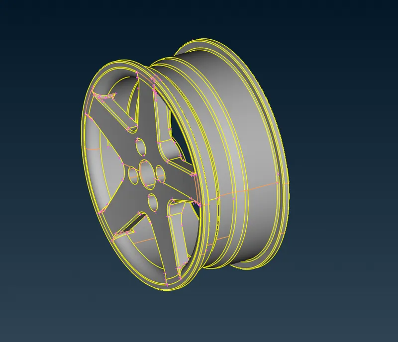
21. Rim
Given mid surface mesh Quality criteria for components with uniform thickness less than 5mm (Mixed Elements):
|
S.No |
Quality Criteria |
Value |
|
1 |
Target/Average length |
4 |
|
2 |
Minimum Length |
2 |
|
3 |
Maximum Length |
6 |
|
4 |
Aspect |
3 |
|
5 |
Warpage |
15 |
|
6 |
Skewness |
45 |
|
7 |
Jacobian |
0.7 |
|
8 |
Minimum Quad Angle |
45 |
|
9 |
Maximum Quad Angle |
135 |
|
10 |
Minimum Tria Angle |
30 |
|
11 |
Maximum Tria Angle |
120 |
Given surface mesh Quality criteria for Tyre and Rim components (Tria Elements):
|
S.No |
Quality Criteria |
Value |
|
1 |
Target/Average length |
6.5 |
|
2 |
Minimum Length |
5 |
|
3 |
Maximum Length |
10 |
|
4 |
Skewness |
45 |
Given Surface mesh Quality criteria for components with Nom-uniform thickness other than Tyre and Rim (Tria Elements):
|
S.No |
Quality Criteria |
Value |
|
1 |
Target/Average length |
4 |
|
2 |
Minimum Length |
2 |
|
3 |
Maximum Length |
6 |
|
4 |
Skewness |
45 |
Given Volume mesh Quality criteria for Non Uniform Components (Tetra Element):
|
S.No |
Quality Criteria |
Value |
|
1 |
Tet Collapse |
0.2 |
Procedure steps followed:
- Checking for Geometrical errors and fixing them for all different components
- Meshing Component 1 using beam element
- Extraction of Mid Surface of sub assembly Component 2 and meshing using Batch mesh
- Surface Meshing of other components using Batch mesh for given quality criteria
- Deploying Seam weld and bolt connections between components
- Define volumes for seperate non uniform parts
- Solid meshing using unstructured (tetra) mesh for all the volumes
- Assigning thickness to mid surface meshed sub Assembly component 2
Procedure:
- Checking for Geometrical errors and fixing them for all different components
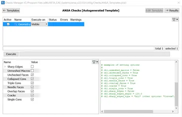
After importing the given model into ANSA, checking for geometry cleanup is done from
Tools -> Checks -> Geometry
Before Executing Geometry check After Executing Geometry check
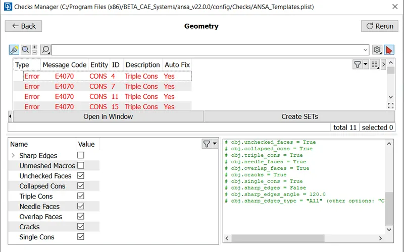
After Geometry cleanup
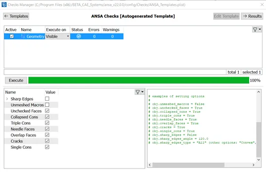
These errors are solved by Auto fixing them through clicking on actions icon -> Fix
- Meshing Component 1 using beam element.
The component 1 is a spring part and this is modeled and meshed using 1D beam element
This is done by forming middle curve which follows profile of the spring by using
TOPO -> Curves -> Middle
Then using Nastran Deck -> Elements -> CBEAM and Selecting the curve and On COG point of curve by checking "Orientation with node" and using Curve (box)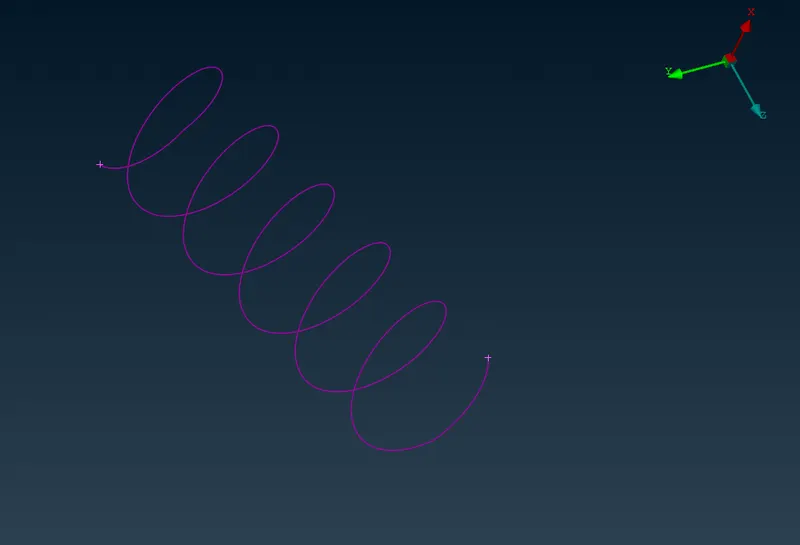
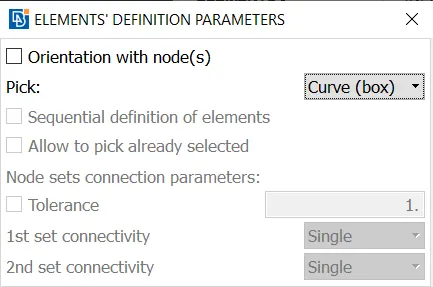
specifying the element length and assigning a different PBEAM PID and confirming it.
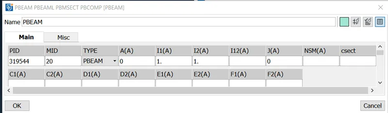
Assigning A(A) by using '?' and giving the radius from the model
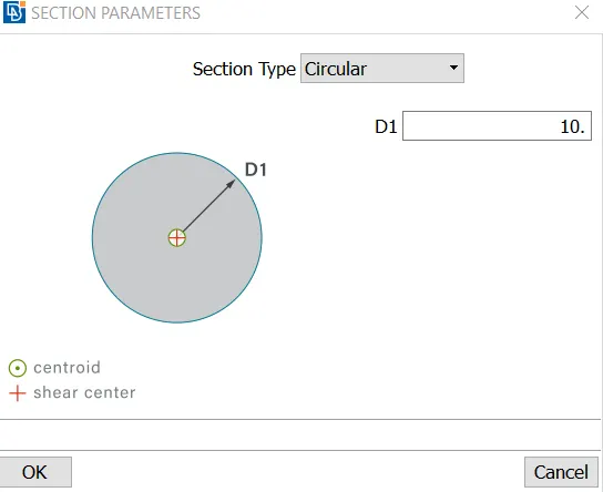
By Confirming the PID and selecting the direction from
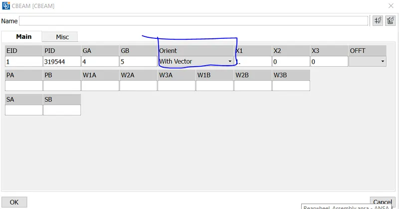 Changing orient to 'With node Z- axis'.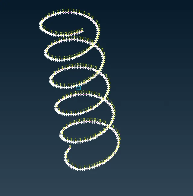
1D beam elements are created.
- Extraction of Mid Surface of sub assembly Component 2 and meshing using Batch mesh
The component 2 has uniform thickness and is less than 5 mm. So we extract mid surface using
TOPO -> Faces -> Offset and selecting faces and confirming the offset distance which is half of the exact thickness of the component.
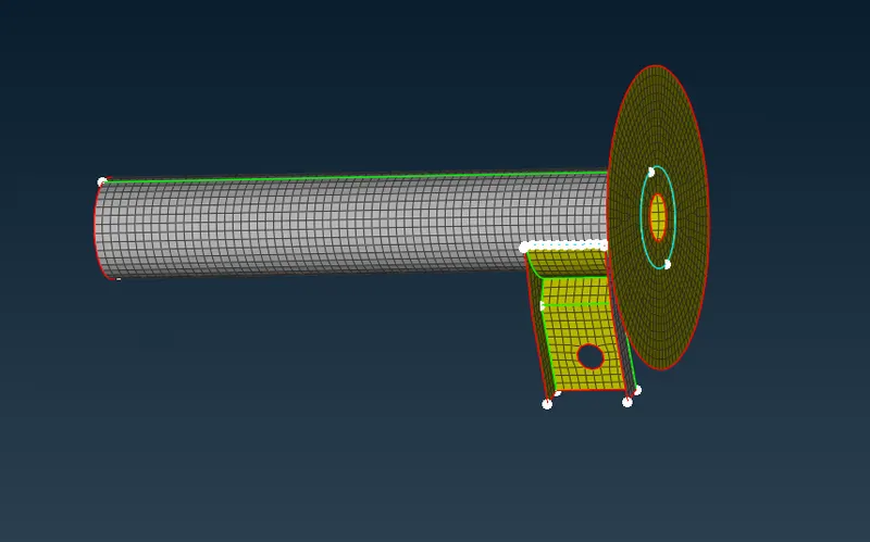
The mid surface extracted is shown below
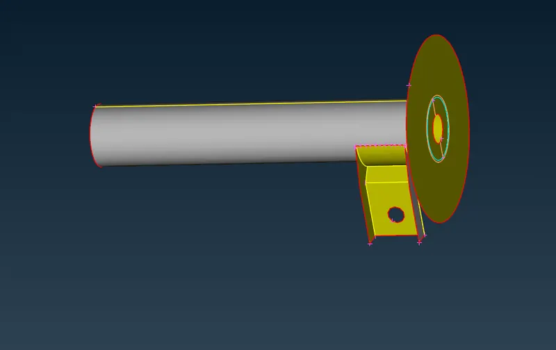 Extending surfaces to intersect as to appear similar to model given.
Meshing of theses components is done using Batch Mesh and Selecting contents using PIDs and editing Quality criteria as given and the meshing parameters as mixed elements.
The meshed mid surface is shown below.
- Surface Meshing of Component 3 to 19 using Batch mesh for given quality criteria
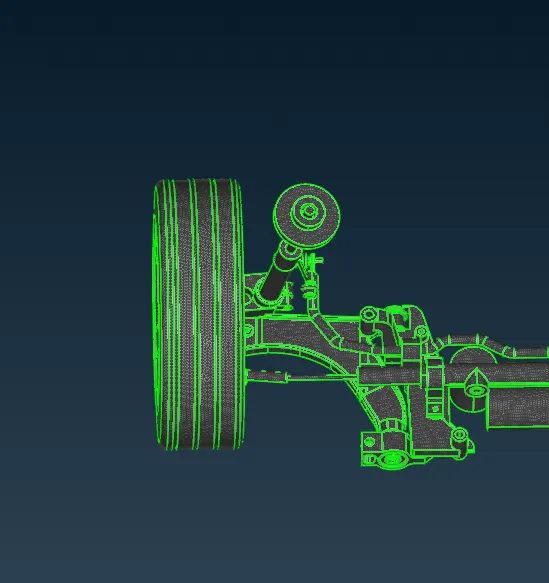
The components other than above components are having non-uniform thickness and is greater than 5mm. For these kind of components we go for solid meshing and for solid meshing surface meshing is to be done. This done using Batch meshing.
The qulality criteria and mesh parameters are different for tyre, rim and other components and so we use different meshing scenes for different quality criteria.
So the given criteria are updated with the given values and meshing is run.
The meshed models with assembly are shown below.
Since the given component is only half of the suspension model we use symmetry option from Transform -> Copy and selecting the half of the suspension model along with mid surface component and 1D beam element to complete the other half which deleting the overlapping surfaces.
The complete surface meshed model is shown below.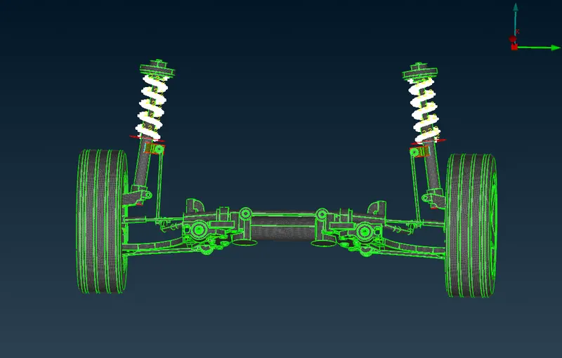
- Deploying Seam weld and bolt connections between components
After the surface meshing is done th connections are deployed.
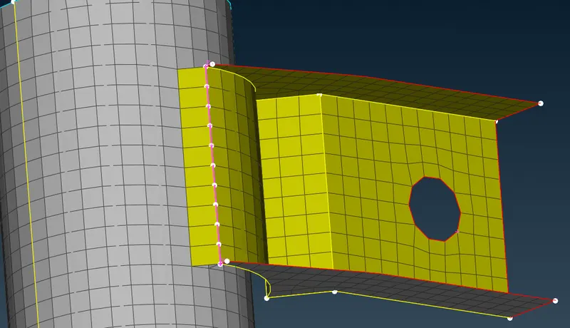
Here we use seam weld connection in components 2.
This is done by TOPO -> CONS2Curve by creating a curve at the edge and converting to seam line.
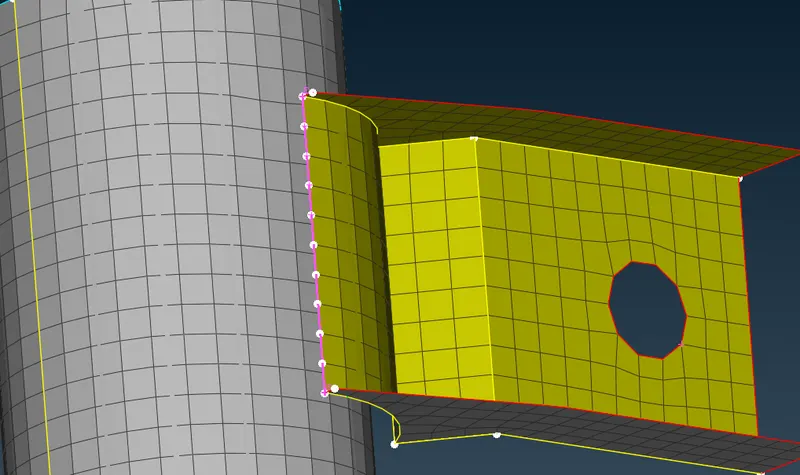 By projecting the perimeter onto curves surface the creation of wel is done by minimla disturbace to the base mesh by Mesh -> Shell mesh -> Project
By Using connection manager the overlap shell is realized between the two different PIDs
The bolt connection between other components are done using
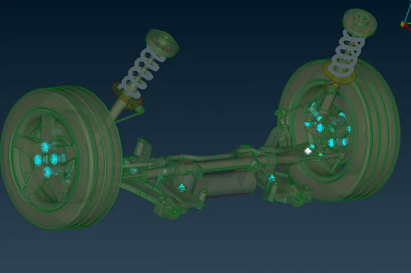
Nastran -> Elements -> RBE2 -> Many nodes and Two Nodes due to small mis alignment in CAD for the holes using
The hole are selcted using Loop option and the BOLT connection is used for between Top and Bottom surface nodes.
The model using connection is shown below.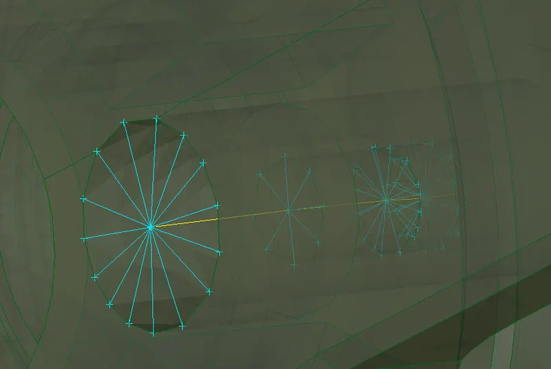
- Define volumes for seperate non uniform parts
After surface meshing and connections are done we go for Volume meshing for NOn-uniform components using
Volume Mesh -> Volume -> Define
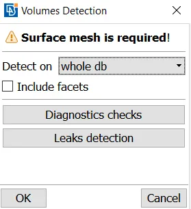
This defining volume can be done individually by changing detect on from 'whole db' to 'visible' or 'selected'.
ANSA detects the volume and after that
New PID for volumes are assigned.
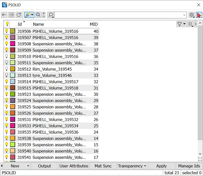
- Solid meshing using unstructured (tetra) mesh for all the volumes
Meshing using Tetra Rapid is done.
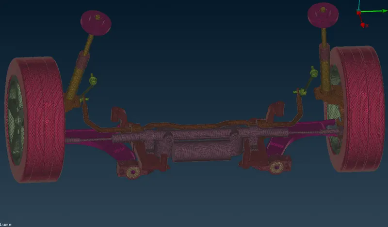 The volumetric tertra mesh is shown above.
 - Assigning thickness to mid surface meshed sub Assembly component 2
After volume meshing assigning of thickness to mid surface is done in property dialog box. By double clicking on the PID
The draw shell as solid is switched on to view thickness.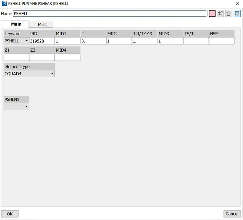 Changing the value of T to the thickness value.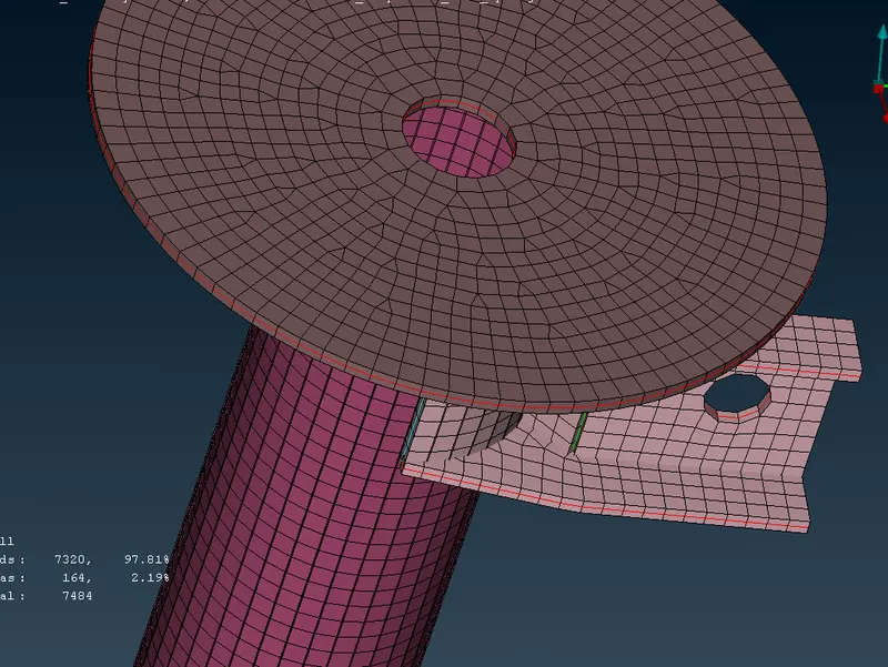
Learning Outcomes:
- Cleaning of Geometry.
- Meshing of component using Spot mesh Algorithm and Batch meshing and using different 2D elements (tria, Ortho/tria).
- Defining volumes and Unstructured Solid meshing.
- Deploying connections between different components
Conclusion:
Geometry cleanup, Mid surface extraction, Solid tetra meshing of given Suspension model is done using ANSA v22.0