Project - 2 - Meshing on the suspension Assembly
AIM:
To perform solid meshing on the given suspension model and deploy connections wherever necessary.
PROCEDURE:
1.First import the given suspension assembly model to the ANSA .
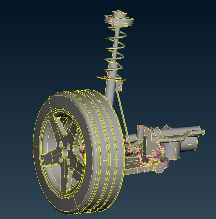
2.Perform a topo if necessary and check for any geometric irregularities .We can see that there are no errors and the model is quite clean.
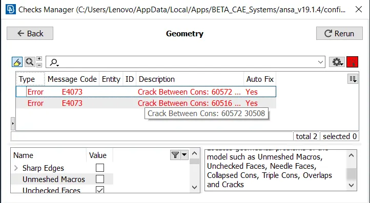
3. Now proceed for geomtrical checkup .Go to Tool Bars>>Checks>>Geometry.Here only two or three errors are there which can be fixed automatically by ANSA itself.Right click on the errors and click fix , now the errors will be fixed and the geometry is clean.
4.Now assign different PID's for all the parts .Go to Faces>>Set PID and select the part and form a new PID.
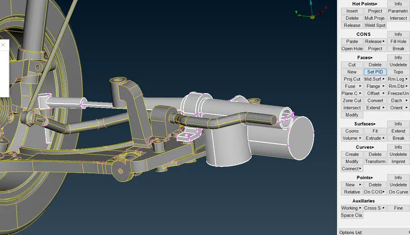
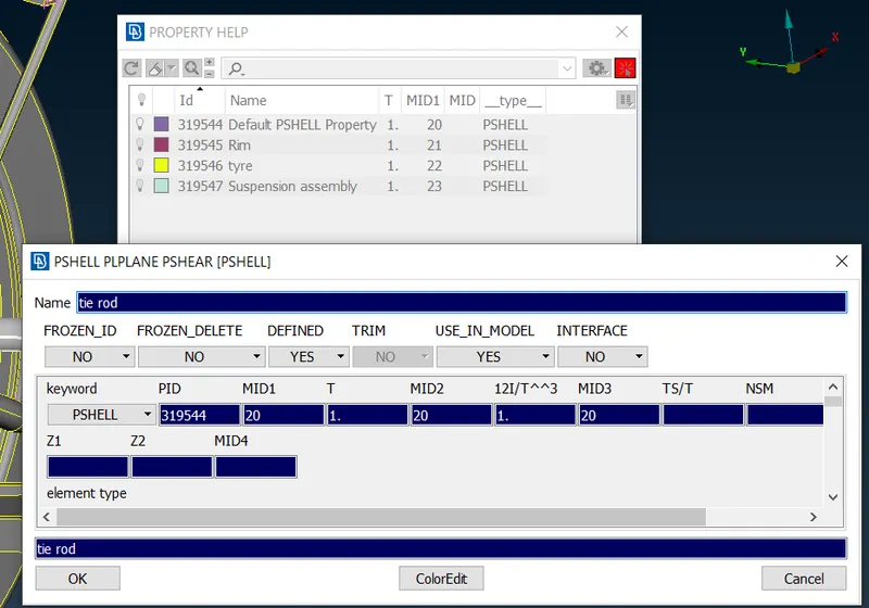
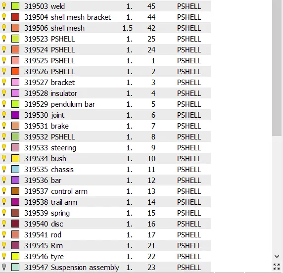
PID's CREATED
5.Now lets proceed for meshing.Here almost all the parts have thickness higher than 5mm , so we can proceed with solid meshing for all parts except two components.
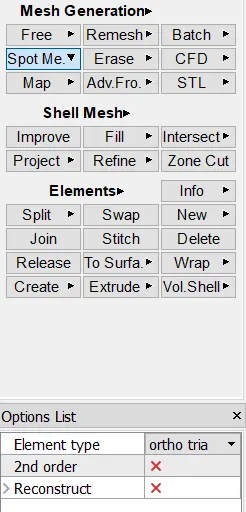
6.Start with tyre and rim components .First set the mesh and quality parameters and go to mesh module>>Mesh generation>>Spot mesh>>Select the areas.
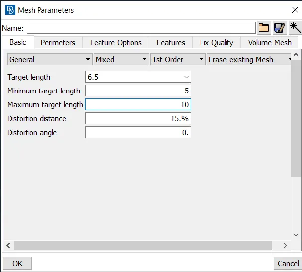
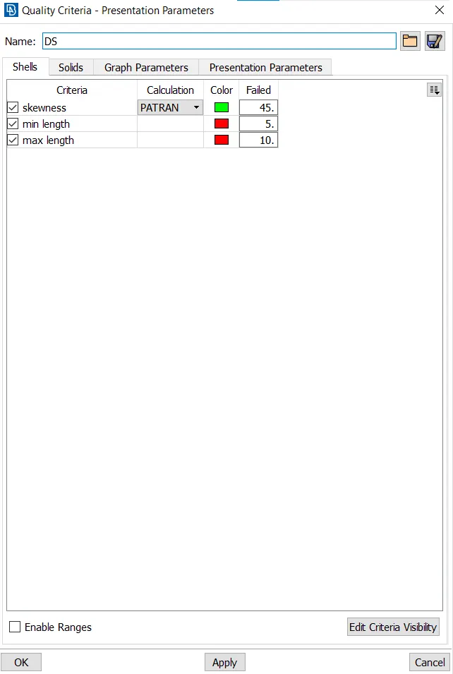
7.Set the perimeter and macro length as target element length for proper mesh generation.Then start meshing with trias for flat surfaces and ortho tria elements for curved surfaces.
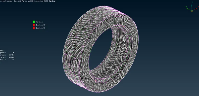
TYRE MESHED
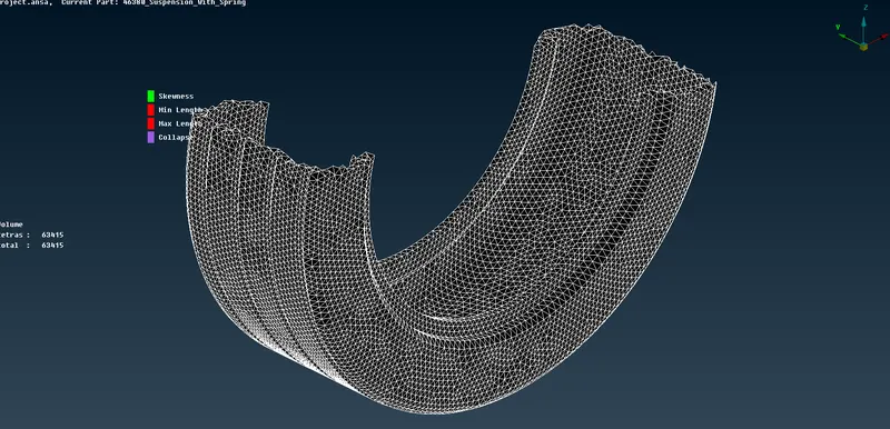
AFTER SOLID MESH
8.Then repeat the similar process for rim also with same quality and mesh parameters.Also check for tet collapse failure and correct them if necessary.
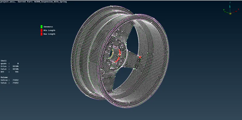
9.Now start solid meshing for components with thickness more than 5mm .Set the quality and mesh parameters.
Quality criteria for Surface Meshing of Non Uniform thickness components other than Tyre and Rim (Element type: Tria) :
|
S.No |
Quality Criteria |
Value |
|
1 |
Target/Average length |
4 |
|
2 |
Minimum Length |
2 |
|
3 |
Maximum Length |
6 |
|
4 |
Skewness |
45 |
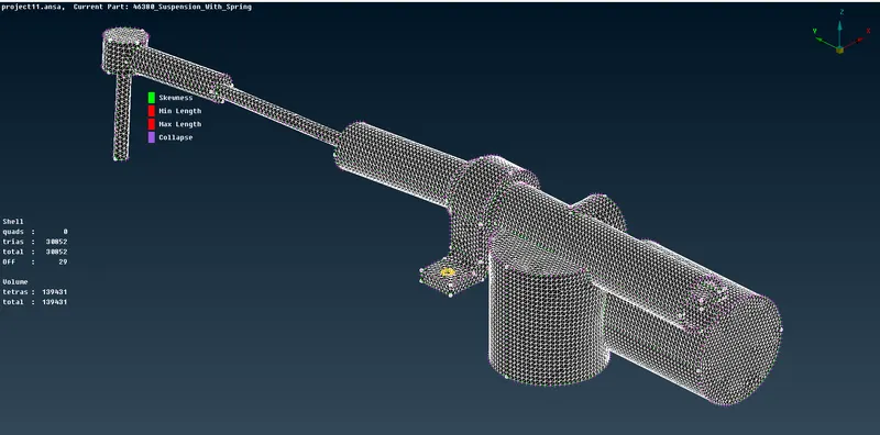
10.Now proceed with shell mesh for components with thickness less than 5mm.Extract a mid surface using offset option and set the mesh,quality parameters .Proceed with meshing without any off elements.
Quality criteria for Mid surfacing of Uniform thickness part which has thickness less than 5 mm (Element type: Mixed elements) :
|
S.No |
Quality Criteria |
Value |
|
1 |
Target/Average length |
4 |
|
2 |
Minimum Length |
2 |
|
3 |
Maximum Length |
6 |
|
4 |
Aspect |
3 |
|
5 |
Warpage |
15 |
|
6 |
Skewness |
45 |
|
7 |
Jacobian |
0.7 |
|
8 |
Minimum Quad Angle |
45 |
|
9 |
Maximum Quad Angle |
135 |
|
10 |
Minimum Tria Angle |
30 |
|
11 |
Maximum Tria Angle |
120 |
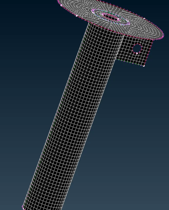
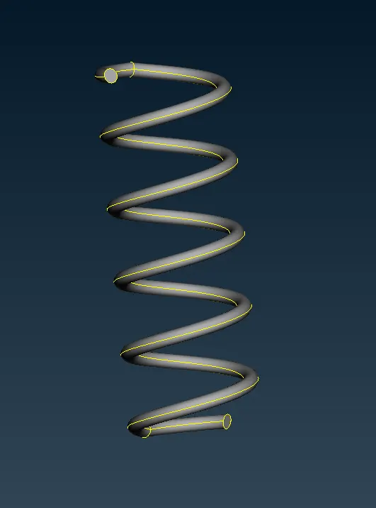
11.Now we have to deploy connections for the whole component.Start with the spring, we have to represent it with 1D bar element .
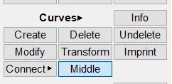
a.Extract a middle curve for the spring using Cuves>>Middle .
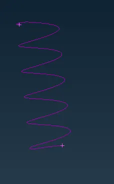
b.Create a COG point on the curve using Points>>On COG>>Edges command.
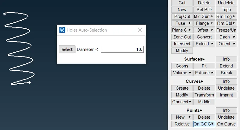
c.Now go to nastran deck>>Elements>>CBAR and select the curve(box) option and select the curve.
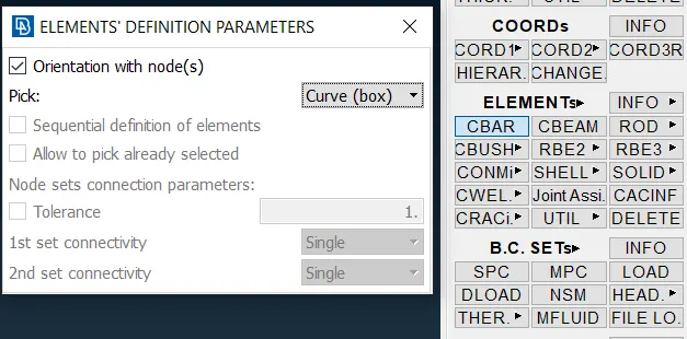
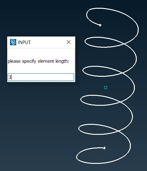
Select the node for orinetation
d.Create a new PBAR element and specify the radius as 5 and ANSA will calculate the all the values.
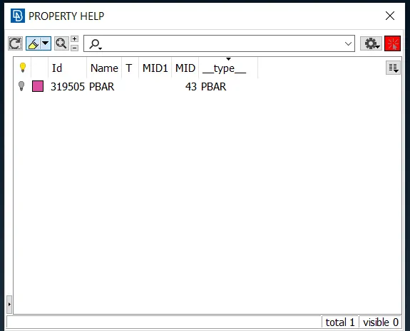
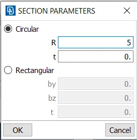
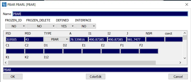
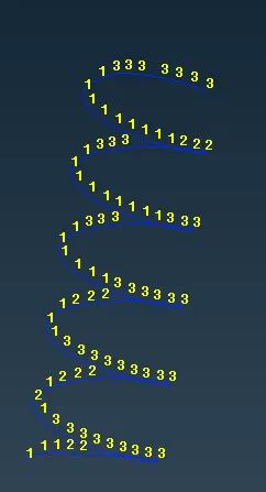
1D BAR ELEMENT
12.Now deploy RBE2 connections where bolts are required and where rigid connections are needed.To deploy go to Nastran deck>>Elements>>RBE2>>Many nodes.
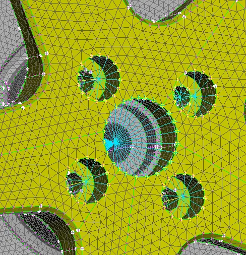
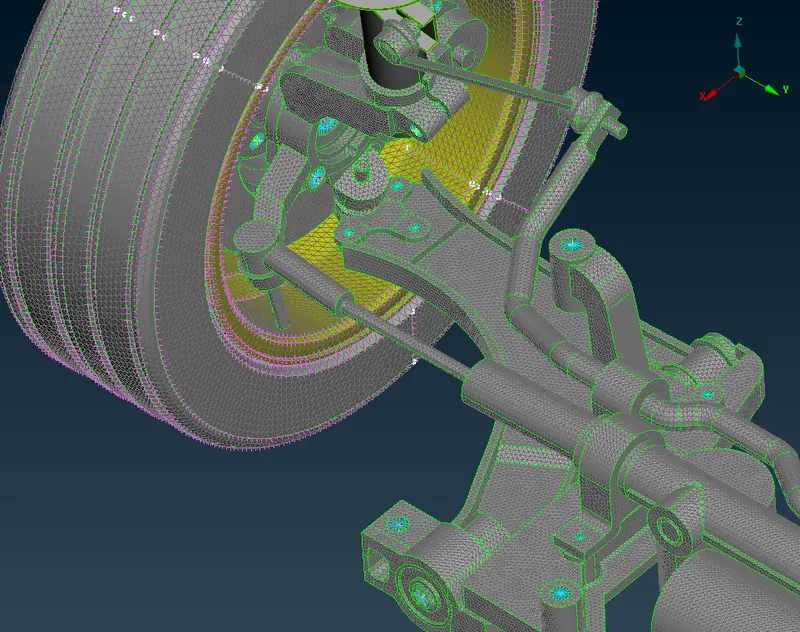
CONNECTIONS ESTABLISHED
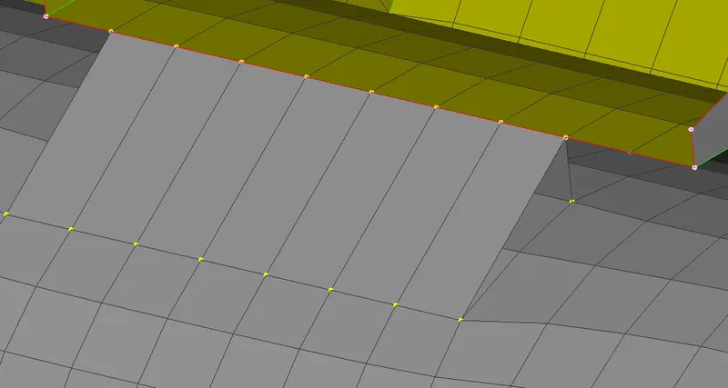
SEAM WELD CONNECTION
13. Now we have to reflect the whole component.Go to utilities panel>>Transform>>Copy.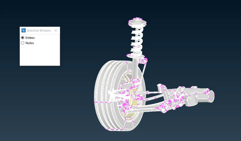
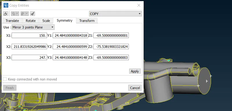
14.Now select the symmetry tab and select three nodes for reflecting.
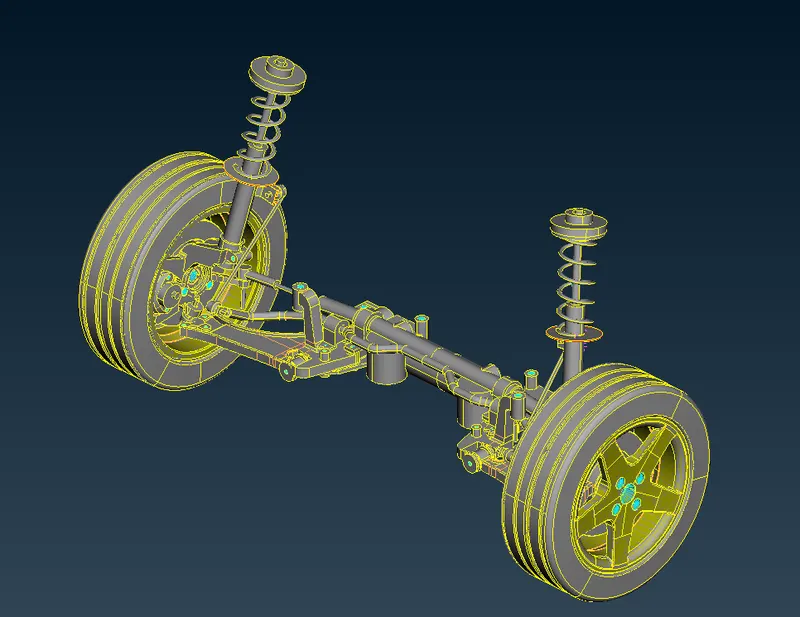
AFTER REFLECTING
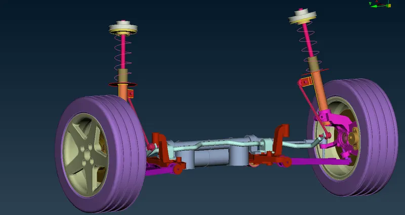
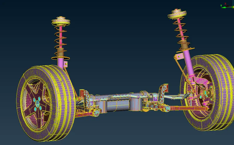
FINAL MODEL IMAGES
RESULT:
Thus the given suspension assembly model was meshed according to given quality criteria and connections are established.
LEARNING OUTCOMES:
1.Learnt to do 3D mesh properly for larger components with proper mesh flow.
2.Generate volume tetra mesh for components.
3.Fixing tet collapse and to represent spring as 1D bar element.