Project - 2 - Meshing on the suspension Assembly
AIM
To mesh the given Rear wheel component and give connections under the given quality criteria.
PROCEDURE
- Import the given component in the ANSA.
- First, use the topo to fix all the free edges.
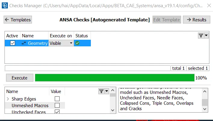
- And use check the geometry. If there is any error use the fix option to fix the issues or manually clean the issue.
VOLUME MESH
- First, check the thickness for all the components if the thickness is above 5mm done the tetra mesh.
- In the component, there is four different components are present, and separate and assign property to it by using SET PID.
- Clean the geometry which is below the given quality criteria or use the batch mesh the component the auto cleanup is done in the component automatically.
- Then mesh the component using spot mesh tria elements separately for all components.
-
Quality Criteria for Surface Meshing of Tyre and Rim (Element type: Tria) :
S.No
Quality Criteria
Value
1
Target/Average length
6.5
2
Minimum Length
5
3
Maximum Length
10
4
Skewness
45
Quality criteria for Surface Meshing of Non Uniform thickness components other than Tyre and Rim (Element type: Tria) :
S.No
Quality Criteria
Value
1
Target/Average length
4
2
Minimum Length
2
3
Maximum Length
6
4
Skewness
45
- Use shadow mode to view the error element presented in it.
- Use reconstruct option to change the mesh flow and minimize the error in it. And use the smooth option to smooth the mesh flow.
- By using these options clear all the error elements.
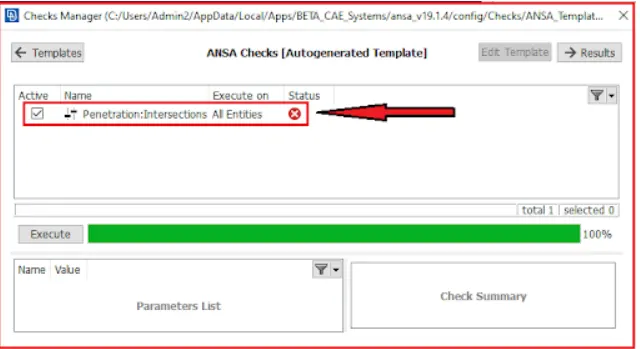
- After that go to volume mesh and define a volume for the component.
- Then volume mesh is done by unstructured mesh use Tetra rapid or Tetra FEM.
- By using this error is shown in the meshing because all the components are not attached to each other.
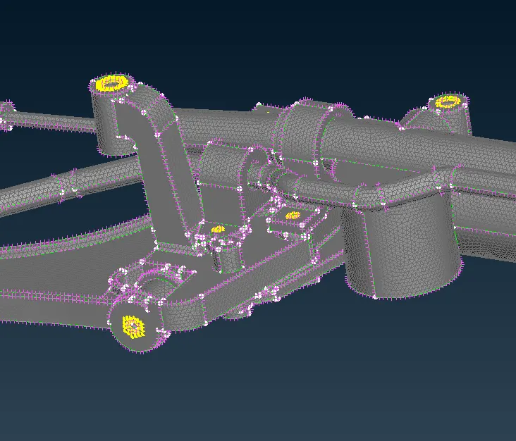
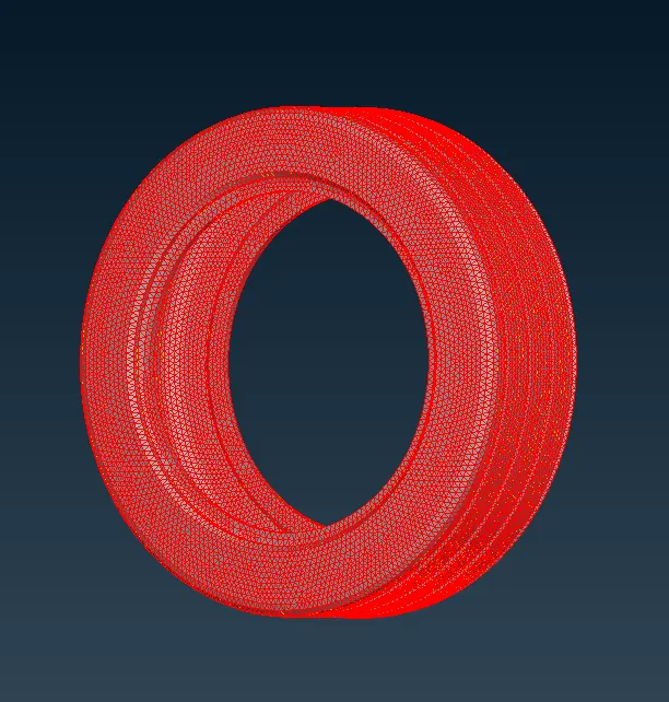
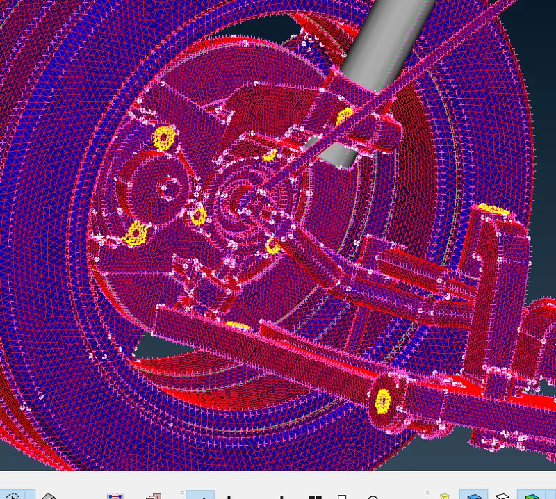
- So that use list option and select components and remesh one by one and change it to volume mesh.
- After meshing switch on the boundary option to see volume mesh.
- And use not option and cut the component to see if the volume is not.
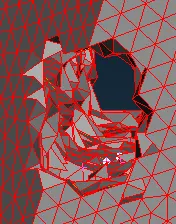
- If the volumes are all saved in one folder then separate the volume using the list option.
- And assign property as PSOLID to all the components separately.
- And also assign PSHELL to the 2d mesh components. Then save the component.
2D MESHING
- If the component is less than 5mm then go for 2d mesh.
- First, extract the mid surface for the component.
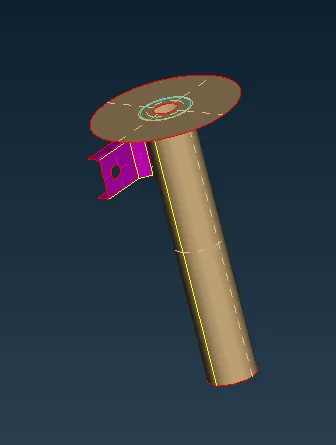
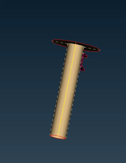
- Then change TOPO to MESH MODE and change the perimeter length 4mm for the whole component by length option in perimeter p
- Check all the surfaces by measure option if any surface is below 2mm use the JOIN or CUT option to defeture it.
- By using the align option change the nodes parallel to near nodes.
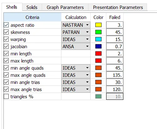
- And go to the criteria file and change the value by given quality criteria.
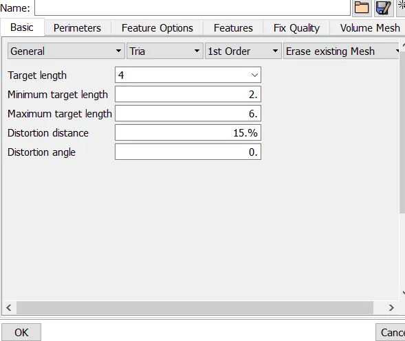
- Then give the value for the mesh parameter in the utility panel.
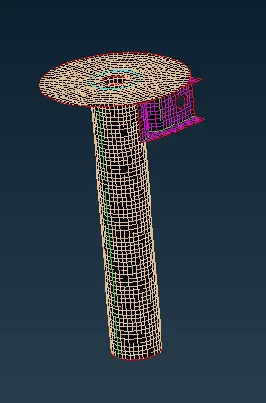
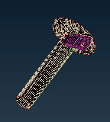
- Now generate the mesh for the given component by select the BEST option to mesh generation.
- Change the SHADOW to the HIDDEN mode to view the failed elements.
- By using the Reconstruct option and change the mesh flow properly.
- If there is any opposite tria or tria formed towards to perimeter must be changed by using the swap, split, reconstruct option to change it.
- And use the smooth option to smooth the mesh flow.

- This process is done for all other components.
- Then assign the property for the component in the database panel.
- Give the proper thickness to all components and assign it.
CONNECTIONS
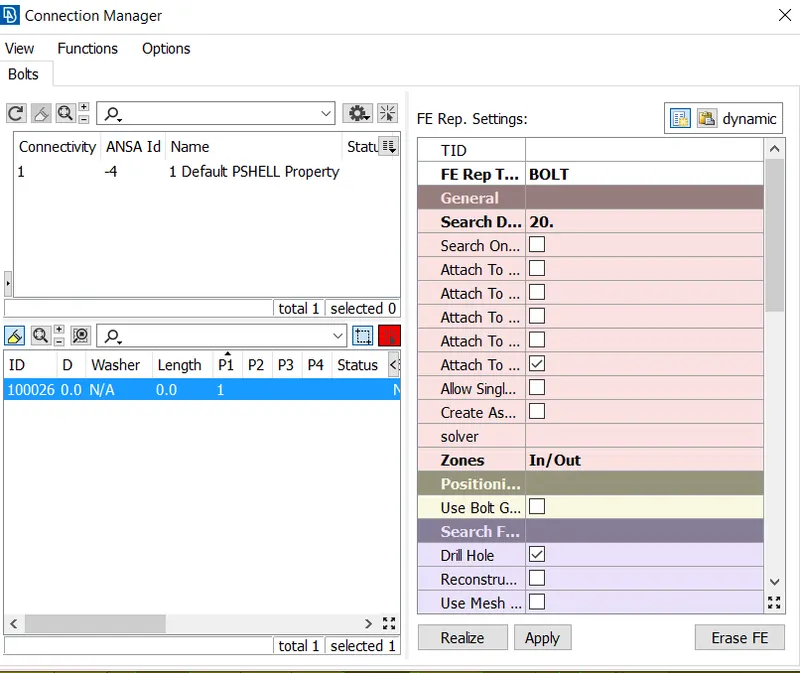
- By creating a bolt first create COG to the holes and convert to a 3D curve then go to connection manager and assign Rigid bolt to it.
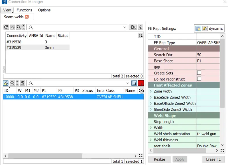
- For that first create a curve using features to curve option and create it then convert the curve into seam line and go to connection manager then create weld to it.
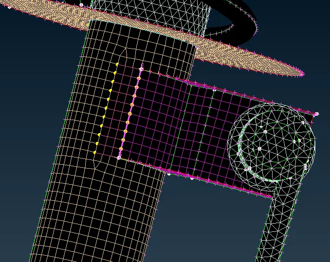
- RBE2 representation is given to connect the two parts. or use bolt to connect the components.
1D BAR ELEMENT
- For spring 1d element representation is given to it.
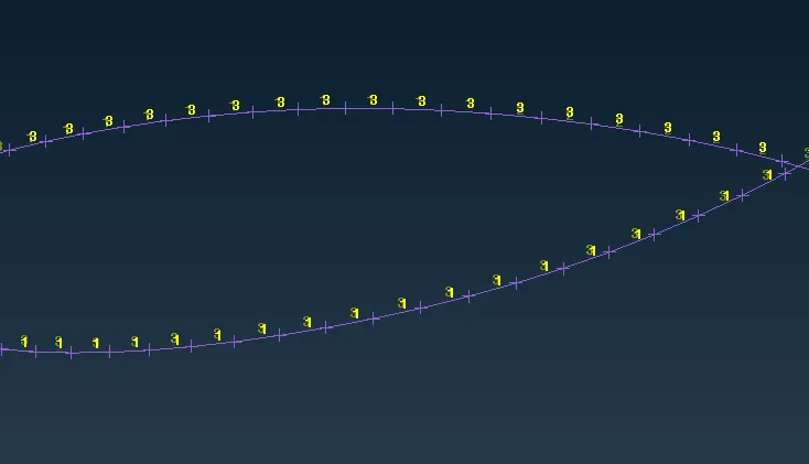
- Generate a middle curve for the spring. By using the middle option in the curves.
- Connect the curve into a single curve. By using the connect(multi) option in curves.
- Create a COG point for the curve to define the orientation.
- Select the CBAR element.
- Change the selection type to the curve box
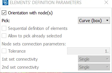
- Select the curve and give the middle mouse click.
- select the orientation node.
- specify the element length. In this case, The Element length is taken as 3 mm.
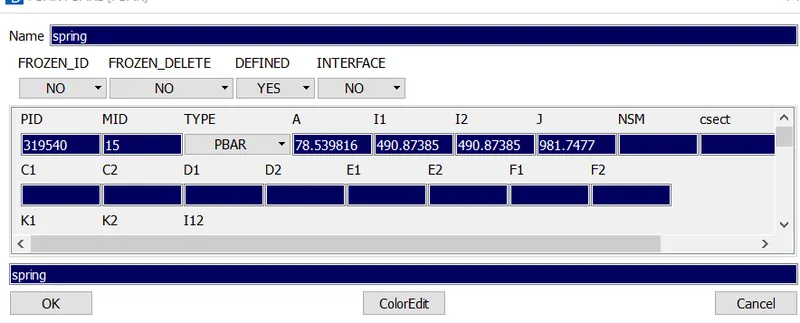
- After Specifying the element length as 3 mm, Do the middle mouse click and define a PID by creating a new PID.
- Define Area by giving Radius of spring. i.e. Cross-section radius of a spring.
SYMMETRICAL OPERATION
- Go to the Transform tab which is present on the right side of the Quality criteria tab. Then click Copy.
- Go for Entities selection mode and select the whole model surface except the top surface of the latch portion.
- It's recommended to hide the latch top surface before making the selection
- On a middle click confirmation, you can see a dialog box popping up from which you need to select the Symmetry tab.
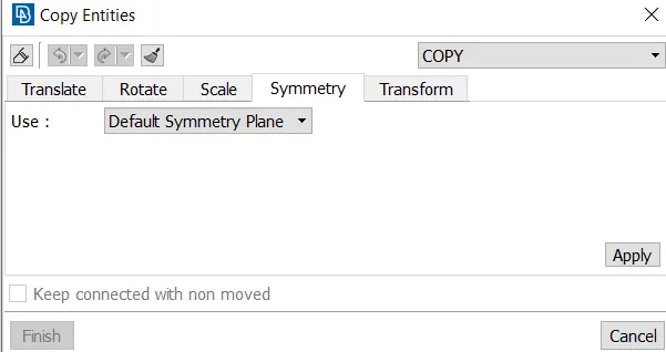
- Under the Symmetry tab, you can find various modes to carry out the symmetry operation.
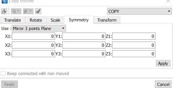
- Here I will be proceeding with the Mirror 3 points plane method.
- You can see the following dialog where you have to fill in the respective coordinate values.
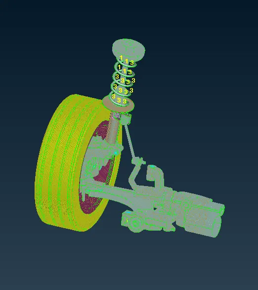
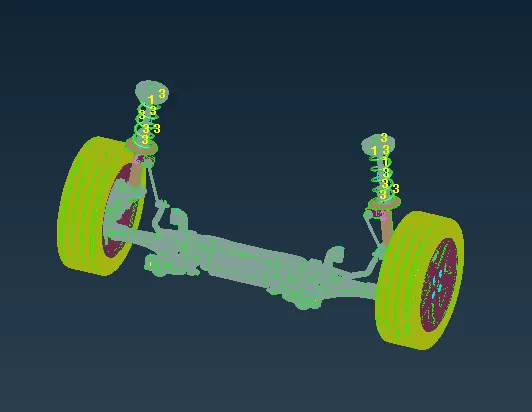
- Click Finish finally if the symmetry operation is performed correctly.
CONCLUTION
Thus the given Rear wheel component is meshed using a suitable method under given quality criteria and gives connections to it.