Meshing of Door Inner Panel
AIM :-
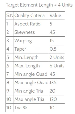
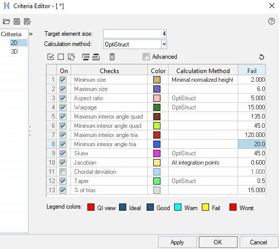
Follow the Quality Criteria and mesh the door inner panel component and assign thickness:
Target Element Length = 4mm
| S.N | Quality Criteria | Value |
| 1 | Aspect Ratio | 5 |
| 2 | Skewness | 45 |
| 3 | Warping | 15 |
| 4 | Taper | 0.5 |
| 5 | Min. Length | 2mm |
| 6 | Max. Length | 6mm |
| 7 | Min angle Quad | 45 |
| 8 | Max angle Quad | 135 |
| 9 | Min angle Tria | 20 |
| 10 | Max angle Tria | 120 |
| 10 | Tria % | 10 |
Method:
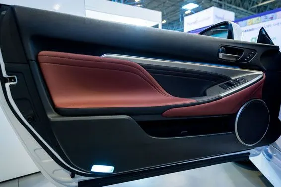
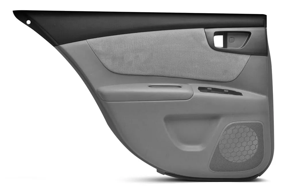
- A car door is a type of door, typically hinged, but sometimes attached by other mechanisms such as tracks, in front of an opening that is used for entering and exiting a vehicle. A vehicle door can be opened to provide access to the opening, or closed to secure it. These doors can be opened manually, or powered electronically.
- The exterior side of the door is designed of steel or other material like the rest of the vehicle's exterior. In addition, its decorative appearance, typically coloured with a design, is intended to match with the rest of the vehicle's exterior, the central purpose being to add to the overall aesthetic appeal of the vehicle exterior.
Geometry clean up:
- It is the first step in any pre-processing process. Performing geometry clean up means to remove all the double faces, unnecessary double and triple cons, removing the areas where the minimum length may fail, removing unnecessary fillets to simply the mesh.
- Below some images has been shown where unnecessary fillets have been removed. As these fillets are failing under minimum length criteria it is a better step to remove them and capture the surface more accurately.
Mid surfacing:
- To capture the mid surface thought auto mid option is there still manual mesh has been performed. This has been done in order to capture the feature more properly.
- As there are many ribs and some features which need to be captured properly manual mid has been taken.
- All the necessary steps which are required to take the mid for ribs are shown below.
Meshing:
- In order to mesh the component the criteria are given and it is necessary to mesh as per those criteria.
- A mesh is a network that is formed of cells and points. It can have almost any shape in any size and is used to solve Partial Differential Equations. Each cell of the mesh represents an individual solution of the equation which, when combined for the whole network, results in a solution for the entire mesh.
- Solving the entire object without dividing it into smaller pieces can be impossible because of the complexity that is within the object. Holes, corners and angles can make it extremely difficult for solvers to obtain a solution. Small cells, on the other hand, are comparably easy to solve and therefore the preferred strategy.
- The first step for numerically solving a set of partial differential equations (PDEs) is the discretization of the equations and the discretization of the problem domain. As mentioned earlier, solving the entire problem domain at once is impossible whereas solving multiple small pieces of the problem domain is perfectly fine. The equations discretization process is related to methods such as the Finite Difference Method, Finite Volume Method (FVM) and Finite Element Method, whose purpose is to make equations in continuous form and generate a system of algebraic difference equations. The domain discretization process generates a set of discrete cells and therefore points or nodes that cover the continuous problem domain.
- Meshing is an integral part of the engineering simulation process where complex geometries are divided into simple elements that can be used as discrete local approximations of the larger domain. The mesh influences the accuracy, convergence and speed of the simulation. Furthermore, since meshing typically consumes a significant portion of the time it takes to get simulation results, the better and more automated the meshing tools, the faster and more accurate the solution.
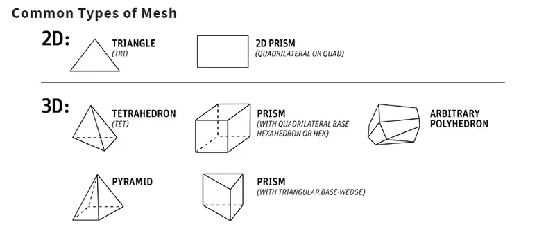
- Most physical phenomena can be solved using Partial Differential Equations (PDEs) but this is very difficult for most real-world problems. Any continuous object has infinite degrees of freedom (DOF) which makes it impossible to solve using hand calculations. So in FEM, we create a mesh that splits the domain into a discrete number of elements for which the solution can be calculated. The data is then interpolated across the whole domain.
- Mesh generation is the practice of creating a mesh, a subdivision of a continuous geometric space into discrete geometric and topological cells.
1. ASPECT RATIO
- This computes the ratio of the longest edge of an element (single element) to the shortest edge of the same element.
- In most cases, it is preferable to have an aspect ratio of 3 or 5. Meaning a ratio of 5:1 such that the longest side of an element doesn't cross more than 5x times that of the smallest side of the same element. An aspect ratio of 1 seems to be the most ideal. However, it cannot be achieved at each and every element.
2. WARPAGE
- It is the amount by which a mesh element or the element face deviates from being planar.
- For example, in the case of a quad, it can be calculated by splitting up it into two trias by constructing a diagonal between two opposite sides and finding the angle between these two tria planes. This quality criterion pertains to only quad elements with an element of warpage of 0 indicates it being perfectly planar.
3. SKEWNESS
- Skewness measures the angular deviation of the element from, as usual, being ideal. This parameter can be used to measure both tria and quad shell elements.
- For example, in a tria, it is calculated by finding the minimum angle between the vector from each node to the opposite mid-side AND another vector lying between two adjacent mid sides at each node of the element as shown below. Similarly, skew in quads are calculated by the angle formed between 2 lines joining the opposite mid-sides of a single element
Procedure :-
Step 1 :
Import the geometry in hypermesh and select optistruct profile.
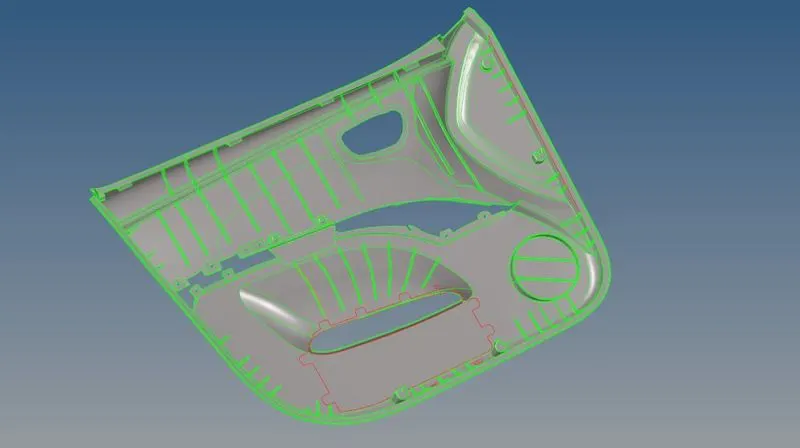
Cleanup the geometry. and toggle the lines and create a cunstruction line for convinent for extract the mid surface.
Before geometry cleanup criteria and parameters files has been defined.
Step 2 :
Next step is midsurface exraction.
Midsurface meshing is opted for components where the geometry thickness is small when compared with the span length of the components, so if you see most of the automotive structures are of sheet metal and plastics, where the length of the component is large when compared to the thickness, hence for this reason we opt for mid surface extraction and assign the thickness of the component to the elements through properties on components method.
Midsurface is extracted by selecting skin offset option for extraction.

Extracted surface is shown below:
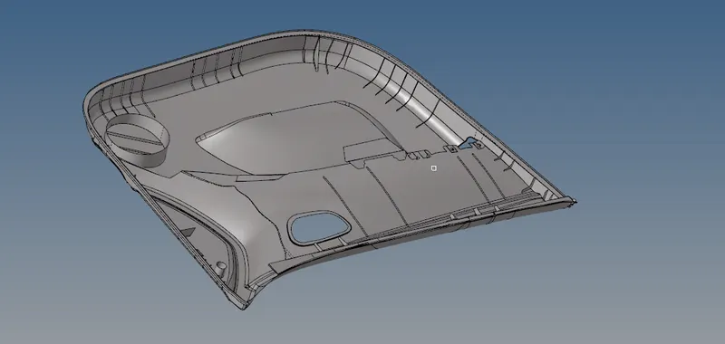
There is a gap between the surface. extend the ribs to lower mid surface edit > extend > lines > surface > etend
After extract the mid surface of the car side door model. create a construction lines on mid surface to convient for the doing mesh.
Step 3 :
Mesh Creation :-
Meshing is an integral part of the engineering simulation process where complex geometries are divided into simple elements that can be used as discrete local approximations of the larger domain. The mesh influences the accuracy, convergence and speed of the simulation.

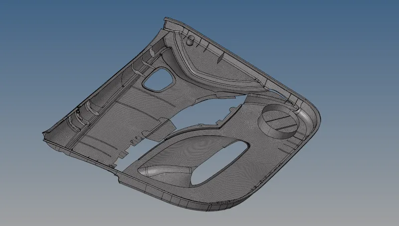
After meshing i wolud get some failed elements like maximum length, warpages and miximum angle elements clear all the failed elements and reduce tria concentratin in meshBelow mentioned pics shows the mesh at plaine surface and cornr surfacesdrag the tria elements as possible.
Failed elements is shown below:

As swe can see that there are 312 failed elemnts. Which can be improved by using cleanup tools.
After clering the geometry we can get the following elements.
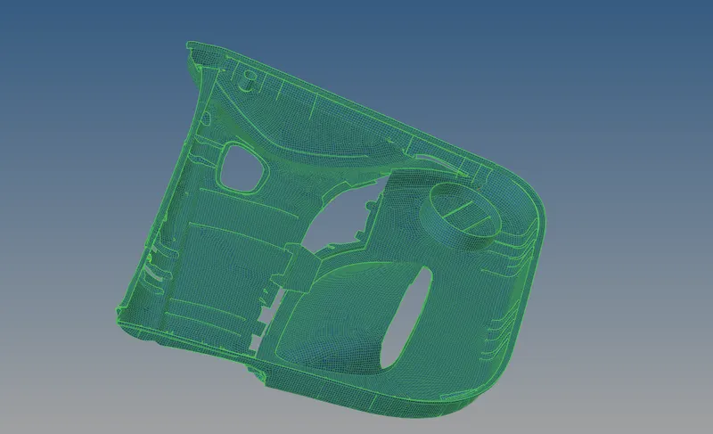
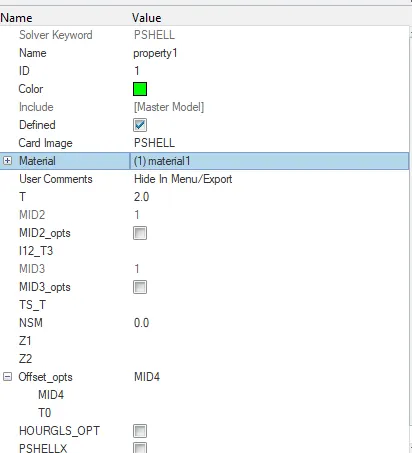
After that we have provided thickness of 2mm to component.
Insert the thickness value inside the property card for the component.
After that this property is assigned to the components.
--------------------------------------------------------------------------------------------------------------------------------------------------------
Conclusion :-
- The following components has been successfully meshed on the midsurface which has been extracted.
- The total number of elements formed for the side door panel were 33395 .