Project 2 - Measuring the distance of an object using ultrasonic sensor and also smoothen the sensor data using moving average filter
Overview of the Project:
In this project the implementation of code for “Measuring distance of an object using ultrasonic distance sensor (28015 Ping) and also smoothen the sensor data using moving average filter”.
Project Implementation:
To measure the distance of an object using ultra sonic sensor 28015 Ping we need an Arduino board and the sensor itself.
The sensor working is like, the ultra sound transmitter emits high frequency sound waves. The sound waves travel through the air medium and returns back after falling over any object in its path. The bounced back signal is cached at the receiver side of the sensor. The sensor will provide an output pulse to the host that will terminate when echo is detected, hence the width of the pulse is same as that of the distance to the target. Thus the distance is calculated. The sensor can detect objects with in a range of 2cm to 3meters. But the problem associated with the device is that it will et effected by the echo from the floor if the sensor is mounted low on our device. In addition to this the ping sensor cannot calculate the distance if the object is having the property of absorbing sound.
The sensor consists of 3 pins
1. Power(5v)
2. Ground(GND)
3. Signal(SIG)
The 5V pin and GND pin is used for power supply and grounding facility of the sensor. The terminal named SIG is used for both sending the trigger signal and the echo signal reception.
This senor can easily connected with Arduino board using tinkercad. Here the ultrasonic senor reads and writes the distance to the object in an LCD screen connected to the Arduino board.
Procedure:
1. Open Tinkercad
2. From the components select an Arduino UNO R3, a 16x2 I2C LCD and an PING sensor.
3. Connect the components using connection wire
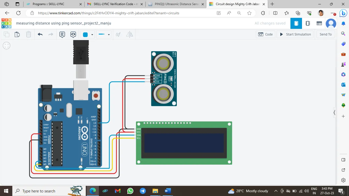
4. Connect the Ground and Vcc pins of Arduino , ultrasonic sensor and LCD together.
5. Then connect the analog input pins A4 and A5 of Arduino with the clock and data pins in the LCD SCA and SCL.
6. Now the transmitter and Receiver pins in the ultra-sonic sensor need to be connected with the digital out of Arduino. The SIG pin of the sensor is used for the transmission and reception of the signal. So connect it to the any of the digital out of the Arduino (here Digital PWM pin 13 in Arduino is used).
That’s all about the circuit arrangement and the schematic circuit arrangement is like figure 1 shown below.
Circuit setup:
For simulation we need to setup the code. For that choose code and select “blocks+text”
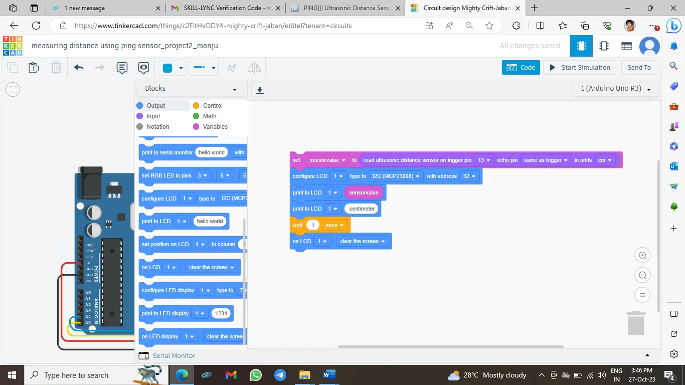
1. Create a variable named ‘sensorvalue’.
2. Under variables block, choose ‘set sensor value block’
3. Go to inputs, choose ‘read ultrasonic distance sensor on triger pin and eco pin ‘. Select the respective pin numbers on Arduino to which SIG pin connected
4. From output block, choose configure LCD
5. Then from the output block again, choose the ‘print to LCD’ and insert ‘sensorreading’ under variable block.
6. To view the unit of distance measured again choose ‘print to LCD’ from the output block and type “centimeters” as unit.
7. Then from control section insert a delay of second’.
8. Then clear the LCD screen using ‘on LCD clear the screen’ under output block
The screenshot for block is like figure 2 shown below:
Block code(screen shot):
The c++ code for the same is,
Code:
// C++ code
//
#include <Adafruit_LiquidCrystal.h> //header file for liquid crystal display
float sensorvalue = 0;//sensor value is declared as a global variable and initialized to 0
long readUltrasonicDistance(int triggerPin, int echoPin)//function to read value from ultra sonic sensor
{
pinMode(triggerPin, OUTPUT); // trigger pin is set as output pin
digitalWrite(triggerPin, LOW);//set state of trigger pin to low
delayMicroseconds(2);//small delay is given
// Sets the trigger pin to HIGH state for 10 microseconds
digitalWrite(triggerPin, HIGH);//trigger pin is set to high to emit sound waves to other object
delayMicroseconds(10);//a delay of 10 microseconds is given
digitalWrite(triggerPin, LOW);//again setting trigger pin to low to stop sending signals outside
pinMode(echoPin, INPUT);//eco pin set to input to receive signal from other devices
// Reads the echo pin, and returns the sound wave travel time in microseconds
return pulseIn(echoPin, HIGH);
}
Adafruit_LiquidCrystal lcd_1(0);
void setup() //setup function which starts when simulation begins
{
lcd_1.begin(16, 2);//function begin of object lcd_1 is called to setup the display to 16 coluns an 2 rows
}
void loop()//function named loop
{
sensorvalue = 0.01723 * readUltrasonicDistance(13, 13);//assigns value to sensor value by calling the function
lcd_1.print(sensorvalue);//print sensor value on lcd screen
lcd_1.print(" centimeter");//print on lcd screen
delay(1000); // Wait for 1000 millisecond(s)
lcd_1.clear();//to clear the lcd screen
}
Code explanation:
When we simulate the code, the function named setup () is runs first. This function runs only once when program starts. This initializes the settings of the devices in the circuit. The function named begin is called when control jumps inside the setup function. Ath that time the LCD is initialized with 16 columns and 2 rows.
After this the function named loop will get excecuted. It consists of the main logic of the program. The code inside the loop () function keeps on excecuting until the program stops.
The void loop() runs once simulation is started. This function does not take any parameters or return any value.
“sensorvalue = 0.01723 * readUltrasonicDistance(13, 13); “
This calls the function readUltrasonicDistance(13,13) by passing 13 and 13 as arguments.
This 13 is the pin number to which the SIG from the PING sensor is connected to the Arduino board. This function returns the time which the sound wave takes to travel and it is of type longint.
Inside the function the trigger pin is set to output pin so that it can send signals to sensor. Then by writing low to trigger clears any previous signal in the trigger pin. after that a 2 micro second delay is given to the sensor for the sensor to settle.
Then writing high to trigger pin, to tell the sensor to emit the ultrasonic signal towards the object and then pauses program for 10 micro seconds . with this 10 seconds the signal travels back to the sensor from the object. After that make the trigger pin low, this ends the pulse.
Then the echopin (here SIG) is set to input pin to receive electrical signal from other devices. Then if any echo signal from object comes it gets received.
Then the function pulsein returns the value of – low long a pulse lasts on a digital pin. the function takes two parameters high/low and echopin. This corresponds to the time value ie, how long it takes for the sound wave to travel from the transmitter and bounce back on to the receiver. This value in microseconds is stores and returned by the function. This is multipled with the 0.01723. The constant 0.01723 is the conversion factor which converts the microsecond value to centimeters. The result of the calculation is the distance value , which is stored in sensor value.
The distance value thus calculated is printed on the LCD screen using lcd_1.print(sensorreading);
Then a delay of few seconds is provided and the LCD screen is cleared.
After excecuting this the loop function ends and starts again from the beginning and repeats the process until program stops.
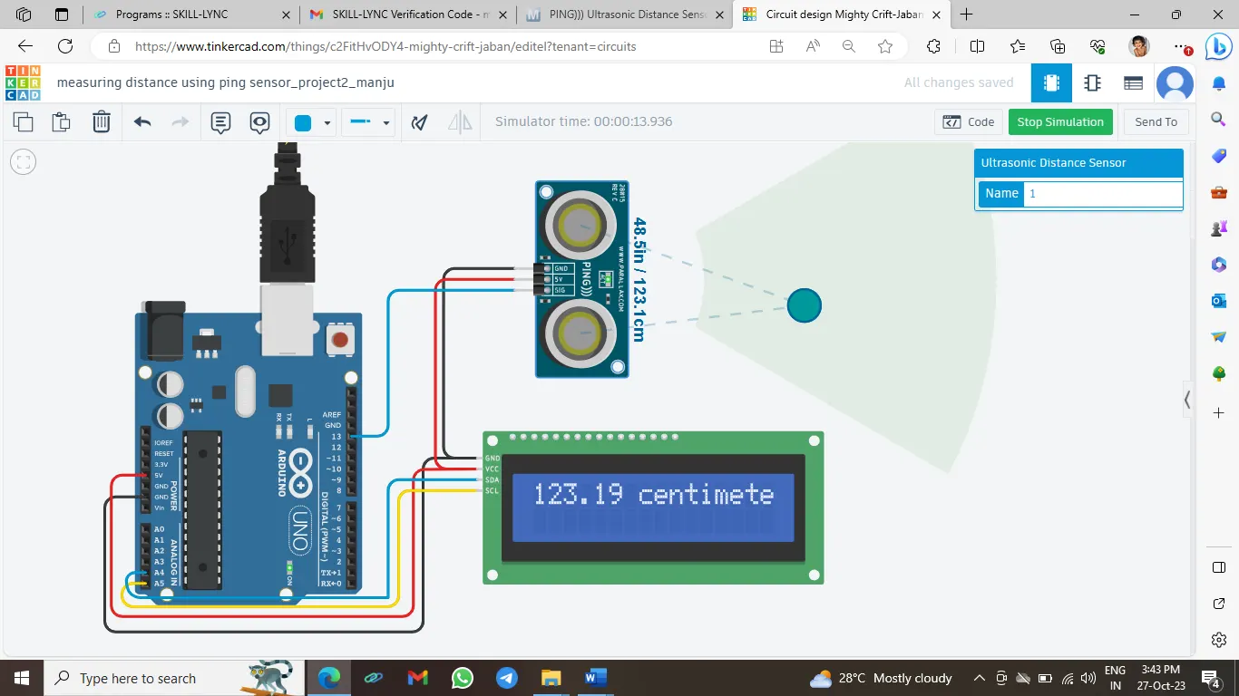
Output:
Conclusion:
This project implements the ultra sonic sensor with a moving average filter to measure the distance of an object. The moving average filter helps in reducing the noise signals. The same idea can be further expanded to implement parking sensor in vehicles.