Project 1 - Interfacing a 16*2 LCD with Arduino using I2C protocol
Project Question:
Interfacing a 16*2 LCD with Arduino using I2C protocol
Overview of the Project:
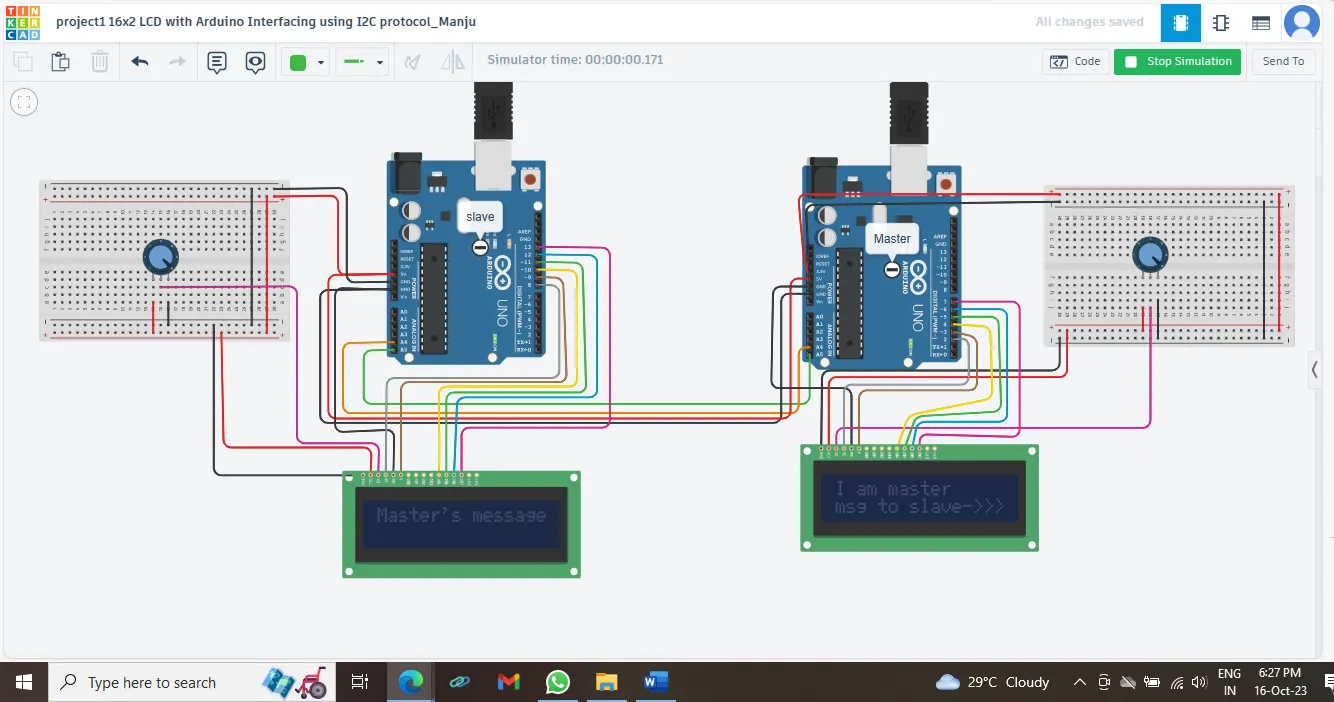
Here in this project I2C communication between master and slave is demonstrated. A message is send from the master Arduino board and it is received by the slave Arduino. The message send and the message received, both are displayed on an LCD interfaced with the Arduino boards.
I2C means inter integrated circuit protocol. This concept having multi slave and multi master and this is used for short distance communication somewhat inside the boards.
Procedure:
Open Tinkercad. Select to Arduino Boards,. Name one as master and other as slave. Both master and slave is connected to an LCD display.
The circuit components were, two Arduino Uno Boards(one for master and other for slave), 16x2 LCDs (one for master and other for slave), two potentiometers to adjust the contrast of LCD Display(10kilo ohms ),
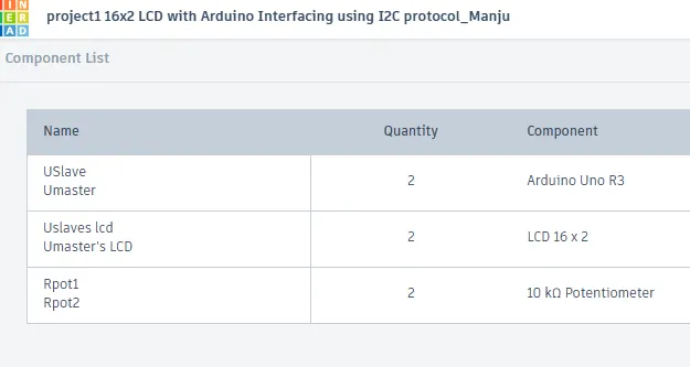
(figure 1 – list of components)
The circuit setup, both schematic view and diagrammatic view is as shown below in figure 2 and 3
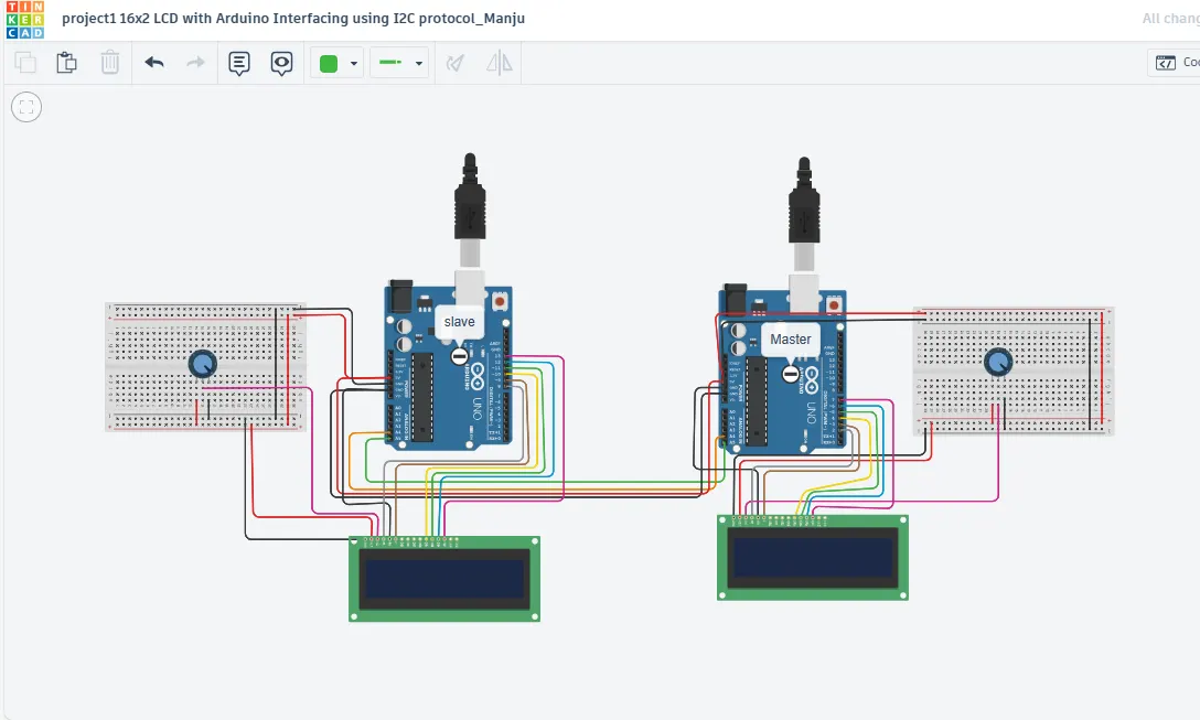
(the circuit diagram)
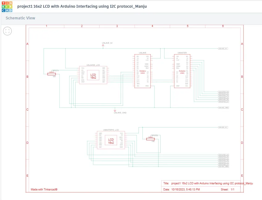
(the schematic view of the circuit)
Using the notes tool available in tinkercad both the master and slave Arduinos are marked for easy understanding there in the circuit diagram.
For I2C communication the SDA(serial data) pin of both Arduinos, ie the A5 pins are connected together. Similarly the A4 pins for SCL (serial clock) GND and 5v – these 4 pins are connected together. A 10kilo ohm potentiometer is connected with both LCDs connected with the master and slave to adjust the brightness of LCD. The middle pin of the potentiometer is connected to the contrast pin in in LCD.
In the master Arduino the Digital out pins 4,5,6,7 are connected with the DB4,DB5,DB6 and DB7 of the LCD respectively. The enable pin of the LCD is connected to the PWM 3 and Register select to the Digital out 2 of Arduino. Similary in the slave Arduino also.
The code for the Master is like,
#include
#include
LiquidCrystal lcd(2,3,4,5,6,7);//pins connected to LCD
void setup()
{
Serial.begin(9600);//function to setup serial communication at speed of 9600 bits per second
Wire.begin(8);//To begin I2C communication, which initialise wire library with address of 8
Wire.onRequest(send);//To call the send function when master request data
lcd.begin(16,2); //function to interface with 16x2 LCD display
}
void loop()
{
lcd.setCursor(0,0);//To set the cursor to the begining
lcd.print("I am master");//To display in LCD connected to master
lcd.setCursor(0,1);//To set the cursor to the next line
lcd.println("msg to slave->>>"); //message to display in LCD of master
}
void send()
{
char ch[25]="Master's message ";//the string that is needed to displayed in the slave arduino
Wire.write(ch);//the response message for the data request made by the master to slave
}
Here the setup() function is executed when the board is powered on, ie up on simulation. It then calls the serial. Begin to set up serial communication at a rate of 9600 bytes per second. Then the wire library with an address of 8 byte is initialized by wire. Begin(8). This facilitates the master board to communicate with all other devices with same bus.
Wire.onRequest(send) , this is to request a callback function when the master board receives a request for data from slave device.
lcd.begin(16,2)- this is to initialaize the LCD with 16 columns and 2 rows
The loop function is repeatedly excecuted after setup function. It calls lcd.setcursor(0,0) to move the cursor to the first column and first row of the lcd display. Then lcd. Print will print the text “i am master” on the lcd display. This is for the user convenience, so that for the user to understand which one is master and which one is slave. Then the cursor is moved to the second line by using the lcd.setcursor(0,1) . In the next line the message to slave is printer. Which demos the sample message send to the slave from the master to the user.
The send function is defined outside the loop. Inside send function there having the character array of 25 characters in which the string that is to be send to the slave board is assigned. It calls Wire.write(ch) to write the string to the I2C bus. This will send 25 bytes of data (one for each element of ch) to the slave board.
The slave code:
#include
#include
LiquidCrystal lcd(2,3,4,5,6,7);//pins connected to LCD
void setup()
{
Serial.begin(9600);//function to setup serial communication at speed of 9600 bits per second
Wire.begin(8);//To begin I2C communication, which initialise wire library with address of 8
Wire.onRequest(send);//To call the send function when master request data
lcd.begin(16,2); //function to interface with 16x2 LCD display
}
void loop()
{
lcd.setCursor(0,0);//To set the cursor to the begining
lcd.print("I am master");//To display in LCD connected to master
lcd.setCursor(0,1);//To set the cursor to the next line
lcd.println("msg to slave->>>"); //message to display in LCD of master
}
void send()
{
char ch[25]="Master's message ";//the string that is needed to displayed in the slave arduino
Wire.write(ch);//the response message for the data request made by the master to slave
}
Output: