Project 2 - Measuring distance of an object using ultrasonic sensor (HC-SR04)
Live Session Batch 5
AVR Project 2
Overview of the Project:
In this project, the implementation of code for “Measuring distance of an object using ultrasonic distance sensor (HC-SR04)
Goals:
- Measuring the distance of an object using Ultrasonic Distance Sensor (HC-SR04)
- Usage of Input Capture Mode
Key Highlights of the Project:
- Measuring the distance travelled by the wave to the object and gets bounced back from the object to sensor.
- Measuring Pulse width using Input Capture Mode
Deliverables of this project:
- The distance travelled by a wave to the object for which we want to measure the distance using Ultrasonic Distance Sensor (HC-SR04).
- Measuring Pulse width using Input Capture Mode of Timer 1
Expected Outcomes:
The students will get the Knowledge on Ultrasonic sensor (HC-SR04) to measure the distance travelled by wave to the object, the hardware connection of Atmega328p and HC-SR04 and how to use input capture mode of Timer1
Execution of Project
Ultrasonic Sensor :
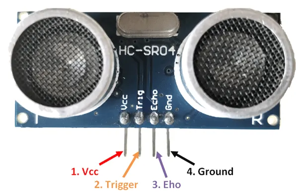
HC-SR04 Ultrasonic Sensor - Working
As shown above the HC-SR04 Ultrasonic (US) sensor is a 4 pin module, whose pin names are Vcc, Trigger, Echo and Ground respectively. This sensor is a very popular sensor used in many applications where measuring distance or sensing objects are required. The module has two eyes like projects in the front which forms the Ultrasonic transmitter and Receiver. The sensor works with the simple high school formula that
Distance = Speed × Time
The Ultrasonic transmitter transmits an ultrasonic wave, this wave travels in air and when it gets objected by any material it gets reflected back toward the sensor this reflected .
Input capture function modes inATmega328
The input capture function is used in many applications such as:
- Pulse width measurement
- Period measurement
- Capturing the time of an event
In AVR ATmega32, Timer1 can be used as an input capture to detect and measure events happening outside the microcontroller.
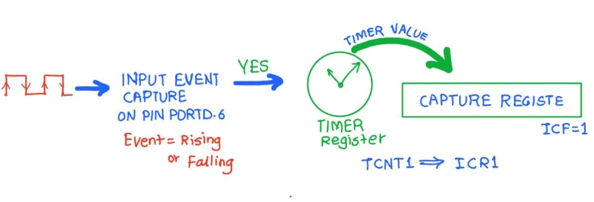
Upon detection of a defined event i.e. rising edge or falling edge on ICP pin (PORTD.6), the TCNT1(Timer / Counter register) value is loaded into the ICR1 (input capture) register and the ICF1 flag will get set.
Programming
To program, first, let us see TCCR1B (Timer Counter Control Register B)
TCCR1B: Timer Counter Control Register B

Bit 7 - ICNC1: Input Capture Noise canceller
Setting this bit activates the noise canceller. It causes a delay of 4 clock cycles as it considers a change only if it persists for at least 4 successive system clocks.
Bit 6 - ICES1: Input Capture Edge select
Select edge detection for input capture function.
0 = Capture on the falling edge
1 = Capture on rising edge
Bit 4: 3 - WGM13 : WGM12: Timer1 Mode select
These bits are used for mode selection like Normal mode, PWM mode, CTC mode, etc. here we will select normal mode, so set these bits to zero.
Bit 2: 0 - CS12: CS10:Timer1 Clock Select
|
CS02 |
CS01 |
CS00 |
Description |
|---|---|---|---|
|
0 |
0 |
0 |
No clock source (Timer / Counter stopped) |
|
0 |
0 |
1 |
clk (no pre-scaling) |
|
0 |
1 |
0 |
clk / 8 |
|
0 |
1 |
1 |
clk / 64 |
|
1 |
0 |
0 |
clk / 256 |
|
1 |
0 |
1 |
clk / 1024 |
|
1 |
1 |
0 |
External clock source on T0 pin. Clock on falling edge |
|
1 |
1 |
1 |
External clock source on T0 pin. Clock on rising edge. |
Steps tp Program :
- Initialize the TCCR1A and TCCR1B for proper timer mode (any mode other than 8, 10, 12, 14), to select the edge (Positive or Negative).
- Monitor the ICF1 flag in the TIFR register to see if the edge has arrived. Upon the arrival of the edge, the TCNT1 value is loaded into the ICR1 register automatically by the controller.
Program:
#include <avr/io.h> //AVR Preprocessor
#define F_CPU 16000000L //CPU Frequency
#include <util/delay.h> //Delay function
#define rs_high PORTD |=(1<<0);//DEFINE BIT FOR RS_HIGH
#define rs_low PORTD &=~(1<<0);//DEFINE BIT FOR RS_LOW
#define en_high PORTD |= (1<<2);//DEFINE BIT FOR EN_HIGH
#define en_low PORTD &=~(1<<2);//DEFINE BIT FOR EN_LOW
#define rw_high PORTD |= (1<<1);
#define rw_low PORTD &= ~(1<<1);
#define US_ERROR -1 //We're defining two more variables to know if the ultrasonic sensor is working or not
#define US_NO_OBSTACLE -2
#define US_PORT PORTC // We have connected the Ultrasonic sensor on port C. to use the ultrasonic we need two pins of the ultrasonic to be connected on port C
#define US_PIN PINC // We need to initialize the pin resistor when we want to take input.
#define US_DDR DDRC // We need data-direction-resistor (DDR) to set the direction of data flow. input or output. we will define it later, now we're just naming it.
#define US_TRIG_POS PC0 // The trigger pin of ultrasonic sound sensor is connected to port C pin 0
#define US_ECHO_POS PC1
int distance, previous_distance; //Variable declarations
void lcd_cmd(unsigned char cmd) //LCD command function
{
PORTB = cmd;
rs_low;
rw_high;
en_high;
_delay_ms(1);
en_low;
}
void lcd_data(unsigned char data)//LCD Data function
{
PORTB = data;
rw_low;
rs_high;
en_high;
_delay_ms(1);
en_low;
}
void lcd_init()//LCD Initialization
{
rw_high;
rs_high;
en_high;
PORTB = 0xff;
lcd_cmd(0x38);
_delay_ms(5);
lcd_cmd(0x02);
_delay_ms(5);
lcd_cmd(0x01);
_delay_ms(5);
lcd_cmd(0x0c);
_delay_ms(5);
lcd_cmd(0x06);
_delay_ms(5);
lcd_cmd(0x80);
_delay_ms(5);
}
void cursorpos(char x,char y)//Cursor position function
{
if((x<1 || x>2)||(y<1 || y>16))
{
x=1;
y=1;
}
if (x==1)
{
lcd_cmd(0x7F+y);
}
else
{
lcd_cmd(0xBF+y);
}
}
void lcd_out(char a, char b,char *str)//LCD function to passing string
{
cursorpos(a,b);
while(*str)
{
lcd_data(*str);
str++;
}
}
void lcd_clear()
{
lcd_cmd (0x01); //Clears the LCD screen
_delay_ms(2); // Waits for two milliseconds
lcd_cmd (0x80); //Sets the cursor to the row 1 column 1
}
void HCSR04Init()
{
// We're setting the trigger pin as output as it will generate ultrasonic sound wave
US_DDR|=(1<<US_TRIG_POS);
}
void HCSR04Trigger()
{ //Function to generate ultrasonic sound wave for 15 microseconds
//Send a 10uS pulse on trigger line
US_PORT|=(1<<US_TRIG_POS); //high
_delay_us(15); //wait 15uS
US_PORT&=~(1<<US_TRIG_POS); //low
}
uint16_t GetPulseWidth()
{
// This function will be used to measure the pulse duration. When the ultra sound echo back after hitting an object
// The microcontroller will read the pulse using the echo pin of the ultrasonic sensor connected to it.
uint32_t i,result;
// Section - 1: the following lines of code before the section - 2 is checking if the ultrasonic is working or not
// it check the echo pin for a certain amount of time. If there is no signal it means the sensor is not working or not connect properly
for(i=0;i<600000;i++)
{
if(!(US_PIN & (1<<US_ECHO_POS)))
continue; //Line is still low, so wait
else
break; //High edge detected, so break.
}
if(i==600000)
return US_ERROR; //Indicates time out
//High Edge Found
// Section -2 : This section is all about preparing the timer for counting the time of the pulse. Timers in microcontrllers is used for timimg operation
//Setup Timer1
TCCR1A=0X00;
TCCR1B=(1<<CS11); // This line sets the resolution of the timer. Maximum of how much value it should count.
TCNT1=0x00; // This line start the counter to start counting time
// Section -3 : This section checks weather the there is any object or not
for(i=0;i<600000;i++) // The 600000 value is used randomly to denote a very small amount of time, almost 40 miliseconds
{
if(US_PIN & (1<<US_ECHO_POS))
{
if(TCNT1 > 60000) break; else continue; // If the TCNT1 value gets higher than 60000 it means there is not object in the range of the sensor
}
else
break;
}
if(i==600000)
return US_NO_OBSTACLE; //Indicates time out
//Falling edge found
result=TCNT1; // microcontroller stores the the value of the counted pulse time in the TCNT1 register. So, we're returning this value to the
// main function for utilizing it later
//Stop Timer
TCCR1B=0x00;
if(result > 60000)
return US_NO_OBSTACLE; //No obstacle
else
return (result>>1);
}
int main()
{
lcd_init(); // We're initializing the LCD
char numberString[4]; // We re defining an array of character. It will be utilized later to store integer to be displayed on the LCD screen
while(1) {
uint16_t r;
_delay_ms(100); //Let the LCD Module start
//Set io port direction of sensor
HCSR04Init();
while(1)
{
//Send a trigger pulse
HCSR04Trigger(); // Calling the ultrasonic sound wave generator function
//Measure the width of pulse
r=GetPulseWidth(); // Getting the duration of the ultrasound took to echo back after hitting the object
//Handle Errors
if(r==US_ERROR) // If microcontroller doesn't get any pulse then it will set the US_ERROR variable to -1
// The following code will check if there is error then it will be displayed on the LCD screen
{
cursorpos(1, 1); //lcd_setCursor(column, row)
char j[10] = "Error!";
lcd_out(1,1,&j);
}
else
{
distance=(r*0.034/2.0); // This will give the distance in centimeters
char f[15]= "Distance = ";
lcd_out(1,0,&f);
itoa(distance, numberString, 10); // Distance is an integer number, we can not display integer directly on the LCD. this line converts integer into array of character
lcd_out(2,4,numberString);
char h[6] = " cm";
lcd_out(2,10,&h);
previous_distance = distance;
_delay_ms(30);
}
}
}
}
Simulation:
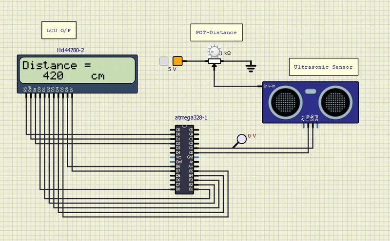
Result:
- Thus measured the distance travelled by a wave to the object using Ultrasonic Distance Sensor (HC-SR04).
- Measured Pulse width using Input Capture Mode of Timer 1