Project 1 - Controlling a DC motor using PWM and monitoring its Running status
Live Session Batch 5
Overview of the Project:
- Implement a system on the simulator for controlling a DC motor using L293 motor driver, monitor its status and print the running status of motor on the LCD Display.
Goals:
- Implement a system on simulator for Controlling the DC motor using L293 motor driver.
- Displaying the running status of DC motor on the LCD display.
Key Highlights of the Project:
- The DC motor can be controlled by using L293 motor driver.
- The speed of a DC motor can be controlled by varying its input voltage, for doing this is to use PWM (Pulse Width Modulation).
- L293D IC is a typical Motor Driver IC which allows the DC motor to drive on any direction.
Deliverables of this project:
- Implement the system for controlling DC motor.
- Controlling the speed of the DC motor using PMW.
- Displaying the present running status of DC machine on LCD display.
Expected Outcomes:
- Implement a system on simulator to control a DC motor using PMW
- Monitoring the running status of the DC motor using L293 motor driver which allows the DC motor to drive on any direction.
- Running status i.e. on which direction the DC motor is running is to be displayed on the LCD screen.
Implementation:
DC Motor:
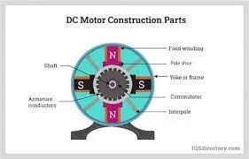
- A DC motor is defined as a class of electrical motors that convert direct current electrical energy into mechanical energy.
- When kept in a magnetic field, a current-carrying conductor gains torque and develops a tendency to move.
- Thus when electric fields and magnetic fields interact, a mechanical force arises.
- This is the principle on which the DC motors work.
L293 Motor Driver:
- L293d IC is known as a motor driver.
- It is a low voltage operating device like other ICs.
- The other ICs could have the same functions like L293d but they cannot provide the high voltage to the motor.
- L293d provides the continuous bidirectional Direct Current to the Motor.
- The Polarity of current can change at any time without affecting the whole IC or any other device in the circuit.
- L293d has an internal H-Bridge installed for two motors.
Pulse Width Modulation (PWM) is a technique by which the width of a pulse is varied while keeping the frequency constant.
Why do we need to do this? Let’s take an example of controlling DC motor speed, more the Pulse width more the speed. Also, there are applications like controlling light intensity by PWM.
A period of a pulse consists of an ON cycle (5V) and an OFF cycle (0V). The fraction for which the signal is ON over a period is known as the duty cycle.
Duty Cycle (In %) =
E.g. Consider a pulse with a period of 10ms which remains ON (high) for 2ms.The duty cycle of this pulse will be
D = 2ms / 10ms = 20%
Through the PWM technique, we can control the power delivered to the load by using the ON-OFF signal.
Pulse Width Modulated signals with different duty cycle are shown below
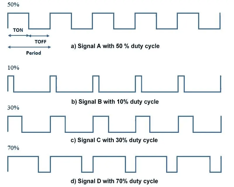
PWM Duty Cycle Waveforms
AVR Atmega PWM
Atmega has an inbuilt PWM unit. As we know, ATmega has 3 Timers T0, T1, and T2 which can be used for PWM generation. Mainly there are two modes in PWM.
- Fast PWM
- Phase correct PWM
We need to configure the Timer Register for generating PWM. PWM output will be generated on the corresponding Timer’s output compare pin (OCx).
PWM out Pins on AVR ATmega32
Configuring Timer0 for PWM generation
It is simple to configure PWM mode in Timer. We just need to set some bits in the TCCR0 register.
TCCR0: Timer Counter Control Register 0

Bit 7- FOC0: Force compare match
Write only bit, which can be used while generating a wave. Writing 1 to this bit will force the wave generator to act as if a compare match has occurred.
Bit 6, 3 - WGM00, WGM01: Waveform Generation Mode
|
WGM00 |
WGM01 |
Timer0 mode selection bit |
|---|---|---|
|
0 |
0 |
Normal |
|
0 |
1 |
CTC (Clear timer on Compare Match) |
|
1 |
0 |
PWM, Phase correct |
|
1 |
1 |
Fast PWM |
Bit 5:4 - COM01:00:
- When WGM00: WGM01= 11 i.e. Fast PWM. Compare Output Mode
waveform generator on OC0 pin
|
COM01 |
COM00 |
Mode Name |
Description |
|---|---|---|---|
|
0 |
0 |
Disconnected |
The normal port operation, OC0 disconnected |
|
0 |
1 |
Reserved |
Reserved |
|
1 |
0 |
Non-inverted |
Clear OC0 on compare match, set OC0 at TOP |
|
1 |
1 |
Inverted PWM |
Set OC0 on compare match, clear OC0 at TOP |
2. When WGM00: WGM01= 10 i.e. Phase correct PWM. Compare Output Mode
waveform generator on OC0 pin
|
COM01 |
COM00 |
Description |
|---|---|---|
|
0 |
0 |
The normal port operation, OC0 disconnected |
|
0 |
1 |
Reserved |
|
1 |
0 |
Clear OC0 on compare match when up-counting, set OC0 on compare match when down-counting |
|
1 |
1 |
Set OC0 on compare match when up-counting, Clear OC0 on compare match when down-counting |
Bit 2:0 - CS02:CS00: Clock Source Select
These bits are used to select a clock source. When CS02: CS00 = 000, then timer is stopped. As it gets a value between 001 to 101, it gets a clock source and starts as the timer.
|
CS02 |
CS01 |
CS00 |
Description |
|---|---|---|---|
|
0 |
0 |
0 |
No clock source (Timer / Counter stopped) |
|
0 |
0 |
1 |
clk (no pre-scaling) |
|
0 |
1 |
0 |
clk / 8 |
|
0 |
1 |
1 |
clk / 64 |
|
1 |
0 |
0 |
clk / 256 |
|
1 |
0 |
1 |
clk / 1024 |
|
1 |
1 |
0 |
External clock source on T0 pin. clock on falling edge |
|
1 |
1 |
1 |
External clock source on T0 pin. clock on rising edge. |
Setting Duty cycle: we have to load value in the OCR0 register to set the duty cycle.
255 value for 100% duty cycle and 0 for 0% duty cycle. Accordingly, if we load value 127 in OCR0, the Duty cycle will be 50%.
The advantage of using PWM mode in AVR is that it is an inbuilt hardware unit for waveform generation and once we set the PWM mode and duty cycle, this unit starts generating PWM and the controller can do other work.
Similarly, we can set PWM output on the other three OCx pins using Timer1 and Timer2.
PWM output is somehow close to the Analog output. We can use it as analog output for generating sine wave, audio signals, etc. it is also referred to as DDS.
Programme:
/*
* P1.c
*
* Created: 10/29/2022 3:03:41 PM
* Author : omjan
*/
#include <avr/io.h> //AVR Preprocessor I/o library
#define F_CPU 16000000ul //CPU Frequency
#include "avr/interrupt.h" //Interrupt library Function
#include <util/delay.h> //Delay Function
#define sw_dir (PIND&(1<<1)) //D1 pin enabled as switch button for motor direction control.
#define sw_spd (PIND&(1<<2)) //D2 pin enabled as switch button for motor speed control.
#define pw (PINC&(1<<3)) //C3 pin enabled as switch button for motor On/Off control.
#define lcd_port PORTB //PORTB set for LCD o/p
unsigned char i; //Variable declaration to increase duty cycle
#define RS_high PORTD|=(1<<5); //Pin5 used as RS High
#define RS_low PORTD&=~(1<<5);//Pin5 used as RS Low
#define EN_high PORTD|=(1<<6); //Pin6 enabled as High
#define EN_low PORTD&=~(1<<6);//Pin6 enabled as Low
void lcd_cmd(char cmd) //LCD command function
{
lcd_port=(cmd&0xf0); // Masking 4 bits for 4 bit LCD mode
RS_low;
EN_low;
_delay_ms(1);
EN_high;
lcd_port=((cmd<<4)&(0xf0));
RS_low;
EN_low;
_delay_ms(1);
EN_high;
}
void lcd_data(char data) //LCD function to send data
{
lcd_port=(data &0xf0);
RS_high;
EN_low;
_delay_ms(1);
EN_high;
lcd_port=((data<<4)&(0xf0));
RS_high;
EN_low;
_delay_ms(1);
EN_high;
}
void lcd_init()
{
lcd_cmd(0x02);_delay_ms(5);//Return the cursor to home
lcd_cmd(0x01);_delay_ms(5); //Clear screen
lcd_cmd(0x0C);_delay_ms(5);//Display ON cursor OFF
lcd_cmd(0x06);_delay_ms(5);//Increment cursor
lcd_cmd(0x80);_delay_ms(5);//Force cursor to begin 1st line
lcd_cmd(0x28);_delay_ms(5);//Used for 4 bits lcd mode
}
void cursorpos(char x, char y) //LCD cirsor positin fubction
{
if ((x<1||x>2)||(y>16||y<1)) // Execution if loop
{
x=1;
y=1;
}
if (x==1)
{
lcd_cmd(0x7f+y);
}
else
{
lcd_cmd(0xBF+y);
} }
void lcd_out(char x, char y, char *str) //LCD function to passing string
{
cursorpos(x,y);
while (*str)
{
lcd_data(*str);
str++;
} }
int main() //Main function
{
DDRB=0xFF; //Data directive register is enabled
DDRA|=((1<<0)|(1<<1)); //PORT 0 and 1 is enabled
DDRD&=~(1<<1); //PORT D1 is reset
DDRD&=~(1<<2);
DDRD|=(1<<5);
DDRD|=(1<<6);
DDRC&=~(1<<3);
PORTD|=(1<<2);
PORTC|=(1<<3);
i=64;
TCCR0=0X61;
GICR=(1<<INT0);
MCUCR=0X02;
sei();
lcd_init();
while (1)
{
while(pw==0)
{
if (sw_dir==0)
{
PORTA=0b00000001;
lcd_out(1,1,"Motor is Running");
lcd_out(2,3,"Clockwise");
}
else
{
PORTA=0b00000010;
lcd_out(1,1,"Motor is Running");
lcd_out(2,3,"Anticlockwise");
}
OCR0=i;
}
PORTA=0x00;
lcd_out(1,1,"Motor is Off");
lcd_out(2,3,"Caution !!!!!");
}
}
ISR(INT0_vect) //Interrupt service routine 0
{
i=i+20;
}
OUTPUT:
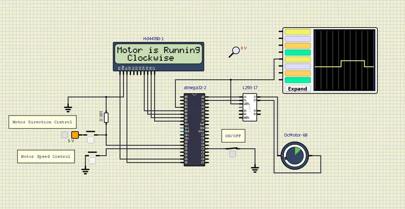
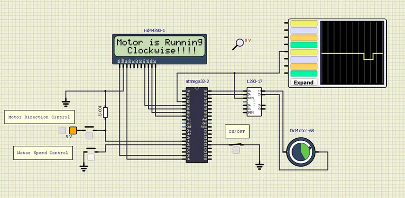
Motor turned ON/Running in Clockwise direction/Low Speed
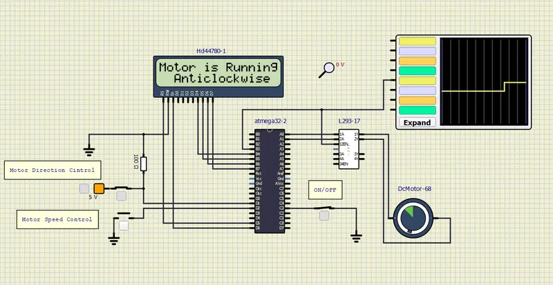
Motor turned ON/Running in Anticlockwise direction/Low Speed
Motor turned Off
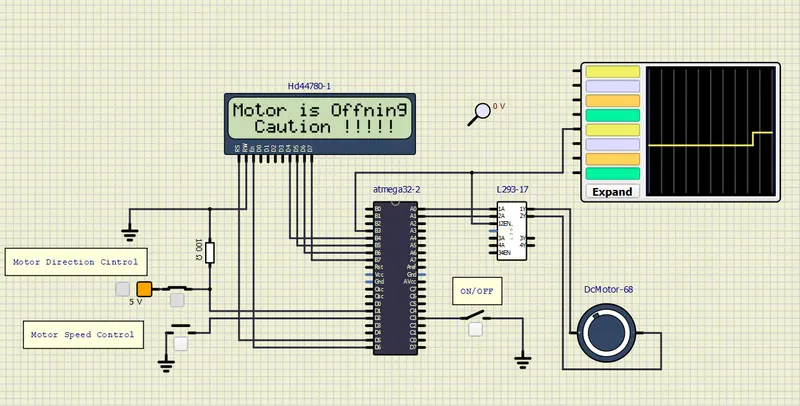
Motor turned ON/Running in Clockwise direction/High Speed
Reuslt:
- Thus implemented a system on simulator to control a DC motor using PMW.
- Monitoring the running status of the DC motor using L293 motor driver which allows the DC motor to drive on any direction.
- Running status i.e. on which direction the DC motor is running is to be displayed on the LCD screen.