Project 2 - Lane National Highway Roadway Design in Civil 3D
1Q.Creation of surface.
Ans: There are 2 ways for creation of Surface
Method-01(By xml)
- Create New File using Provided Template, For that click on File Then select New & setect templete ,click on ok.
- New File will be open then save the same file in Project Folder.
- For import land xml click on file select import xml & click on ok.
- After which we need to add a contour in the surface of propsector in tool bar by giving description.
- Then surface is created.
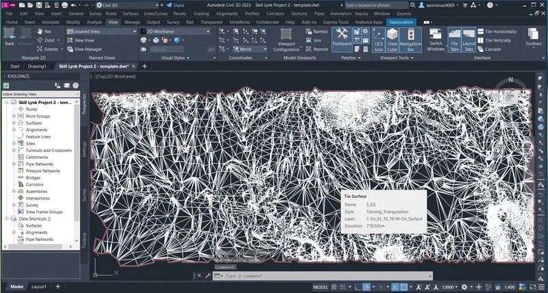
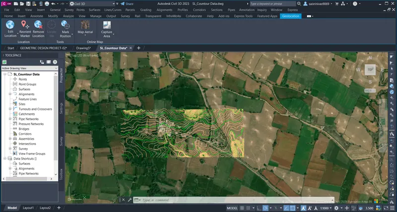
Method-02(By Using Contours)
- Create New File using Provided Template, For that click on File Then select New & setect templete ,click on ok.
- New File will be open then save the same file in Project Folder.
- Then contour will be pasted from cad at original co-ordinate.
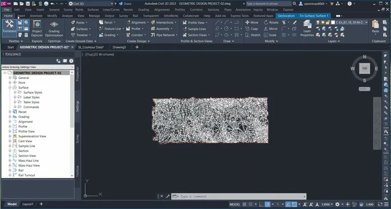
- After which we need to add a contour in the surface of propsector in tool bar by giving description.
- Then surface is created.
2Q.Alignment & profile design.
Ans: a)Alignment Creation
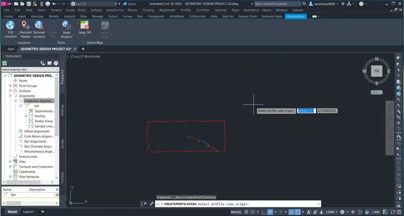
- After surface creation we need to create an alignment for which we need to on geolocation for this we have to set co-ordinate system & units setting then we can on map hybrid for alignment design
- Then the will be placed on exact location on map.
- We need see the given requirement for design.
- Then click on alignment present on to create it by layout.
- Then window opens we need to assign name and other description given.
- Then alignment layout tool is open after which we have fix straight line and add the horizontal curve and add transition length using given data.
- Try it different radius till it satisfy it.
- Then we have to create offset alignment again we need give it respect to centreline.
b) Pofile Creation
- After creating the alignment we need to propose profile for vertical section.
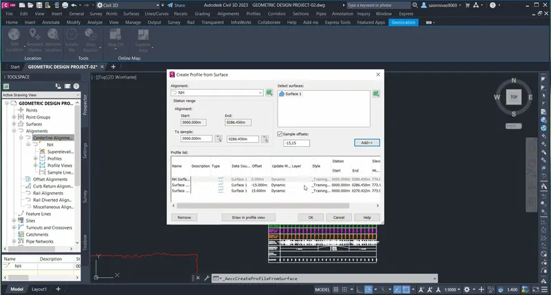
- Click on create profile then select the surface and put style then next a new window opens after which we need to select alignment and style click on next chainage range etc and its selected .
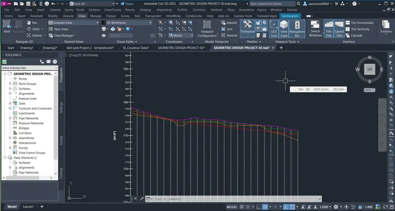
- Then select the band and some addition details are given as per required and then create a profile.
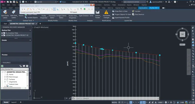
- Again click on create profile by layout for design profile and give the details present in popup window.
- Then we need to adjust using the edit tool so that some amount of cut fill can be equal.
- Then we need to give vertical curve and assign on design profile we need to change the properties of profile give the changes required and to be shown on the profile data then radius is adjusted as ‘k’ value required.
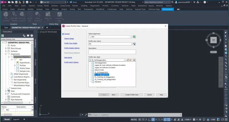
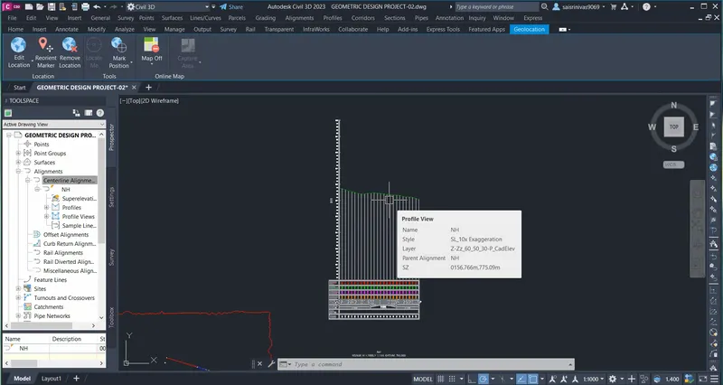
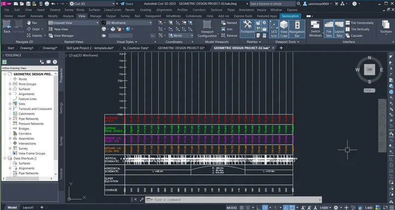
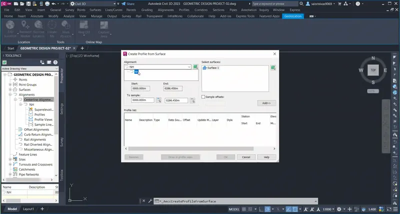
3Q.Creation of assembly & subassembly.
Ans:
- Click on corridor and then click on create assembly after name it and details style etc and click ok.
- Then we have create it on window and then we need to add subassemblies for tool pallet is going to be activated and then click on it.
- We can now add the lanes, shoulder and other parameters are added with the data provided and assuming the other data like thickness of pavement etc.
- Then we need assign the condition for road and for that we add from assembly then form junction then copy and paste on the shoulder side edit the slope as per requirement.
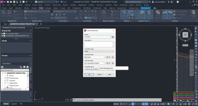
Assembly is created.
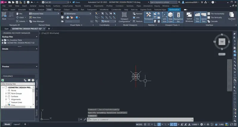
After the assembly creation All the sub assembly is done like GSB,WMM layers are to be drawn for given data.
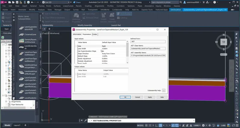
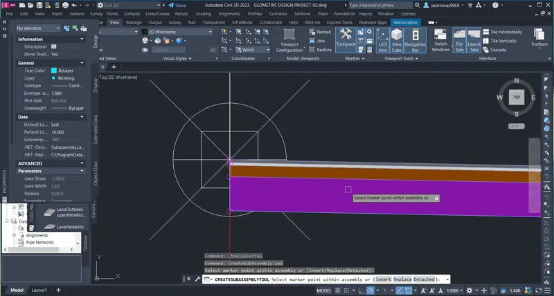
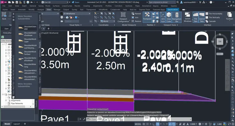
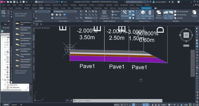
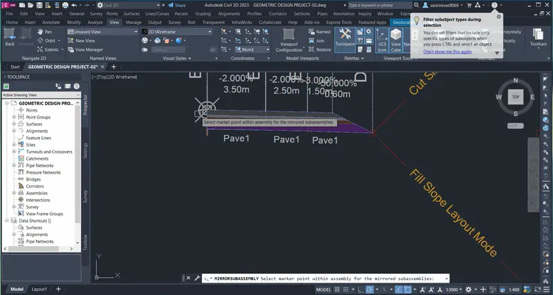
By using mirror option we get other side as it is.
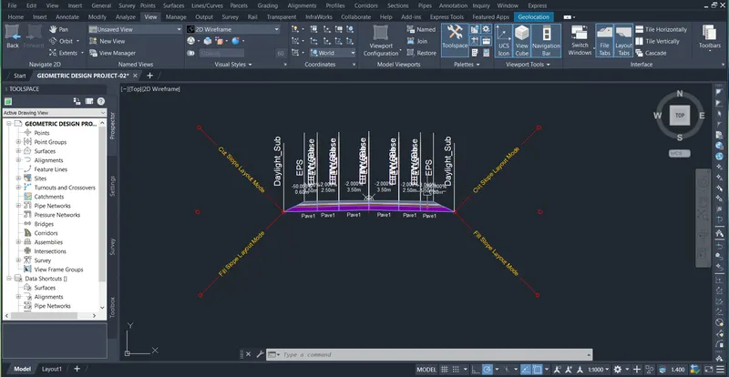
4Q.Corridor development.
Ans:
- Click on corridor on window to create it then name add the details required then create it on surface then add the parameters and frequency to apply assembly as required
- Then corridor surface is created for earthwork quantity by giving properties to it and add parameters and surfaces for top and bottom.
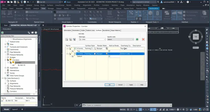
Corridor is created.
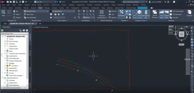
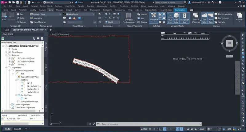
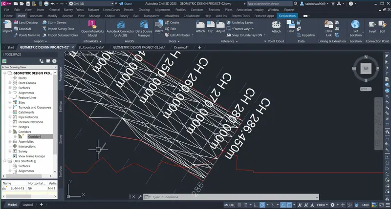
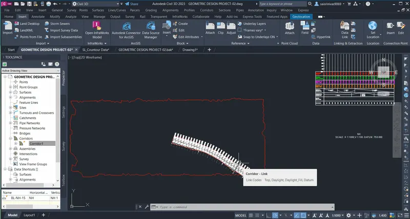
5Q.Section line & detail cross section.
Ans:
- For Cross-section we need create sample lines then we need to select alignment then create sample line group.
- Then using sample tool by taking range if chainage then we need to give width on both side of chainage
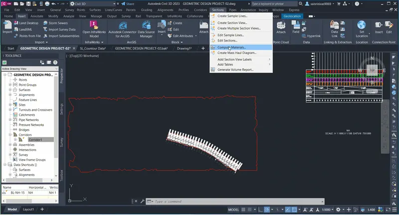
- Then to compute quantities we have compute material then we need add quantity take off criteria name the criteria.
- Again we approach compute material then materials list displayed then apply it click ok.
- Then we need to generate a report of cut fill volume for that click ok and put in excel.
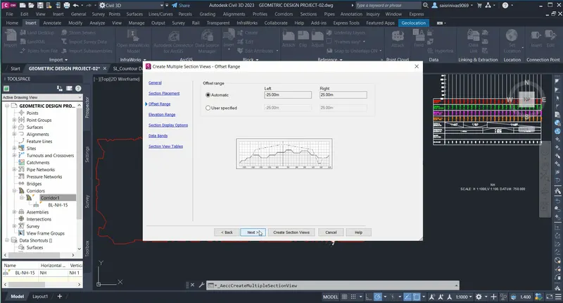
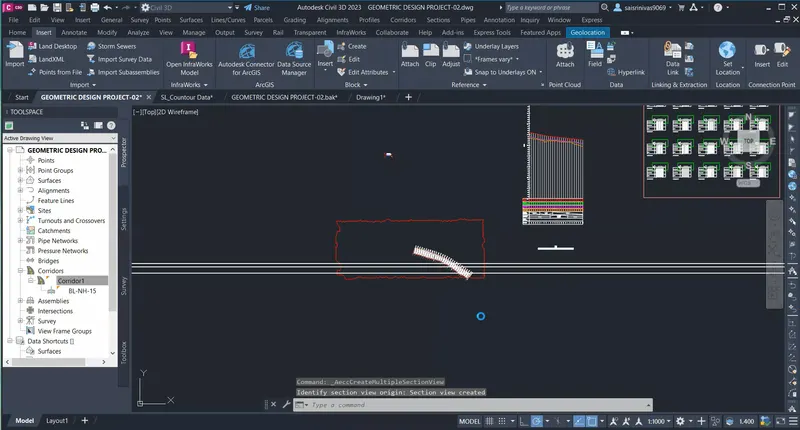
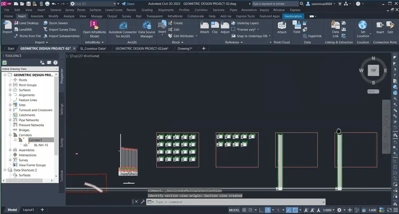
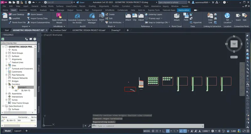
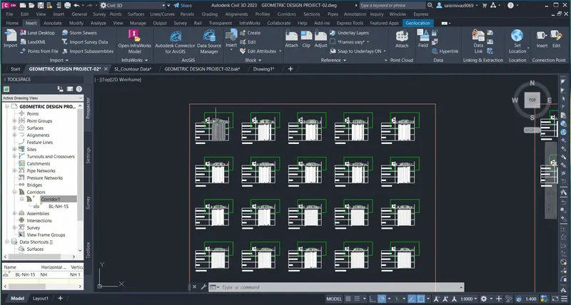
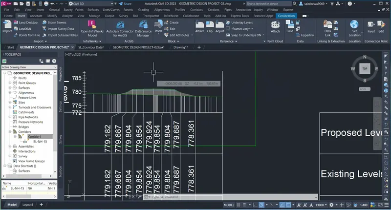
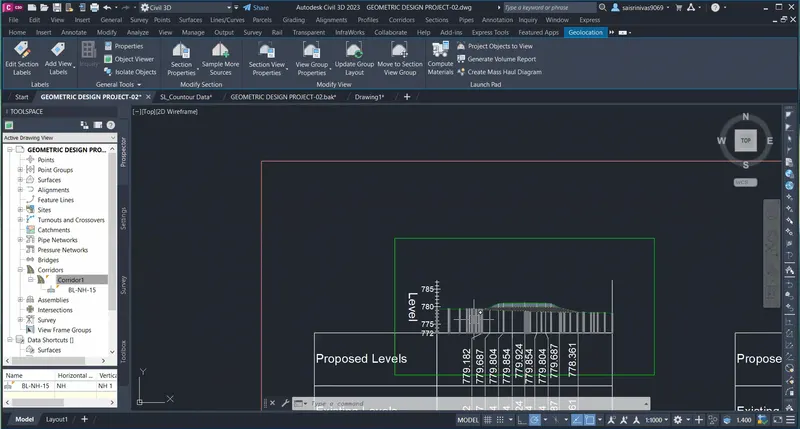
- Then for multiple section we need click on section select alignment, chainage etc is added then next other details are added and we have to create a section views.