Project 2-Highway Assistant-Lane Changing Assistant
Project Report: Highway Assistant – Lane Changing Assistant
1. Introduction to the Feature
The Highway Assistant is designed to assist drivers in monotonous driving conditions on highways by providing partial automation of the vehicle’s longitudinal and lateral guidance. It can automatically accelerate, brake, and steer the vehicle to a certain extent, although the driver must always remain vigilant and ready to take over control if needed.
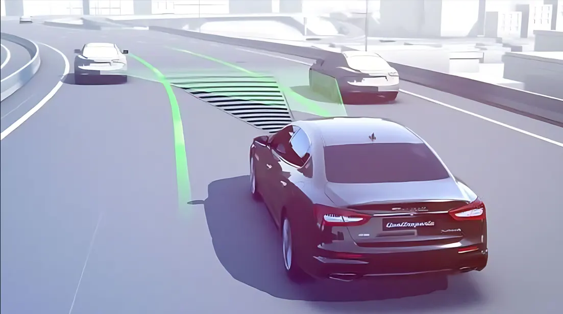
Lane-changing is one of the most dangerous maneuvers on highways due to blind spots that drivers cannot see using their mirrors. The Lane Changing Assistant helps reduce this risk by monitoring the area around and behind the vehicle. When a vehicle approaches quickly from behind or is in the driver’s blind spot, the system provides warnings, making lane changes safer. If the driver activates the turn signal despite a hazard, additional warnings are issued.
2. Basic Working Principle
The Highway Assistant operates at speeds up to 180 km/h (112 mph) and integrates two key technologies:
- Adaptive Cruise Control (ACC): Provides radar-based longitudinal guidance, controlling the vehicle’s speed and maintaining a safe distance from other vehicles.
- Lane Keeping Support: Uses video-based lateral guidance to keep the vehicle within the lane.
For lane changing, the system uses two mid-range radar sensors located in the rear bumper, which monitor traffic behind and beside the vehicle. These sensors provide data to software that compiles a comprehensive view of the traffic behind the vehicle. Based on this data, the system alerts the driver to potential hazards using visual, acoustic, and/or haptic signals, enhancing safety during lane changes.
3. Problem Statement
The objective of this project is to develop a specific requirement of the Highway Assistant’s Lane Changing Assistant algorithm. The full Highway Assistant algorithm is large and complex; this project focuses on implementing a small but critical part of the logic.
The goal is to develop the model in MATLAB Simulink following Model-Based Development (MBD) guidelines. The development process involves:
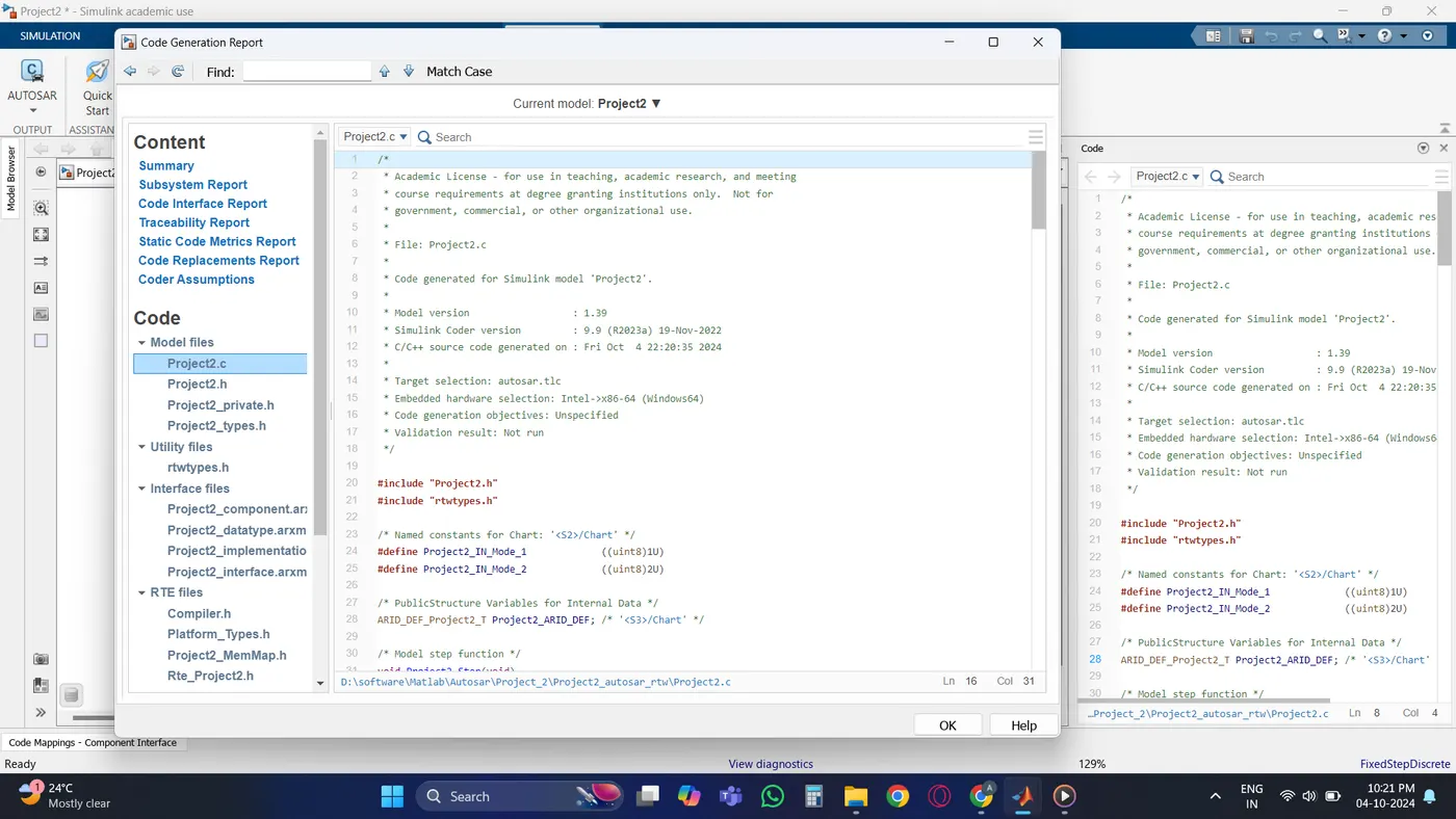
- Code Generation: Using Autosar Coder.
- Simulink Data Dictionary: Must be created and linked to the model.
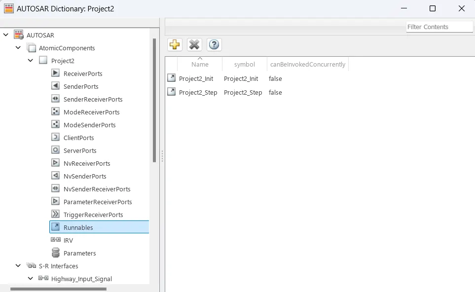
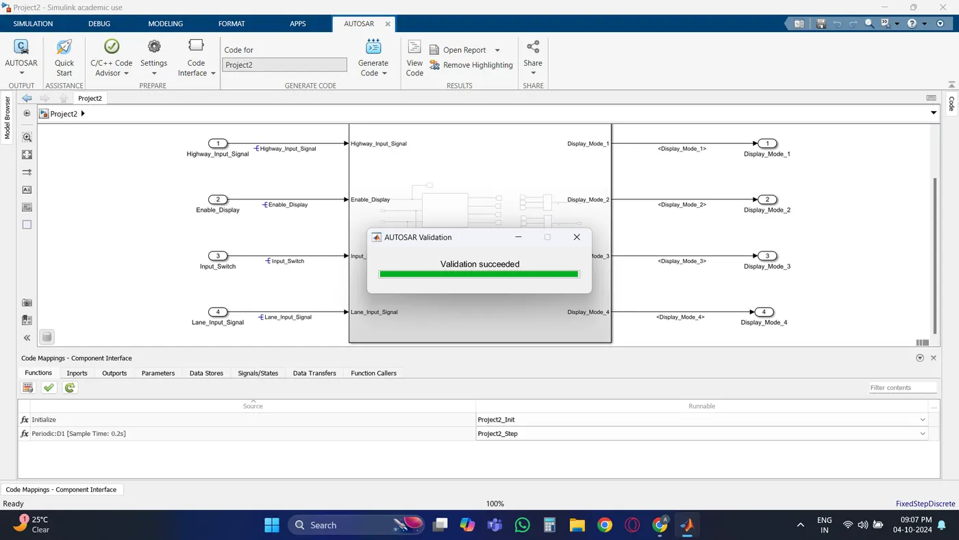
- Input & Output Signal Mapping: Signals must be mapped to the Autosar Editor.
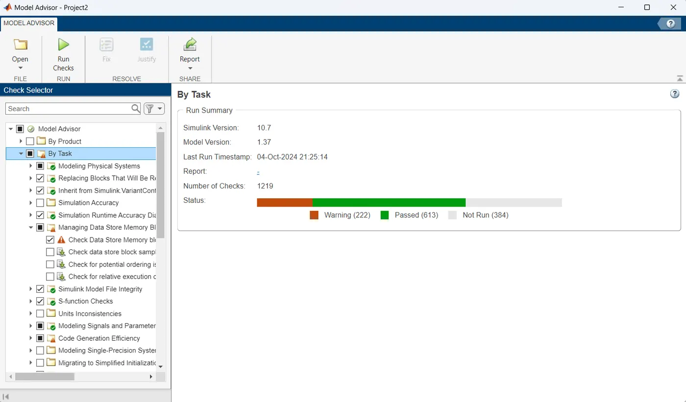
- Model Advisor Report: A mandatory step before code generation.
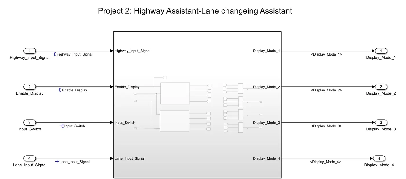
4. Simulink Model
5. Input Signals
The following input signals will be used in the model:
| Signal Name | Data Type | Range |
|---|---|---|
| Highway_Input_Signal | uint8 | 0–255 |
| Enable_Display | uint8 | 0–255 |
| Input_Switch | uint8 | 0–255 |
| Lane_Input_Signal | uint8 | 0–255 |
6. Local Signals
These signals are processed within the system:
| Signal Name | Data Type | Range |
|---|---|---|
| Highway_Display_Mode_1 | uint8 | 0–255 |
| Highway_Display_Mode_2 | uint8 | 0–255 |
| Highway_Display_Mode_3 | uint8 | 0–255 |
| Highway_Display_Mode_4 | uint8 | 0–255 |
| Lane_Display_Mode_1 | uint8 | 0–255 |
| Lane_Display_Mode_2 | uint8 | 0–255 |
| Lane_Display_Mode_3 | uint8 | 0–255 |
| Lane_Display_Mode_4 | uint8 | 0–255 |
7. Output Signals
The following output signals will be generated based on input conditions:
| Signal Name | Data Type | Range |
|---|---|---|
| Display_Mode_1 | uint8 | 0–255 |
| Display_Mode_2 | uint8 | 0–255 |
| Display_Mode_3 | uint8 | 0–255 |
| Display_Mode_4 | uint8 | 0–255 |
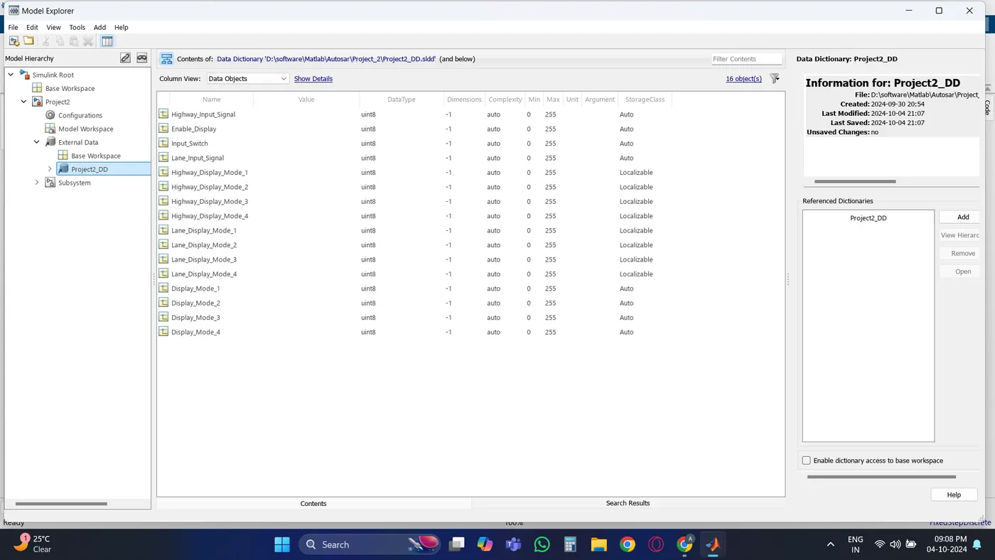
8. Simulink Data Dictionary
The all mention signals are added to data dictionary.
9. Requirements
9.1. Requirement No 1: Highway_DisplayUnit
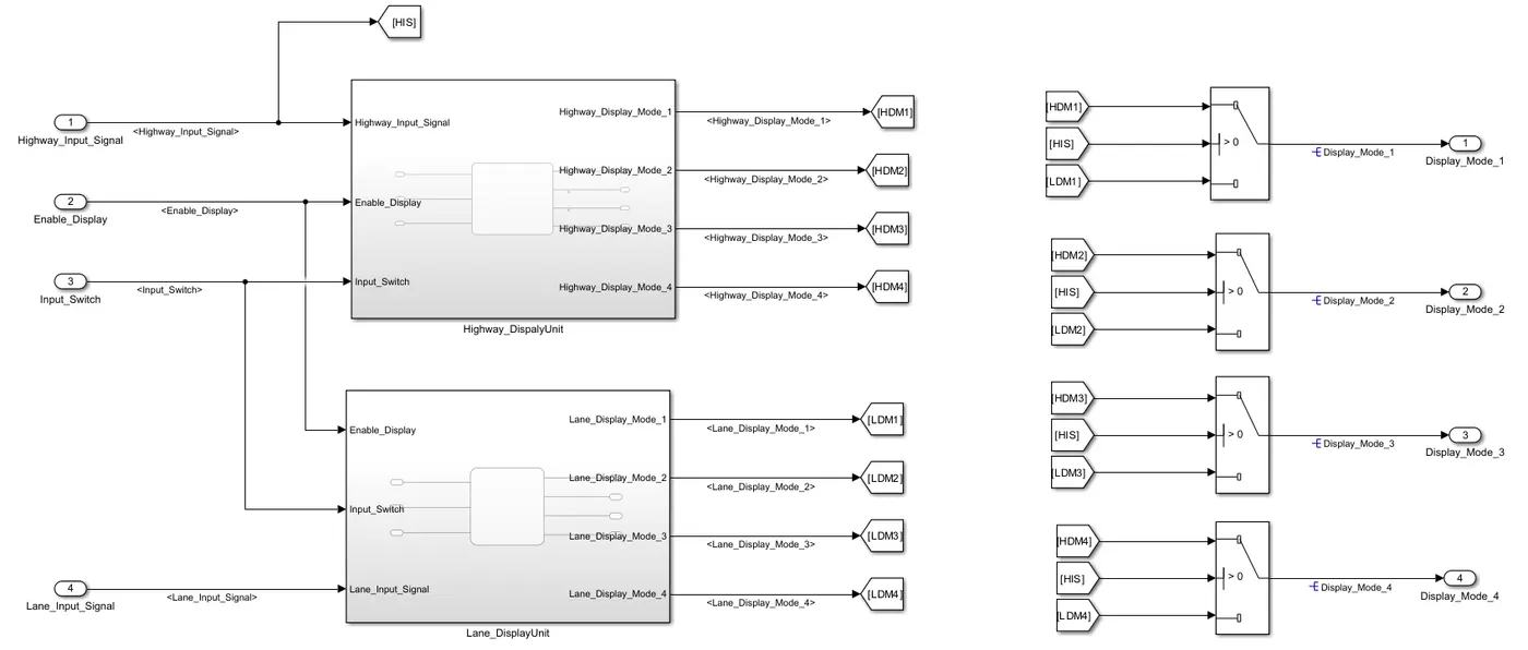
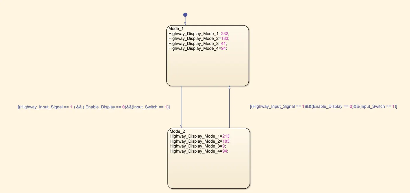
The Highway_DisplayUnit subsystem processes three input signals: Highway_Input_Signal, Enable_Display, and Input_Switch. These signals are assigned specific values to generate corresponding outputs. The output signals include Highway_Display_Mode_1, Highway_Display_Mode_2, Highway_Display_Mode_3, and Highway_Display_Mode_4.
Condition 1:
- Highway_Input_Signal = 1
- Enable_Display = off
- Input_Switch = on
Actions:
- Highway_Display_Mode_1 = 232
- Highway_Display_Mode_2 = 183
- Highway_Display_Mode_3 = 41
- Highway_Display_Mode_4 = 94
Condition 2:
- Highway_Input_Signal = 1
- Enable_Display = on
- Input_Switch = on
Actions:
- Highway_Display_Mode_1 = 213
- Highway_Display_Mode_2 = 183
- Highway_Display_Mode_3 = 9
- Highway_Display_Mode_4 = 94
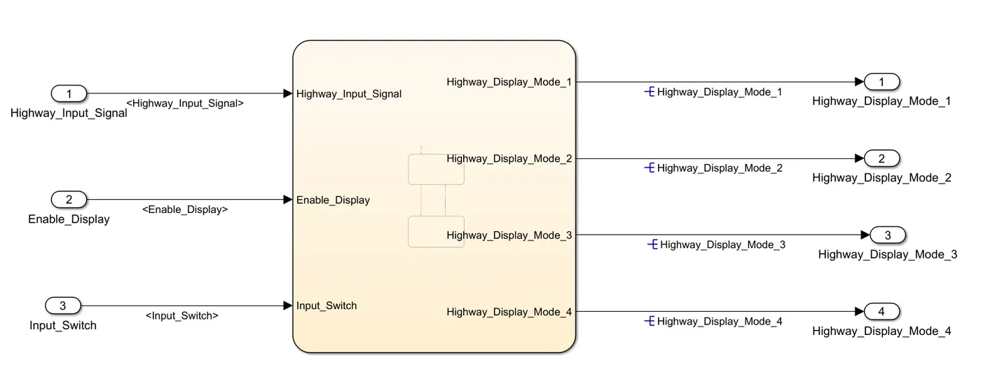
9.2. Requirement No 2: Lane_DisplayUnit
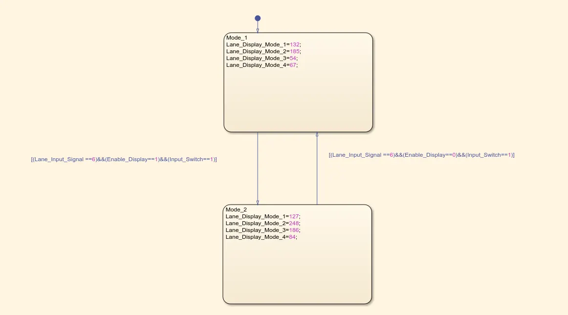
The Lane_DisplayUnit subsystem processes three input signals: Lane_Input_Signal, Enable_Display, and Input_Switch. These signals are assigned specific values to generate corresponding outputs. The output signals include Lane_Display_Mode_1, Lane_Display_Mode_2, Lane_Display_Mode_3, and Lane_Display_Mode_4.
Condition 1:
- Lane_Input_Signal = 6
- Enable_Display = off
- Input_Switch = on
Actions:
- Lane_Display_Mode_1 = 132
- Lane_Display_Mode_2 = 185
- Lane_Display_Mode_3 = 54
- Lane_Display_Mode_4 = 67
Condition 2:
- Lane_Input_Signal = 6
- Enable_Display = on
- Input_Switch = on
Actions:
- Lane_Display_Mode_1 = 127
- Lane_Display_Mode_2 = 248
- Lane_Display_Mode_3 = 186
- Lane_Display_Mode_4 = 84
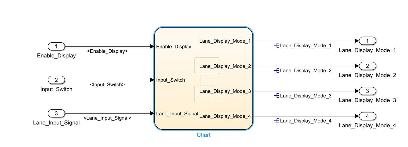
9.3. Requirement No 3: Combined Display Unit
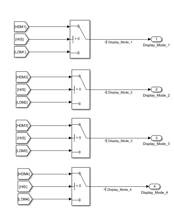
Signals from both the Highway_DisplayUnit and Lane_DisplayUnit are combined to form the final output. Each display mode (1 to 4) receives inputs from both subsystems and uses a switch block with Highway_Input_Signal to determine the final output.
- Display_Mode_1 = Highway_Display_Mode_1 or Lane_Display_Mode_1
- Display_Mode_2 = Highway_Display_Mode_2 or Lane_Display_Mode_2
- Display_Mode_3 = Highway_Display_Mode_3 or Lane_Display_Mode_3
- Display_Mode_4 = Highway_Display_Mode_4 or Lane_Display_Mode_4
10. Input & Output Signal Mapping
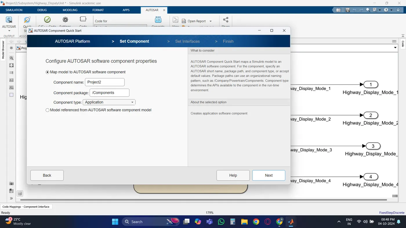
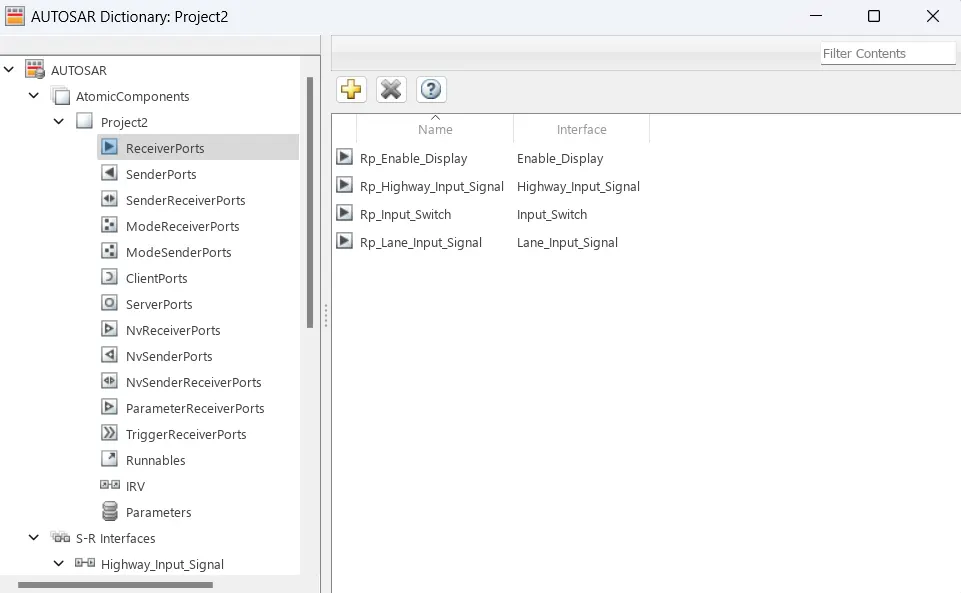
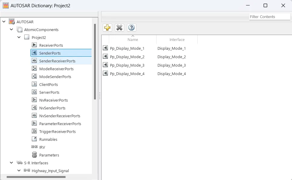
All input and output signals must be correctly mapped to the Autosar Editor to ensure they adhere to the Autosar standards and to facilitate accurate code generation. This ensures that the model can be smoothly integrated into the broader automotive software environment.
11. Model Advisor Report
Before proceeding to code generation, the model must pass a Model Advisor check. The Model Advisor Report is mandatory and ensures that the model follows industry standards and MBD guidelines, enhancing reliability and reducing errors in the code generation process.
12. Code
Project2.c
/*
* Academic License - for use in teaching, academic research, and meeting
* course requirements at degree granting institutions only. Not for
* government, commercial, or other organizational use.
*
* File: Project2.c
*
* Code generated for Simulink model 'Project2'.
*
* Model version : 1.39
* Simulink Coder version : 9.9 (R2023a) 19-Nov-2022
* C/C++ source code generated on : Fri Oct 4 22:20:35 2024
*
* Target selection: autosar.tlc
* Embedded hardware selection: Intel->x86-64 (Windows64)
* Code generation objectives: Unspecified
* Validation result: Not run
*/
#include "Project2.h"
#include "rtwtypes.h"
/* Named constants for Chart: '<S2>/Chart' */
#define Project2_IN_Mode_1 ((uint8)1U)
#define Project2_IN_Mode_2 ((uint8)2U)
/* PublicStructure Variables for Internal Data */
ARID_DEF_Project2_T Project2_ARID_DEF; /* '<S3>/Chart' */
/* Model step function */
void Project2_Step(void)
{
/* local block i/o variables */
uint8 Lane_Display_Mode_1;
uint8 Lane_Display_Mode_2;
uint8 Lane_Display_Mode_3;
uint8 Lane_Display_Mode_4;
uint8 Highway_Display_Mode_1;
uint8 Highway_Display_Mode_2;
uint8 Highway_Display_Mode_3;
uint8 Highway_Display_Mode_4;
sint32 tmp_0;
uint8 tmp;
/* Chart: '<S2>/Chart' incorporates:
* Inport: '<Root>/Enable_Display'
* Inport: '<Root>/Highway_Input_Signal'
* Inport: '<Root>/Input_Switch'
*/
if (Project2_ARID_DEF.is_active_c3_Project2 == 0U) {
Project2_ARID_DEF.is_active_c3_Project2 = 1U;
Project2_ARID_DEF.is_c3_Project2 = Project2_IN_Mode_1;
Highway_Display_Mode_1 = 232U;
Highway_Display_Mode_2 = 183U;
Highway_Display_Mode_3 = 41U;
Highway_Display_Mode_4 = 94U;
} else if (Project2_ARID_DEF.is_c3_Project2 == Project2_IN_Mode_1) {
if ((Rte_IRead_Project2_Step_Highway_Input_Signal_Highway_Input_Signal() ==
1) && (Rte_IRead_Project2_Step_Enable_Display_Enable_Display() == 0) &&
(Rte_IRead_Project2_Step_Input_Switch_Input_Switch() == 1)) {
Project2_ARID_DEF.is_c3_Project2 = Project2_IN_Mode_2;
Highway_Display_Mode_1 = 213U;
Highway_Display_Mode_2 = 183U;
Highway_Display_Mode_3 = 9U;
Highway_Display_Mode_4 = 94U;
} else {
Highway_Display_Mode_1 = 232U;
Highway_Display_Mode_2 = 183U;
Highway_Display_Mode_3 = 41U;
Highway_Display_Mode_4 = 94U;
}
/* case IN_Mode_2: */
} else if ((Rte_IRead_Project2_Step_Highway_Input_Signal_Highway_Input_Signal()
== 1) && (Rte_IRead_Project2_Step_Enable_Display_Enable_Display() ==
1) && (Rte_IRead_Project2_Step_Input_Switch_Input_Switch
() == 1)) {
Project2_ARID_DEF.is_c3_Project2 = Project2_IN_Mode_1;
Highway_Display_Mode_1 = 232U;
Highway_Display_Mode_2 = 183U;
Highway_Display_Mode_3 = 41U;
Highway_Display_Mode_4 = 94U;
} else {
Highway_Display_Mode_1 = 213U;
Highway_Display_Mode_2 = 183U;
Highway_Display_Mode_3 = 9U;
Highway_Display_Mode_4 = 94U;
}
/* End of Chart: '<S2>/Chart' */
/* Chart: '<S3>/Chart' incorporates:
* Inport: '<Root>/Enable_Display'
* Inport: '<Root>/Input_Switch'
* Inport: '<Root>/Lane_Input_Signal'
*/
if (Project2_ARID_DEF.is_active_c1_Project2 == 0U) {
Project2_ARID_DEF.is_active_c1_Project2 = 1U;
Project2_ARID_DEF.is_c1_Project2 = Project2_IN_Mode_1;
Lane_Display_Mode_1 = 132U;
Lane_Display_Mode_2 = 185U;
Lane_Display_Mode_3 = 54U;
Lane_Display_Mode_4 = 67U;
} else if (Project2_ARID_DEF.is_c1_Project2 == Project2_IN_Mode_1) {
if ((Rte_IRead_Project2_Step_Lane_Input_Signal_Lane_Input_Signal() == 6) &&
(Rte_IRead_Project2_Step_Enable_Display_Enable_Display() == 1) &&
(Rte_IRead_Project2_Step_Input_Switch_Input_Switch() == 1)) {
Project2_ARID_DEF.is_c1_Project2 = Project2_IN_Mode_2;
Lane_Display_Mode_1 = 127U;
Lane_Display_Mode_2 = 248U;
Lane_Display_Mode_3 = 186U;
Lane_Display_Mode_4 = 84U;
} else {
Lane_Display_Mode_1 = 132U;
Lane_Display_Mode_2 = 185U;
Lane_Display_Mode_3 = 54U;
Lane_Display_Mode_4 = 67U;
}
/* case IN_Mode_2: */
} else if ((Rte_IRead_Project2_Step_Lane_Input_Signal_Lane_Input_Signal() == 6)
&& (Rte_IRead_Project2_Step_Enable_Display_Enable_Display() == 0) &&
(Rte_IRead_Project2_Step_Input_Switch_Input_Switch() == 1)) {
Project2_ARID_DEF.is_c1_Project2 = Project2_IN_Mode_1;
Lane_Display_Mode_1 = 132U;
Lane_Display_Mode_2 = 185U;
Lane_Display_Mode_3 = 54U;
Lane_Display_Mode_4 = 67U;
} else {
Lane_Display_Mode_1 = 127U;
Lane_Display_Mode_2 = 248U;
Lane_Display_Mode_3 = 186U;
Lane_Display_Mode_4 = 84U;
}
/* End of Chart: '<S3>/Chart' */
/* Switch: '<S1>/Switch' incorporates:
* Inport: '<Root>/Highway_Input_Signal'
* Switch: '<S1>/Switch1'
* Switch: '<S1>/Switch2'
* Switch: '<S1>/Switch3'
*/
tmp_0 = Rte_IRead_Project2_Step_Highway_Input_Signal_Highway_Input_Signal();
if (tmp_0 > 0) {
tmp = Highway_Display_Mode_1;
} else {
tmp = Lane_Display_Mode_1;
}
/* Outport: '<Root>/Display_Mode_1' incorporates:
* Switch: '<S1>/Switch'
*/
Rte_IWrite_Project2_Step_Display_Mode_1_Display_Mode_1(tmp);
/* Switch: '<S1>/Switch1' */
if (tmp_0 > 0) {
tmp = 183U;
} else {
tmp = Lane_Display_Mode_2;
}
/* Outport: '<Root>/Display_Mode_2' incorporates:
* Switch: '<S1>/Switch1'
*/
Rte_IWrite_Project2_Step_Display_Mode_2_Display_Mode_2(tmp);
/* Switch: '<S1>/Switch2' */
if (tmp_0 > 0) {
tmp = Highway_Display_Mode_3;
} else {
tmp = Lane_Display_Mode_3;
}
/* Outport: '<Root>/Display_Mode_3' incorporates:
* Switch: '<S1>/Switch2'
*/
Rte_IWrite_Project2_Step_Display_Mode_3_Display_Mode_3(tmp);
/* Switch: '<S1>/Switch3' */
if (tmp_0 > 0) {
tmp = 94U;
} else {
tmp = Lane_Display_Mode_4;
}
/* Outport: '<Root>/Display_Mode_4' incorporates:
* Switch: '<S1>/Switch3'
*/
Rte_IWrite_Project2_Step_Display_Mode_4_Display_Mode_4(tmp);
}
/* Model initialize function */
void Project2_Init(void)
{
/* (no initialization code required) */
}
/*
* File trailer for generated code.
*
* [EOF]
*/
D:\software\Matlab\Autosar\Project_2\Project2_autosar_rtw\Project2.c
Ln196Col20
has popup
13. Conclusion
The Highway Assistant – Lane Changing Assistant algorithm provides a crucial safety feature for highway driving by monitoring the vehicle’s blind spots and alerting the driver to potential hazards during lane changes. This project focuses on developing specific requirements of the system using MATLAB Simulink, following Autosar Coder guidelines for Model-Based Development. Through the use of input and output signal mapping, the system delivers real-time alerts to ensure safer driving conditions on highways.