Project 1 (Mini Project on Vehicle Direction Detection
Project: Vehicle Direction Determination
Aim: Develop a MATLAB Simulink model to determine the direction of a vehicle based on camera input.
Description: The system compares the yaw rate of the steering wheel with predefined angular values for left turn, right turn, and straight drive. It also considers input from a camera to detect road signs. By using switch and logical operator blocks, the system determines the vehicle's direction and provides a direction indicator.
Model: The MATLAB Simulink model consists of two subsystems: one for steering wheel input comparison and another for road sign comparison.
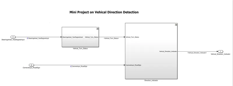
Requirement 1:
- Steering wheel input as yaw rate (Signal name: SteeringWheel_YawDegreeInput) is the input for this system.
- This is compared against 3 angular values, one each for left turn, right turn & straight drive (Calibration Values: Right_Turn_AngularLimit, Left_Turn_AngularLimit, Straight_Drive_Steering_Angle) to say which specific direction the steering wheel is turning towards.
- Use switch blocks to compare & develop this requirement. Keep this requirement in a subsystem & output of this requirement is a local signal (Signal Name: Vehicle_Turn_Status).
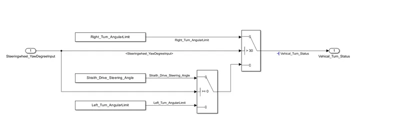
Execution:
In Requirment 1 SteeringWheel_YawDegreeInput is compeard with all three Calibration values. In first switch block if the input value id greter thea 30, then output Vehicle_Turn_Status is become 30. If the input value is equal to zero then the switch 2 is get active and the Vehicle_Turn_Status value is become 0.
Requirement 2:
- Keep this requirement as a separate subsystem. Inputs to this requirement are local signal from requirement 1 (Signal Name: Vehicle_Turn_Status) & an input signal from camera (Signal Name: CameraInput_RoadSign), which confirms the occurrence of a road sign.
- Signal Vehicle_Turn_Status is compared against calibration values (Calibration Values: RightTurn_RoadSign, LeftTurn_RoadSign, Straight_RoadSign), if each of them is found equal, then each of the three corresponding output is compared against the camera input signal,
- Using a logical operator block, only one among them is finally given as output signal (Signal Name: Vehicle_Direction_Indicator).
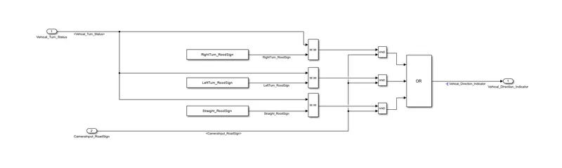
Execution:
In Requirment 2 Vehicle_Turn_Status value is compeard with all three Calibration values. After that the value is compaired with camera input signal using AND Gate. So here if both input signels is High the AND gate give the output signal High. Using OR gate we transfer that signal to the output.
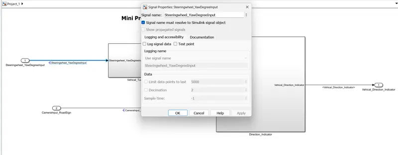
Signal Propogation :-
Requirement Taging :
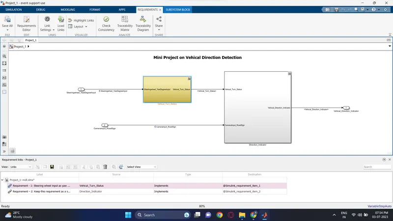
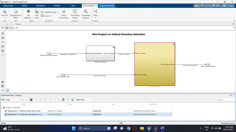
SLDD creation:
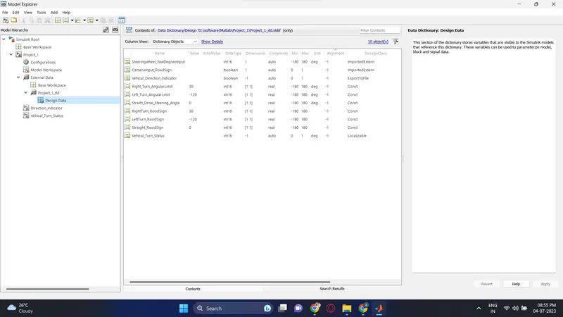
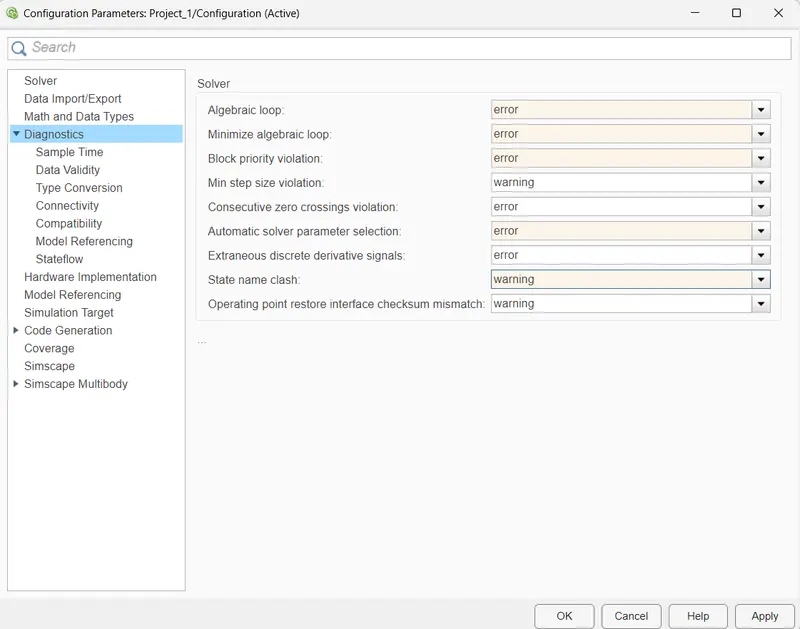
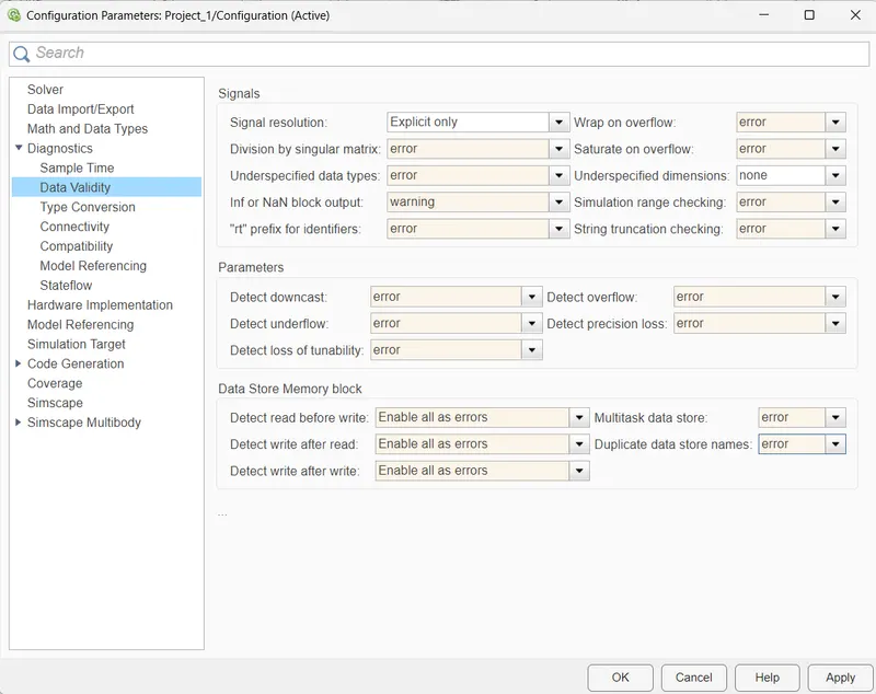
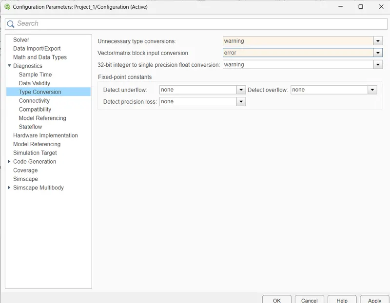
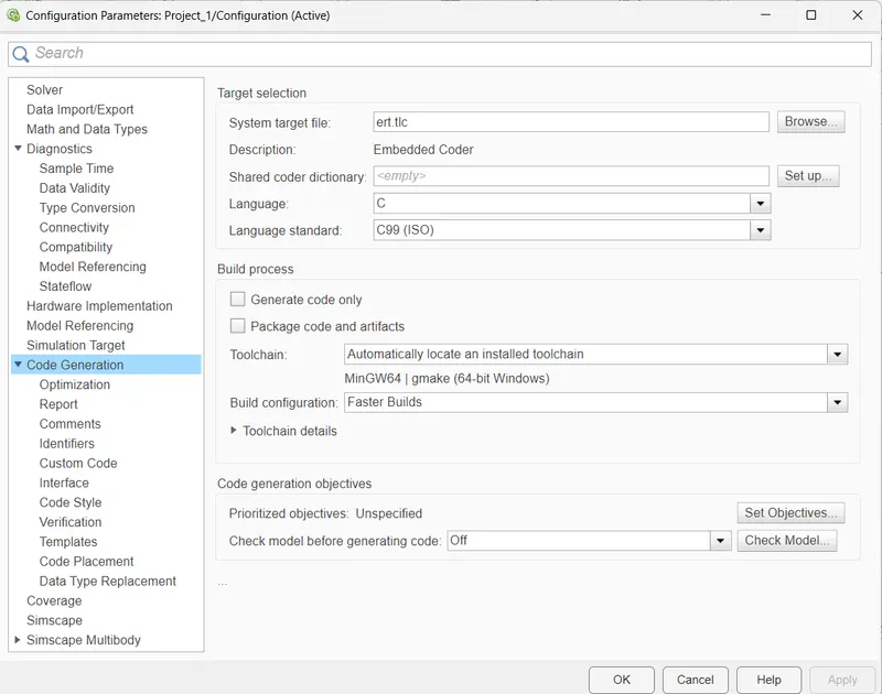
Model Settings:
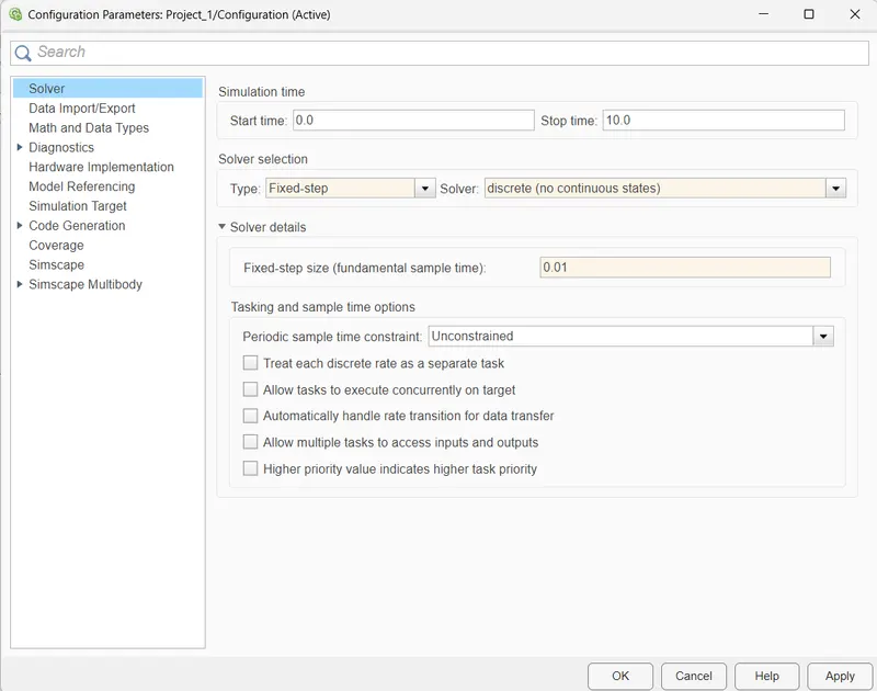
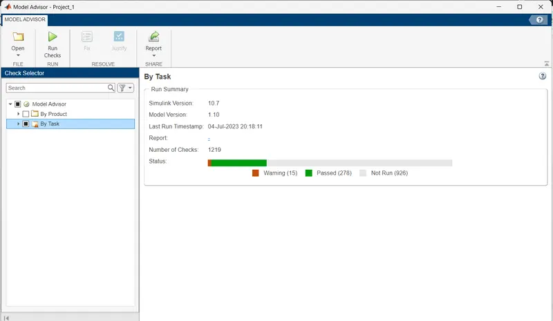
Model Advisor Report Ganeration:
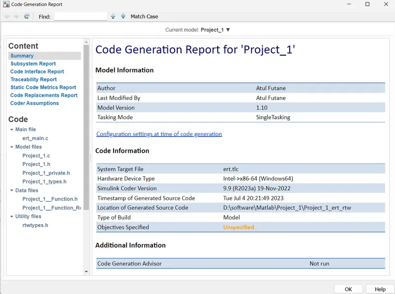
Code Ganeration Report:
Code :-
Result: The developed model accurately determines the vehicle's direction based on camera input and steering wheel yaw rate. It can be integrated with other driver assistance features and enhance overall driving safety.