Project 2-Highway Assistant-Lane Changing Assistant
ANS:-
Highway Assistant – Lane Changing Assistant
1.Aim:-
Model Development of a feature of Highway Assistant-Lane Changing Assistant using MATLAB and Simulink as per MAAB guidelines, producing Model Advisor Report as well as generating Code using AUTOSAR Coder.
2.Objective::-
- Model Development in MATLAB Simulink as per MAAB guidelines.
- Code Generation using Autosar Coder.
- Creation of Simulink Data Dictionary.
- Mapping all the input & output signals into the Autosar Editor.
- Generating Model Advisor Report.
3.Highway Assistant – Lane Changing Assistant:-
Introduction to the Feature The Highway Assistant supports the driver and takes over the longitudinal and lateral guidance of the vehicle in monotonous driving situations on highways. The partially automated function can automatically start, accelerate, brake as well as steer the vehicle to a certain extent. The driver has to permanently supervise the system and be ready to take over the complete control of the vehicle at any time.
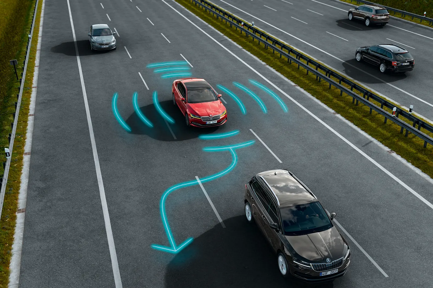
Drivers are taught to assess surrounding traffic before changing lanes by checking their rearview and side mirrors and looking over each shoulder. However, even for those who follow this sequence of checks, the vehicle's blind spot – the area alongside and just behind the vehicle – is a constant source of danger and often the cause of serious accidents. Even vehicles approaching quickly from behind can pose a risk. To make changing lanes safer, this feature has been developed.
4.Basic Working Principle:-
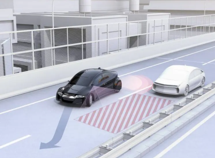
Highway Assistant is a partially automated driving function for a speed range of up to 180 km/h (112 mph) on highways. It combines the radar-based longitudinal guidance of Adaptive Cruise Control (ACC) with the video-based lateral guidance of lane-keeping support in one system. Highway Assistant can be supplemented by an automatic lane change initiated and monitored by the driver in a speed range of 60 – 130 km/h (35 – 80 mph).The Lane Change Assistant works by using two mid-range radar sensors that are concealed in the rear bumper – one on the left, one on the right. These two sensors monitor the area alongside and behind the car. Powerful control software collates the sensor information to create a complete picture of all traffic in the area behind the vehicle. Whenever another vehicle approaches at speed from behind or is already present in the blind spot, a signal such as a warning light in the side mirror alerts the driver to the hazard. Should the driver still activate the turn signal with the intention of changing lanes, the system issues an additional acoustic and/or haptic warning.
5.Calibration and Signal Data List:-
Input Signals:-
|
Name of the Signal |
Data Type |
Range |
|
Highway_Input_Signal |
uint8 |
0 - 255 |
|
Enable_Display |
uint8 |
0 – 255 |
|
Input_Switch |
uint8 |
0 – 255 |
|
Lane_Input_Signal |
uint8 |
0 - 255 |
Local Signals:-
|
Name of the Signal |
Data Type |
Range |
|
Highway_Display_Mode_1 |
uint8 |
0 - 255 |
|
Highway_Display_Mode_2 |
uint8 |
0 – 255 |
|
Highway_Display_Mode_3 |
uint8 |
0 – 255 |
|
Highway_Display_Mode_4 |
uint8 |
0 – 255 |
|
Lane_Display_Mode_1 |
uint8 |
0 – 255 |
|
Lane_Display_Mode_2 |
uint8 |
0 – 255 |
|
Lane_Display_Mode_3 |
uint8 |
0 – 255 |
|
Lane_Display_Mode_4 |
uint8 |
0 – 255 |
Output Signals:-
|
Name of the Signal |
Data Type |
Range |
|
Display_Mode_1 |
uint8 |
0 - 255 |
|
Display_Mode_2 |
uint8 |
0 – 255 |
|
Display_Mode_3 |
uint8 |
0 – 255 |
|
Display_Mode_4 |
uint8 |
0 - 255 |
6.Requirements:-
Requirement No 1 [Highway_DisplayUnit]:-
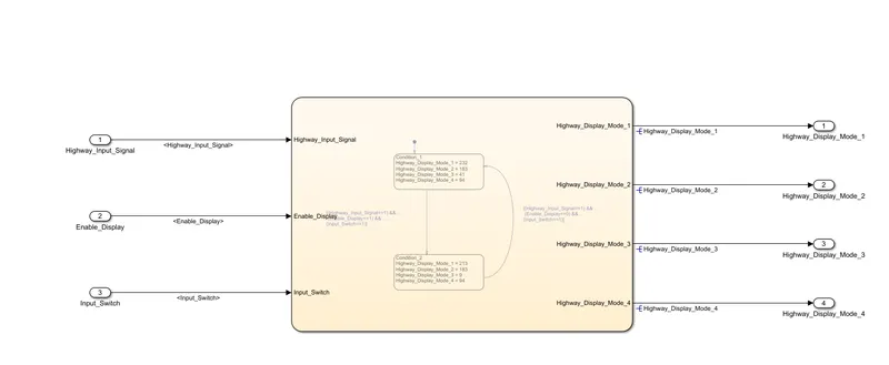
Inputs to this particular subsystem are “Highway_Input_Signal”, “Enable_Display”, “Input_Switch”. These three input signals, when assigned to a particular value will give output signals of specific value. The output signals are “Highway_Display_Mode_1”, “Highway_Display_Mode_2”, “Highway_Display_Mode_3”, “Highway_Display_Mode_4”. The requirement must be implemented in the form of a Stateflow logic.
|
Condition |
Action |
|
Highway_Input_Signal = 1 Enable_Display = off Input_Switch = on |
Highway_Display_Mode_1 = 232 Highway_Display_Mode_2 = 183 Highway_Display_Mode_3 = 41 Highway_Display_Mode_4 = 94 |
|
Highway_Input_Signal = 1 Enable_Display = on Input_Switch = on |
Highway_Display_Mode_1 = 213 Highway_Display_Mode_2 = 183 Highway_Display_Mode_3 = 9 Highway_Display_Mode_4 = 94 |
Requirement No 2 [Lane_DisplayUnit]:-
Inputs to this particular subsystem are “Enable_Display”, “Input_Switch”, “Lane_Input_Signal”. These three input signals, when assigned to a particular value will give output signals of specific value. The output signals are “Lane_Display_Mode_1”, “Lane_Display_Mode_2”, “Lane_Display_Mode_3”, “Lane_Display_Mode_4”. The requirement must be implemented in the form of Stateflow logic.
|
Condition |
Action |
|
Lane_Input_Signal= 6 Enable_Display = off Input_Switch = on |
Lane_Display_Mode_1 = 132 Lane_Display_Mode_2 = 185 Lane_Display_Mode_3 = 54 Lane_Display_Mode_4 = 67 |
|
Lane_Input_Signal= 6 Enable_Display = on Input_Switch = on |
Lane_Display_Mode_1 = 127 Lane_Display_Mode_2 = 248 Lane_Display_Mode_3 = 186 Lane_Display_Mode_4 = 84 |
Requirement No 3:-
Signals coming from both subsystems “Highway_Display_Mode_1” & “Lane_Display_Mode_1” are given as inputs to a switch block which will have input signal “Highway_Input_Signal” given as 2nd input to the switch block. Corresponding output from this particular switch block is output signal “Display_Mode_1”.
Signals coming from both subsystems “Highway_Display_Mode_2” & “Lane_Display_Mode_2” are given as inputs to a switch block which will have input signal “Highway_Input_Signal” given as 2nd input to the switch block. Corresponding output from this particular switch block is output signal “Display_Mode_2”.
Signals coming from both subsystems “Highway_Display_Mode_3” & “Lane_Display_Mode_3” are given as inputs to a switch block which will have input signal “Highway_Input_Signal” given as 2nd input to the switch block. Corresponding output from this particular switch block is output signal “Display_Mode_3”.
Signals coming from both subsystems “Highway_Display_Mode_4” & “Lane_Display_Mode_4” are given as inputs to a switch block which will have input signal “Highway_Input_Signal” given as 2nd input to the switch block. Corresponding output from this particular switch block is output signal “Display_Mode_4”.
7.Procedure:-
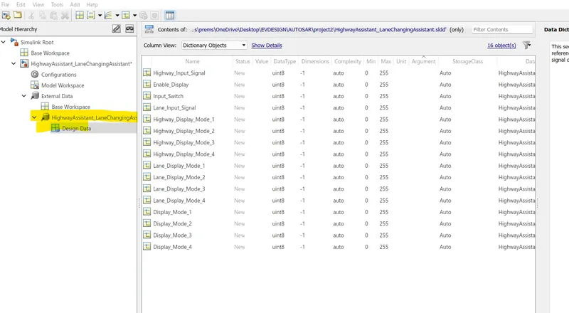
The first step is the creation of the Simulink Data Dictionary File from the given calibration and signal data list
Requirement No 1 [Highway_DisplayUnit]:-
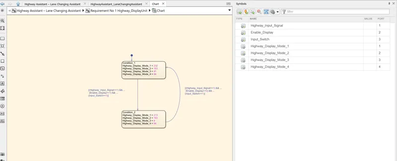
Inputs to this particular subsystem are “Highway_Input_Signal”, “Enable_Display”, “Input_Switch”. These three input signals, when assigned to a particular value will give output signals of specific value. The output signals are “Highway_Display_Mode_1”, “Highway_Display_Mode_2”, “Highway_Display_Mode_3”, “Highway_Display_Mode_4”. The requirement must be implemented in the form of a Stateflow logic.
|
Condition |
Action |
|
Highway_Input_Signal = 1 Enable_Display = off Input_Switch = on |
Highway_Display_Mode_1 = 232 Highway_Display_Mode_2 = 183 Highway_Display_Mode_3 = 41 Highway_Display_Mode_4 = 94 |
|
Highway_Input_Signal = 1 Enable_Display = on Input_Switch = on |
Highway_Display_Mode_1 = 213 Highway_Display_Mode_2 = 183 Highway_Display_Mode_3 = 9 Highway_Display_Mode_4 = 94 |
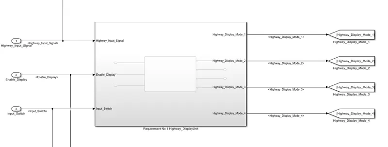
Inside of the requirement 1 sussystem,
Inside of the char show in below,
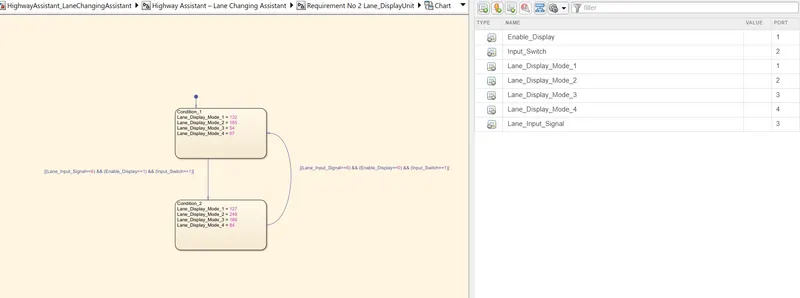
Requirement No 2 [Lane_DisplayUnit]:-
Inputs to this particular subsystem are “Enable_Display”, “Input_Switch”, “Lane_Input_Signal”. These three input signals, when assigned to a particular value will give output signals of specific value. The output signals are “Lane_Display_Mode_1”, “Lane_Display_Mode_2”, “Lane_Display_Mode_3”, “Lane_Display_Mode_4”. The requirement must be implemented in the form of Stateflow logic.
|
Condition |
Action |
|
Lane_Input_Signal= 6 Enable_Display = off Input_Switch = on |
Lane_Display_Mode_1 = 132 Lane_Display_Mode_2 = 185 Lane_Display_Mode_3 = 54 Lane_Display_Mode_4 = 67 |
|
Lane_Input_Signal= 6 Enable_Display = on Input_Switch = on |
Lane_Display_Mode_1 = 127 Lane_Display_Mode_2 = 248 Lane_Display_Mode_3 = 186 Lane_Display_Mode_4 = 84 |
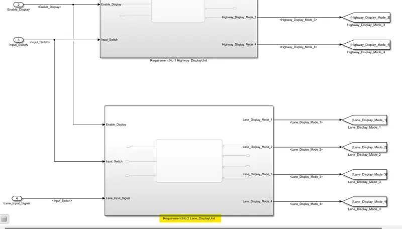
Inside of the requirement 2 subsystem,
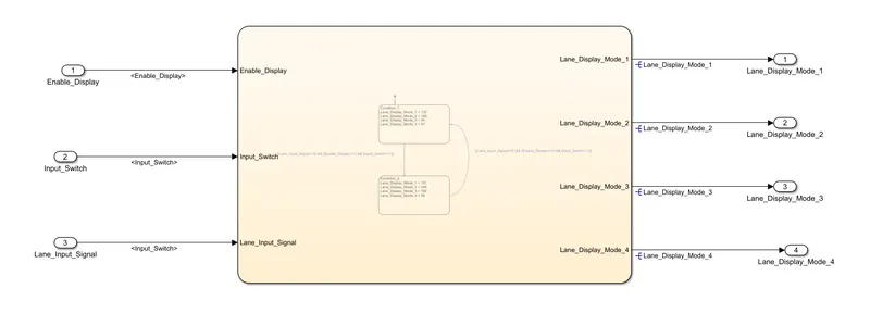
Inside of the char show in below,
Requirement No 3:-
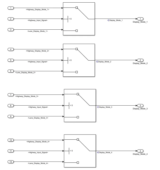
Signals coming from both subsystems “Highway_Display_Mode_1” & “Lane_Display_Mode_1” are given as inputs to a switch block which will have input signal “Highway_Input_Signal” given as 2nd input to the switch block. Corresponding output from this particular switch block is output signal “Display_Mode_1”.
Signals coming from both subsystems “Highway_Display_Mode_2” & “Lane_Display_Mode_2” are given as inputs to a switch block which will have input signal “Highway_Input_Signal” given as 2nd input to the switch block. Corresponding output from this particular switch block is output signal “Display_Mode_2”.
Signals coming from both subsystems “Highway_Display_Mode_3” & “Lane_Display_Mode_3” are given as inputs to a switch block which will have input signal “Highway_Input_Signal” given as 2nd input to the switch block. Corresponding output from this particular switch block is output signal “Display_Mode_3”.
Signals coming from both subsystems “Highway_Display_Mode_4” & “Lane_Display_Mode_4” are given as inputs to a switch block which will have input signal “Highway_Input_Signal” given as 2nd input to the switch block. Corresponding output from this particular switch block is output signal “Display_Mode_4”.
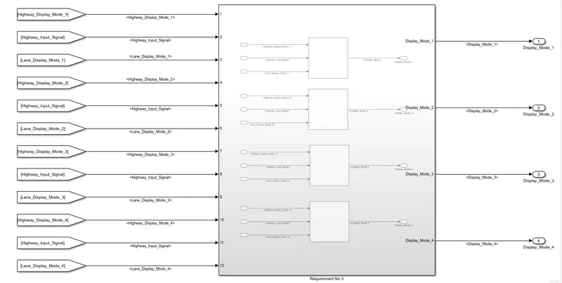
Inside of the requirement 3 subsystem,
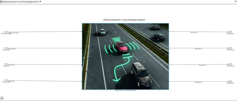
8. Highway Assistant – Lane Changing Assistant
main model for Highway Assistant – Lane Changing Assistant
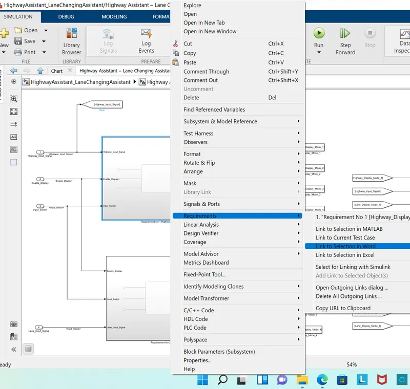
9.Requirement No 1 [Highway_DisplayUnit] Tagging of subsystem:-
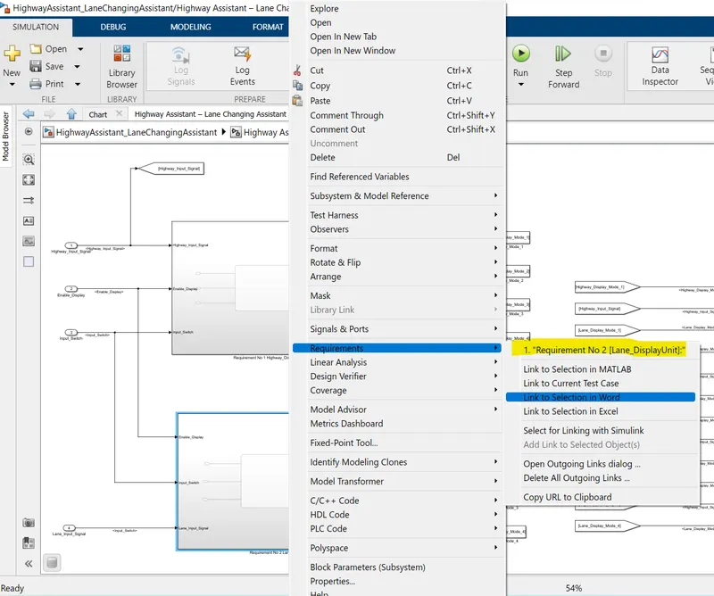
Requirement No 2 [Lane_DisplayUnit] Tagging of subsystem:-
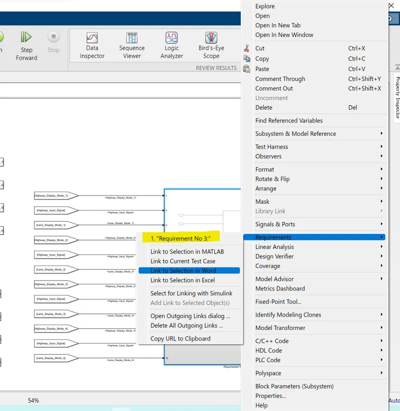
Requirement No 3 Tagging of subsystem:-
10.Model configuration parameters Updated:-
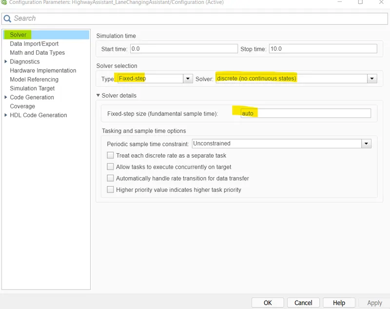
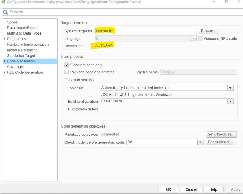
system target file was selected as autosar.tlc
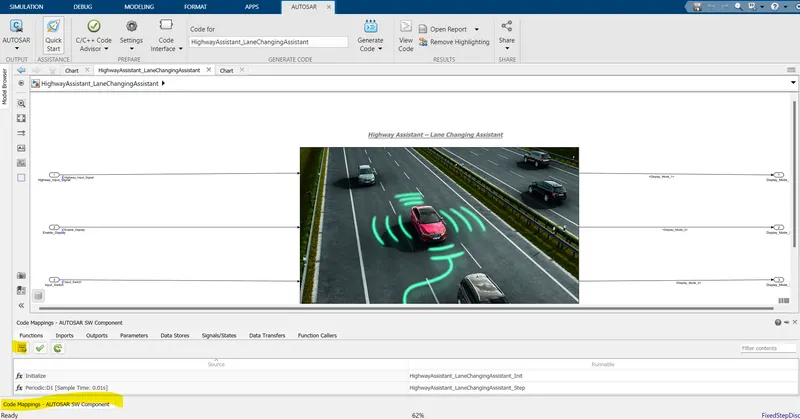
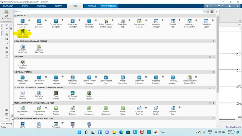
Now open the APPS and then open Autosar Dictionary
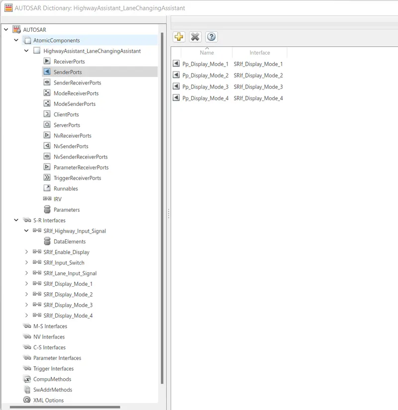
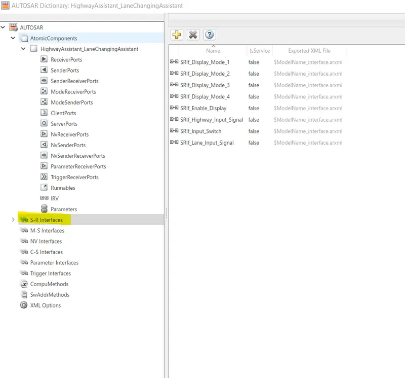
Then Autosa dictionary has to be created in which Sender, Receiver and S-R Interface has to be defined.
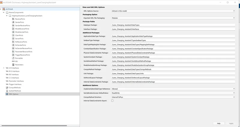
All the receriver ports (inputs) start with a prefix Rp
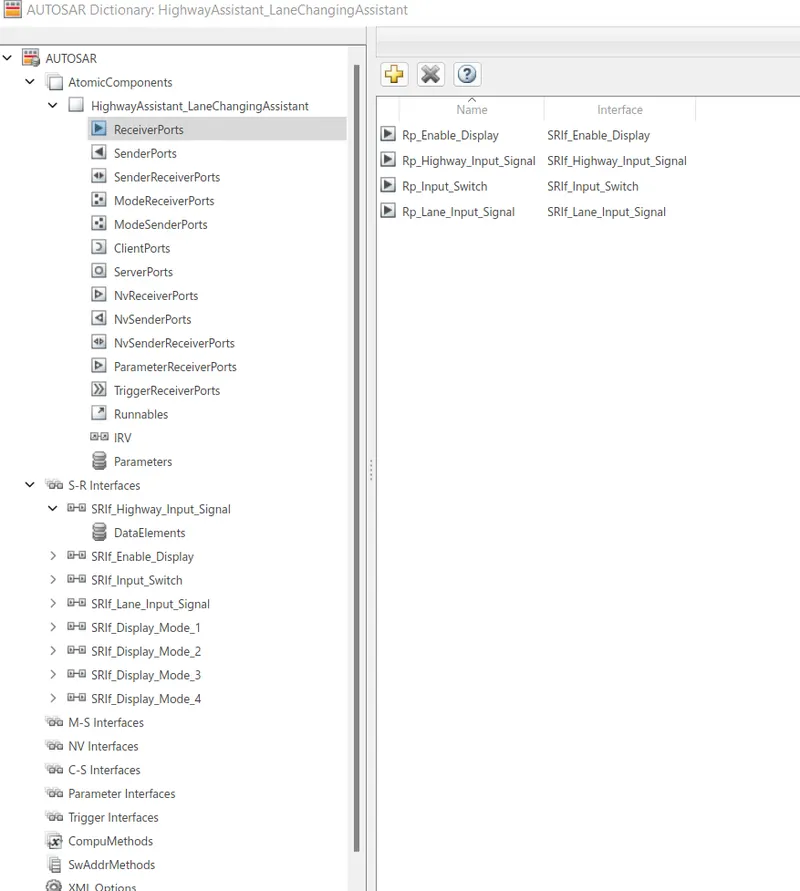
All the sender ports (outputs) start with a prefix Pp
All the S-R interfaces start with a prefix SRIF
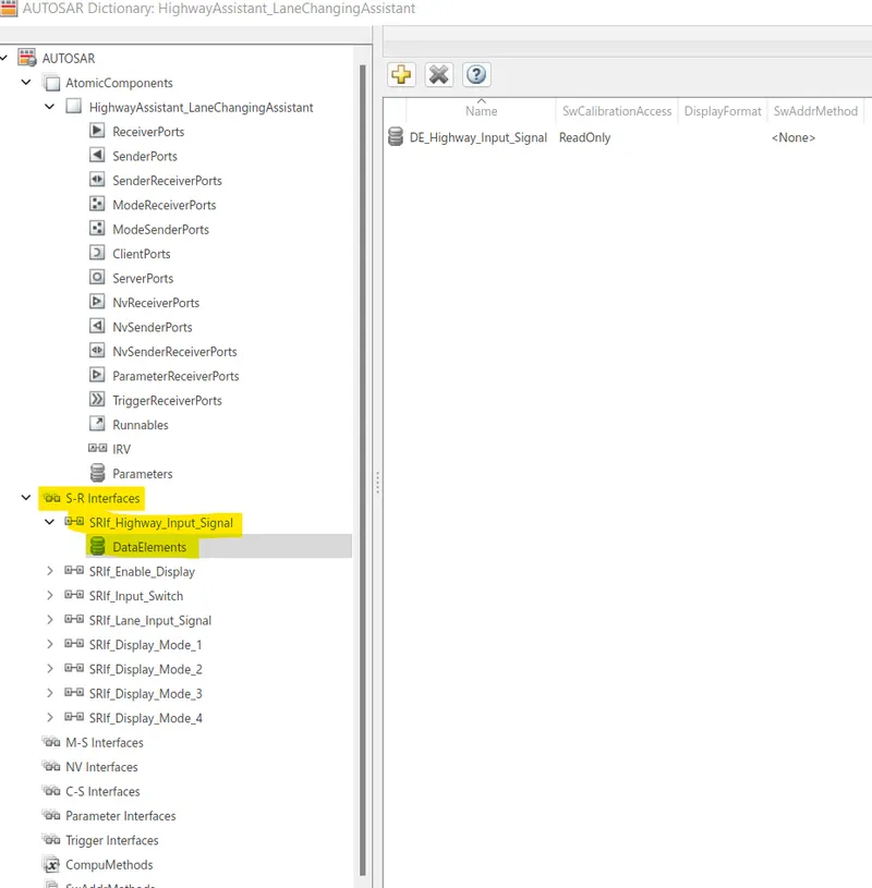
Now Changing SRIF_Highway_Input_Signal to DE_Highway_Input_Signal
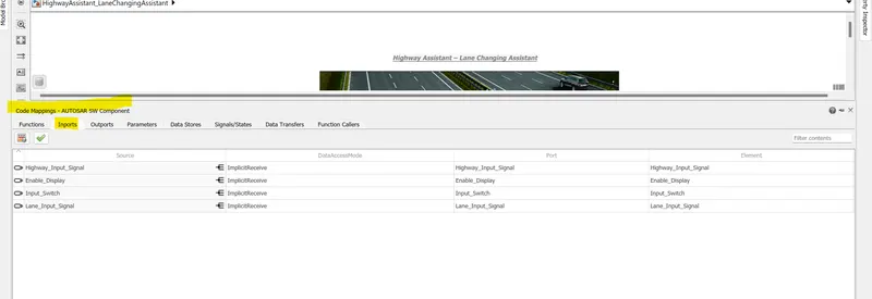
Afer that Inports and outports mapping has to be done.

After Changing the Autosar Components we can see the Validation Succeeded
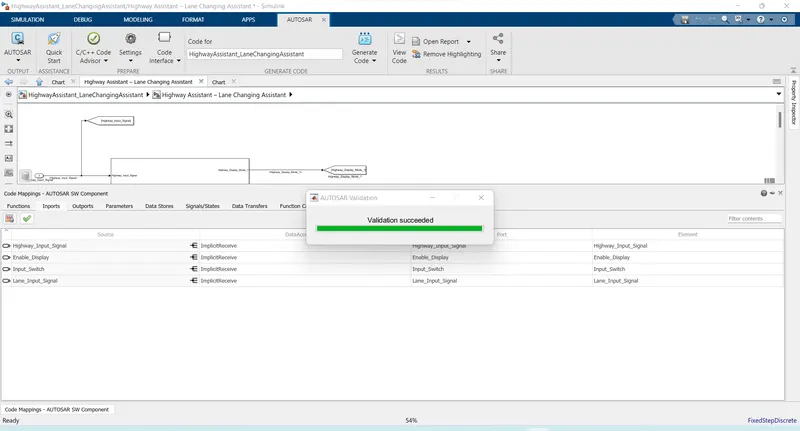
Once the ports mapping is done then the final task is to run the Model Advisor report and generate the code.
11.Signal Resolution for inputs and outputs:-
the inputs and output signals are resolved so the signals will take the values from sldd and pass them to the logical blocks. Otherwise, it may take some junkvalues if it is unresolved
12.Model Update:-
The model update is done by Ctrl-D. this is done to check for any static errors. If no errors are coming the model is working fine without any errors.
13.Simulation:-
The model is simulated too for checking for errors and warmings
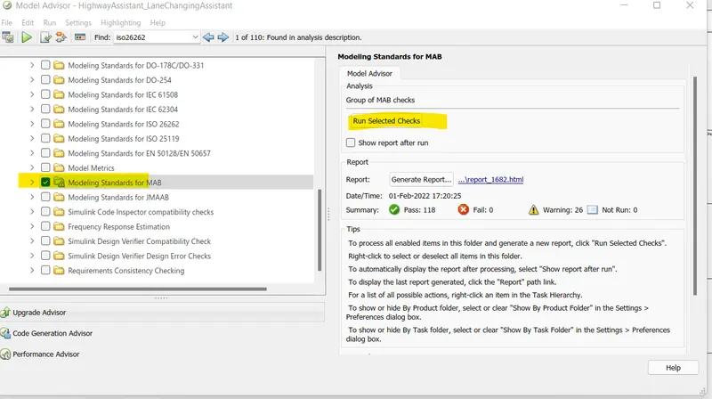
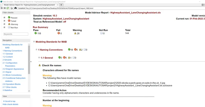
14.Model Advisory Report:-
By running the model advisor tool, we can see commonly made modeling errors.
15.Code generation:-
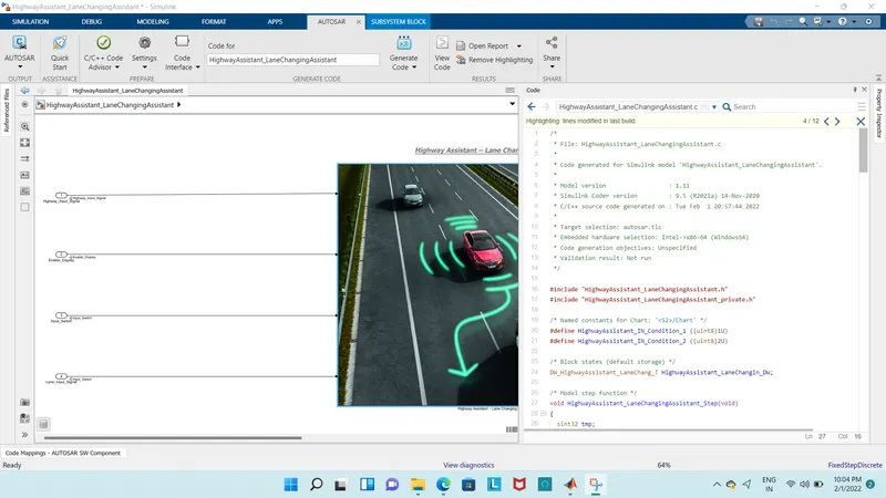
Build a model for generating code
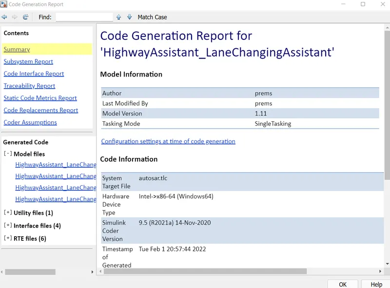
16.Generated Code :-
Developed a Model of a feature of Highway Assistant-Lane Changing Assistant as per MAAB guidelines, produced Model Advisor Report as well as generated Code using AUTOSAR Coder.