Week - 4
1(Q) ans:-
AIM:- Implement control logic of a “washing machine” using Stateflow as per given sequence:
- If the power supply is available, the system gets activated
- If the Water supply is not available, stop the process & indicate through LED
- Soaking time should be 200s followed by Washing time of 100s.
- Then rinsing happens for next 20s & dryer runs for 50s
After all the processes have completed turn on the finished LED..
REQUIRED BLOCK:- chart block ,constant,lamp slider switch,display
it is used to create a stateflow by6 using state.
description:-
washing machine:- they are two types of washingmachine 1.front load washing machine
2.top load washing machine
working of washing machine:-
the power supply and water is avilable and press the start button and fill the water it takes some time.than clothes and some saop oil soakig for some time.. then washing the clothes and rinsing after rinsing heater will be on then drying the water and finish the procees indiacte the led.
Blocks are used:-
chart block:-
a finite sate machine is a representational of an event -driven system.in an event model represent the trasition.
from one state to another state this transition is occured is the condition defining the change is true..
display:- the dispaly block is shows the value of the input data.
constant:- the block is used to give the some constat value the input.
lamp:- lamp is used to indicates color the value of the input signal.
slider switch:- it is used to on -off position indication the input is 0 the switch possion is off and iput is 1 possition of the switch is on state.. 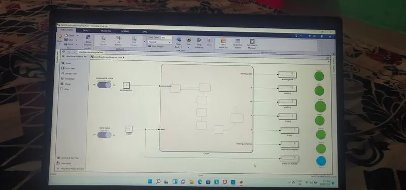
logic explanation:- a switch is from the dashboard library is used with coionstant supply the power and water. a lamp is used to indicate the power status and wter status.the power status is checked by the entry for every state the water status checked by the soaking and rinsing,washing prosses.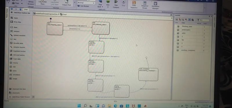
conditions:-
the above control logic first state is created with 2 conditions for power supply.
one is with power avialable (powerswitch==1)and second one is water supply avilable(water==1) if the power supply at entry is 1 water supply is on,the machine will get activated and prosses the next operations.
next 4 operations created state flows in order soaking,washing,rinsing,drying with time of operations as 200sec for soakink,and 100sec for washing,10sec for rinsing,50 sec for drying.is shown in above fig.entry and exit for condition are 1 is entry and 0 is exit conditiond.the operation is completed it is 1 for evry sates.
after all prosses done washing machine is off led indicated..and check the sequence of operation for 370sec..
green lamp is indicates the prosses done (soaking,was,dry,rin) other wise not done...
2(Q)ANS:-
Make a Simulink chart for the “Gear shift” logic as per below conditions:
Speed Range(kmph) Gear
0 to 15 1
16 to 25 2
26 to 40 3
41 to 60 4
Above 61 5
Give speed input while the simulation is running & display the gear number.
blocks ar use to build this model:-chart block,constant,slider,rockerswitch,display,lamp
chart block:- a finite sate machine is a representational of an event -driven system.in an event model represent the
trasition. from one state to another state this transition is occured is the condition defining the change is true..
display:- the dispaly block is shows the value of the input data.
constant:- the block is used to give the some constat value the input.
lamp:- lamp is used to indicates color the value of the input signal.
slider:- slider block is used to set values of connected block parameter.it is used to tune the values during simulation.
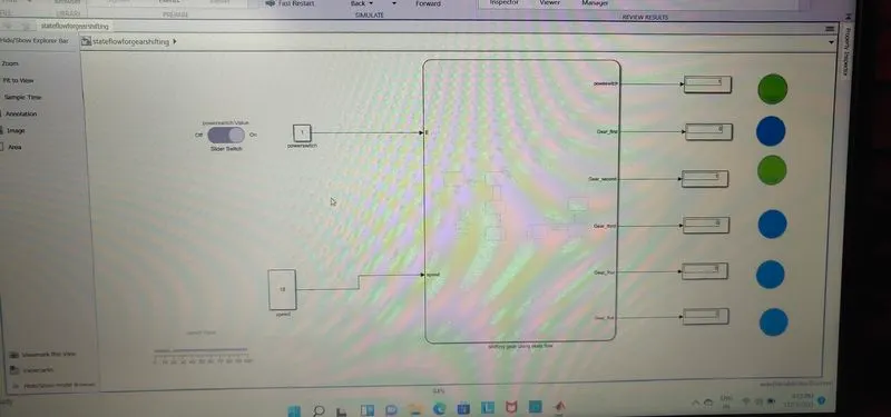
logiacl explanation:- switch is used to engine off and on state.slider is used to constant block,change the slider value during simulation. these are the inputs of the gearshifting stateflow.
- byusing state to create a condition of the two states
- lamp is used to indiacte the speed change by the gear .display is used to display the gear with respect to change the speed
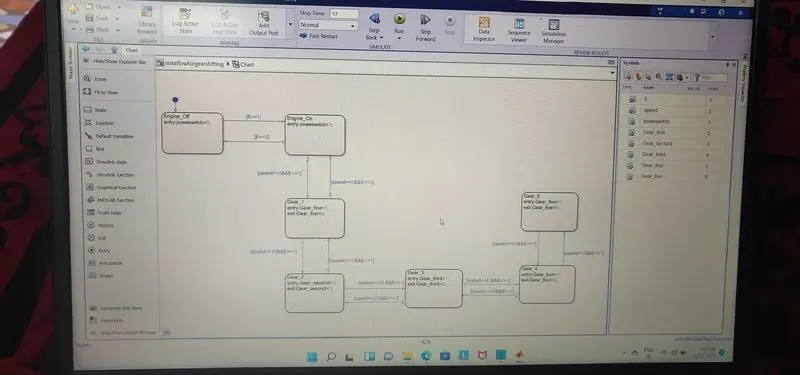
logical conditions:-
- here (E==1)and (E==0) are used to engine OFF/ON state by using these conditions
- (speed>=16&&E==1),(speed>=26&&E==1),(speed>=41)&&E==1(speed>=61&&E==1) these conditions are used to indiacte the gear positions like(1,2,3,4,5)..
the transition conditions for the gear shift is decided as
- speed>15shift to Gear=2
- speed>25shift to Gear=3
- speed>40shift Gear=4
speed>60shift Gear =5 increasing the speed is above 0-60kmph..
similarly in reverse direction speed will be dicreased.
- speed<60shift geaar =4
- speed<40shift gear=3
- speed<25shift gear=2
- speed<15shift gear =1
speed is dicreasing from 60-0kmph....