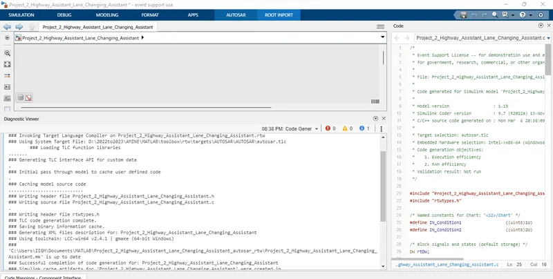
Project 2-Highway Assistant-Lane Changing Assistant
Problem Statement:
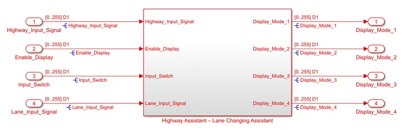
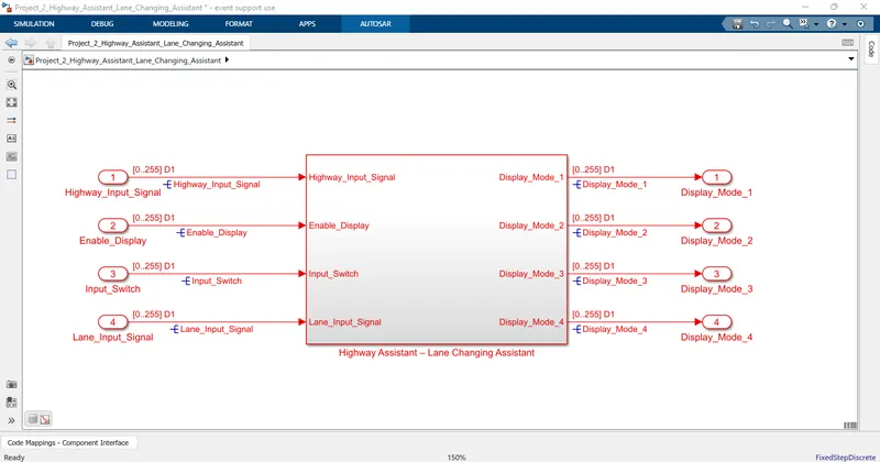
To develop one specific requirement of Highway Assistant – Lane Changing Assistant algorithm. Please note that the whole Highway Assistant – Lane Changing Assistant is a very huge algorithm & only one small part of the logic is implemented here. Idea is to familiarize with concepts of Autosar Software Component Development in MATLAB Environment by following the Model Based Development guidelines. The Project must be done keeping in mind the following processes & steps.
- This model must be developed in MATLAB Simulink per MBD guidelines.
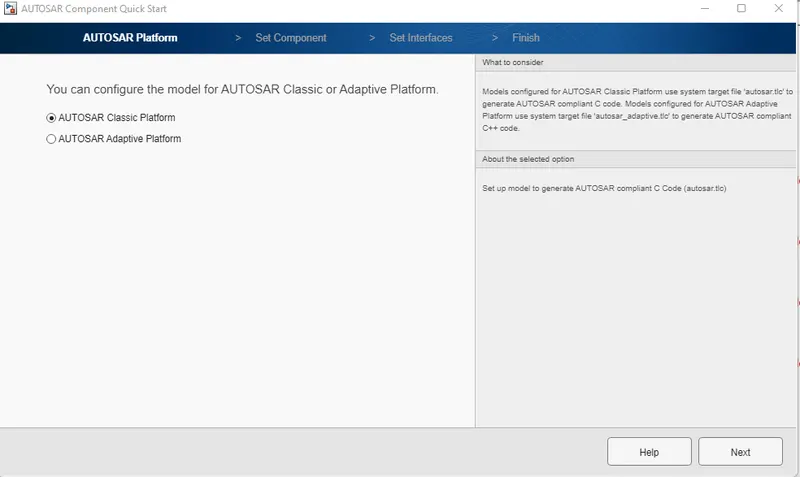
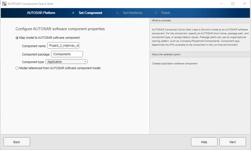
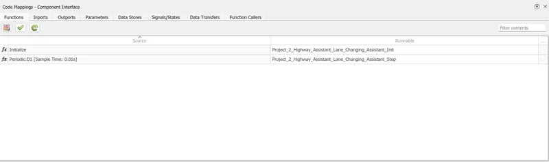
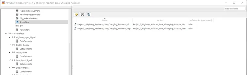
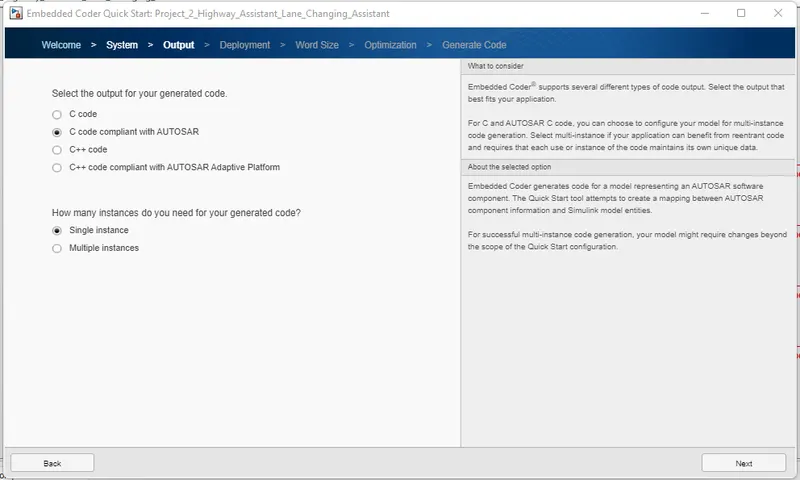
- Code Generation Profile must be Autosar Coder.
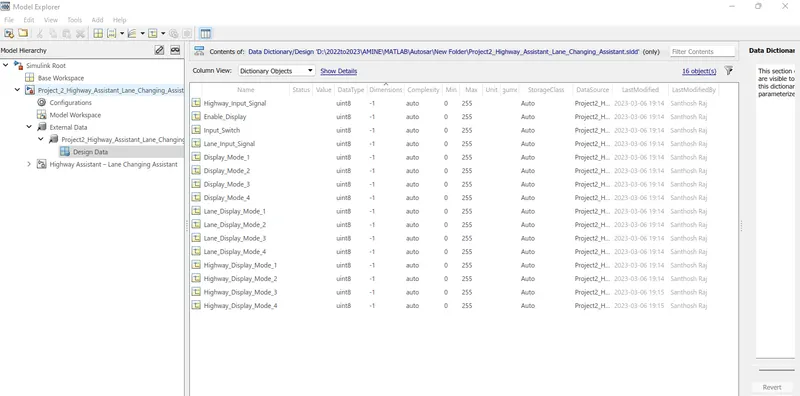
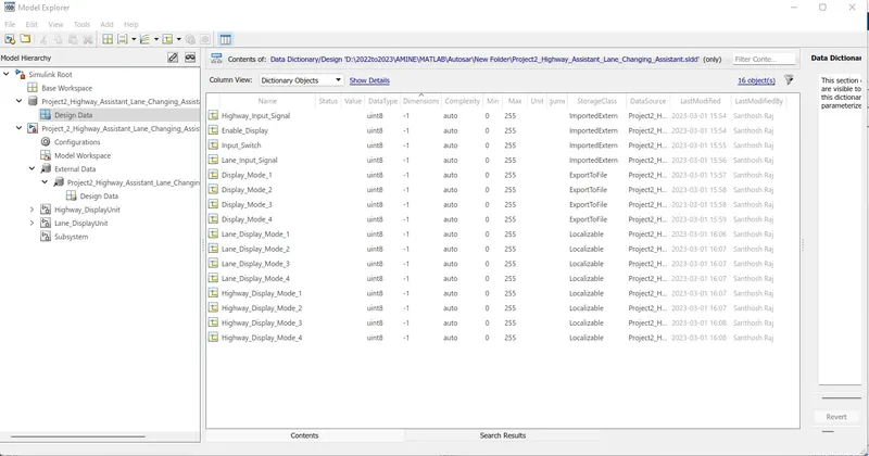
- Simulink Data Dictionary must be created for the model & must be linked to the model.
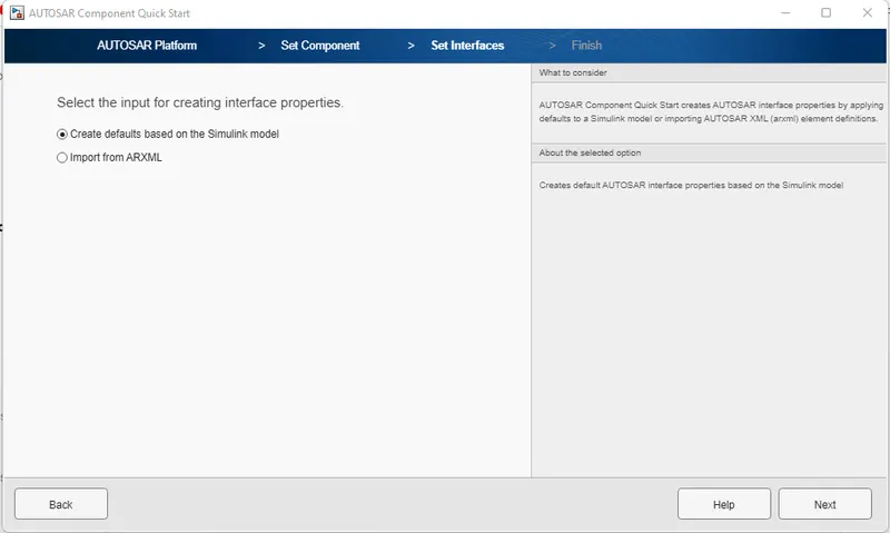
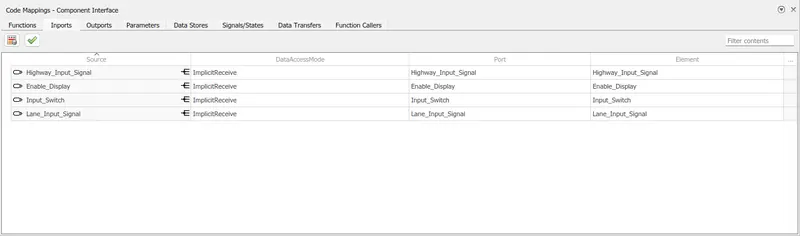
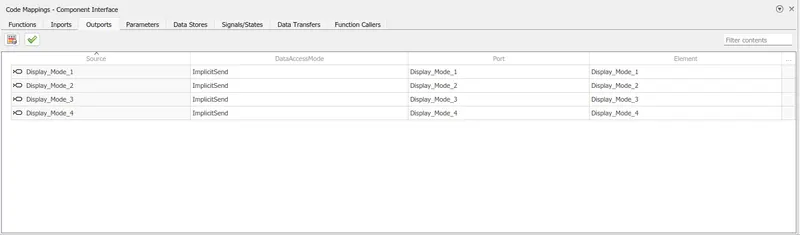
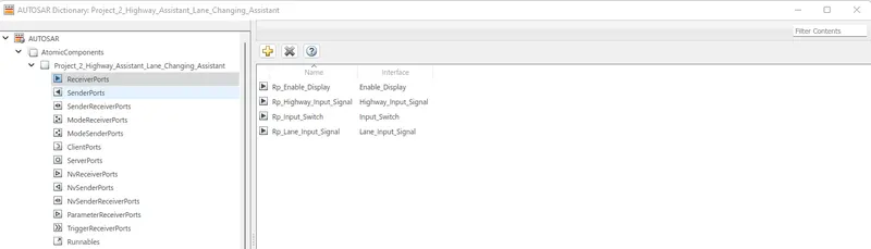
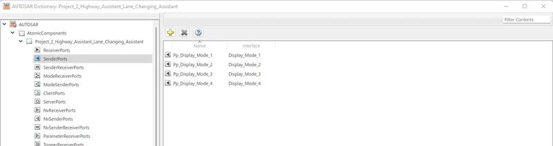
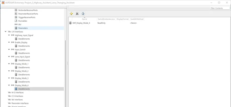
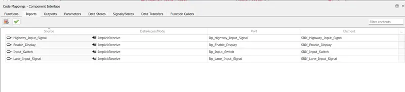
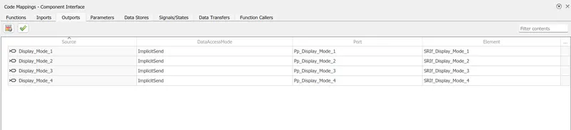
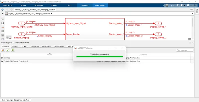
- All the input & output signals must be mapped into the Autosar Editor.
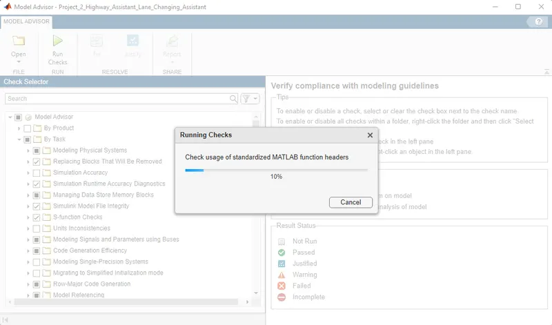
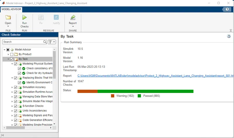
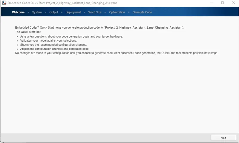
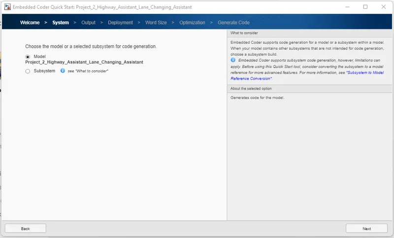
- Model Advisor Report is mandatory & this will be followed by Code Generation.
Creating SLDD File as per given signals
Input Signals:
|
Name of the Signal |
Data Type |
Range |
|
Highway_Input_Signal |
uint8 |
0 - 255 |
|
Enable_Display |
uint8 |
0 – 255 |
|
Input_Switch |
uint8 |
0 – 255 |
|
Lane_Input_Signal |
uint8 |
0 - 255 |
Local Signals:
|
Name of the Signal |
Data Type |
Range |
|
Highway_Display_Mode_1 |
uint8 |
0 - 255 |
|
Highway_Display_Mode_2 |
uint8 |
0 – 255 |
|
Highway_Display_Mode_3 |
uint8 |
0 – 255 |
|
Highway_Display_Mode_4 |
uint8 |
0 – 255 |
|
Lane_Display_Mode_1 |
uint8 |
0 – 255 |
|
Lane_Display_Mode_2 |
uint8 |
0 – 255 |
|
Lane_Display_Mode_3 |
uint8 |
0 – 255 |
|
Lane_Display_Mode_4 |
uint8 |
0 – 255 |
Output Signals:
|
Name of the Signal |
Data Type |
Range |
|
Display_Mode_1 |
uint8 |
0 - 255 |
|
Display_Mode_2 |
uint8 |
0 – 255 |
|
Display_Mode_3 |
uint8 |
0 – 255 |
|
Display_Mode_4 |
uint8 |
0 - 255 |
Requirement No 1 [Highway_DisplayUnit]:
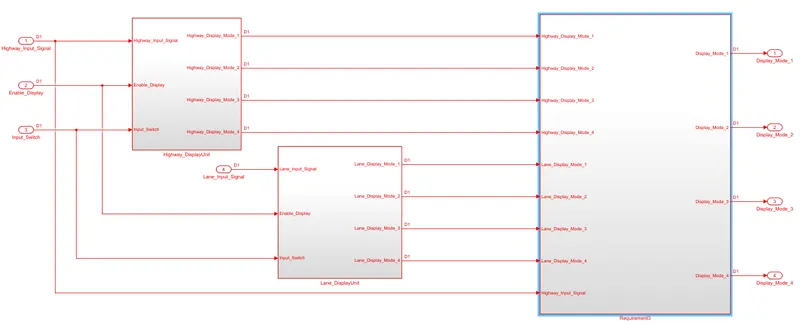
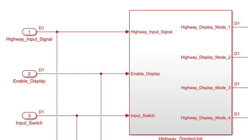
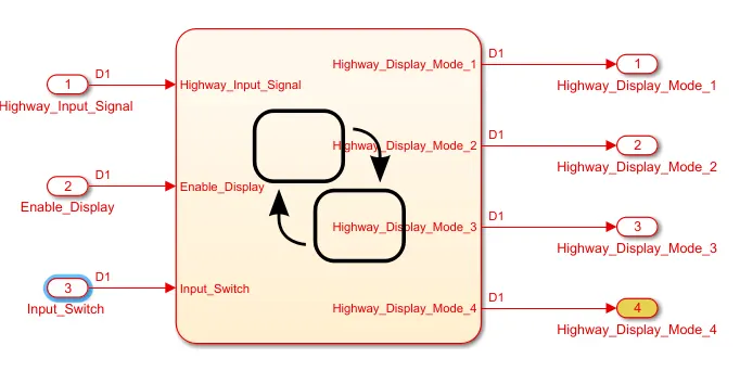
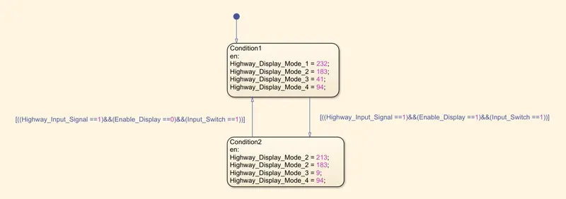
Inputs to this particular subsystem are “Highway_Input_Signal”, “Enable_Display”, “Input_Switch”. These three input signals, when assigned to a particular value will give output signals of specific value. The output signals are “Highway_Display_Mode_1”, “Highway_Display_Mode_2”, “Highway_Display_Mode_3”, “Highway_Display_Mode_4”. The requirement must be implemented in the form of a Stateflow logic.
|
Condition |
Action |
|
Highway_Input_Signal = 1 Enable_Display = off Input_Switch = on |
Highway_Display_Mode_1 = 232 Highway_Display_Mode_2 = 183 Highway_Display_Mode_3 = 41 Highway_Display_Mode_4 = 94 |
|
Highway_Input_Signal = 1 Enable_Display = on Input_Switch = on |
Highway_Display_Mode_1 = 213 Highway_Display_Mode_2 = 183 Highway_Display_Mode_3 = 9 Highway_Display_Mode_4 = 94 |
Requirement No 2 [Lane_DisplayUnit]:
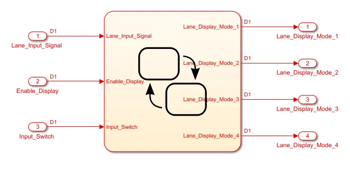
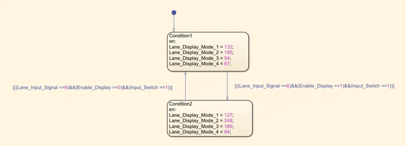
Inputs to this particular subsystem are “Enable_Display”, “Input_Switch”, “Lane_Input_Signal”. These three input signals, when assigned to a particular value will give output signals of specific value. The output signals are “Lane_Display_Mode_1”, “Lane_Display_Mode_2”, “Lane_Display_Mode_3”, “Lane_Display_Mode_4”. The requirement must be implemented in the form of Stateflow logic.
|
Condition |
Action |
|
Lane_Input_Signal= 6 Enable_Display = off Input_Switch = on |
Lane_Display_Mode_1 = 132 Lane_Display_Mode_2 = 185 Lane_Display_Mode_3 = 54 Lane_Display_Mode_4 = 67 |
|
Lane_Input_Signal= 6 Enable_Display = on Input_Switch = on |
Lane_Display_Mode_1 = 127 Lane_Display_Mode_2 = 248 Lane_Display_Mode_3 = 186 Lane_Display_Mode_4 = 84 |
Requirement No 3:
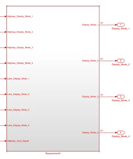
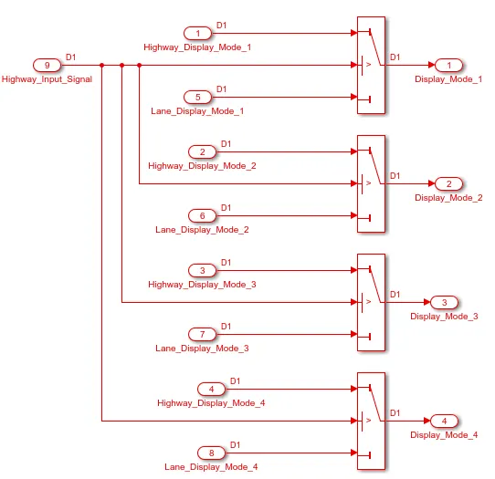
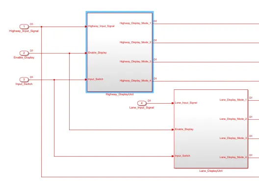
Signals coming from both subsystems “Highway_Display_Mode_1” & “Lane_Display_Mode_1” are given as inputs to a switch block which will have input signal “Highway_Input_Signal” given as 2nd input to the switch block. Corresponding output from this particular switch block is output signal “Display_Mode_1”.
Signals coming from both subsystems “Highway_Display_Mode_2” & “Lane_Display_Mode_2” are given as inputs to a switch block which will have input signal “Highway_Input_Signal” given as 2nd input to the switch block. Corresponding output from this particular switch block is output signal “Display_Mode_2”.
Signals coming from both subsystems “Highway_Display_Mode_3” & “Lane_Display_Mode_3” are given as inputs to a switch block which will have input signal “Highway_Input_Signal” given as 2nd input to the switch block. Corresponding output from this particular switch block is output signal “Display_Mode_3”.
Signals coming from both subsystems “Highway_Display_Mode_4” & “Lane_Display_Mode_4” are given as inputs to a switch block which will have input signal “Highway_Input_Signal” given as 2nd input to the switch block. Corresponding output from this particular switch block is output signal “Display_Mode_4”.