AIM: To develop a Highway Assistant – Lane Changing Assistant model in Matlab Simulink as per MBD guidelines and producing model advisory report followed by code generation using Autosar coder
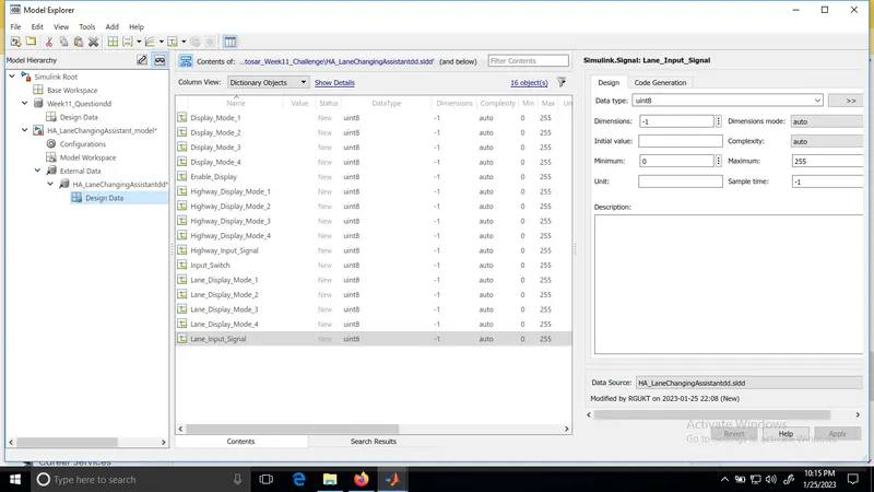
Step1: Creating Simulink data dictionary for the given signals list
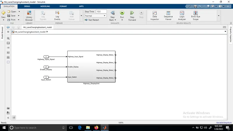
Step2: Implementation of Requirement No 1 [Highway_DisplayUnit]
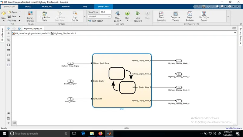
Created a subsystem with three inputs namely 'Highway_Input_Signal', 'Enable_Display' and 'Input_Switch'.
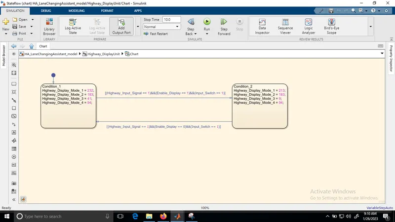
As per the requirement1, the logic is implemented in the chart block inside the sub sysytem with four outputs 'Highway_Display_Mode_1', 'Highway_Display_Mode_2', 'Highway_Display_Mode_3 and 'Highway_Display_Mode_4'.
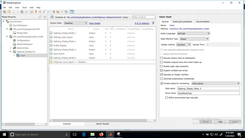
After writing the logic in the chart block, signals used in it must be mapped to input and outports ports in the model explorer
Step3: Implementation of Requirement No 2 [Lane_DisplayUnit]
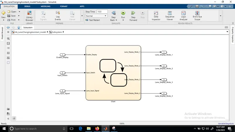
Created a subsystem with three inputs: 'Enable_Display', 'Input_Switch', 'Lane_Input_Signal'.
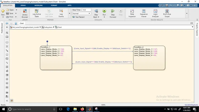
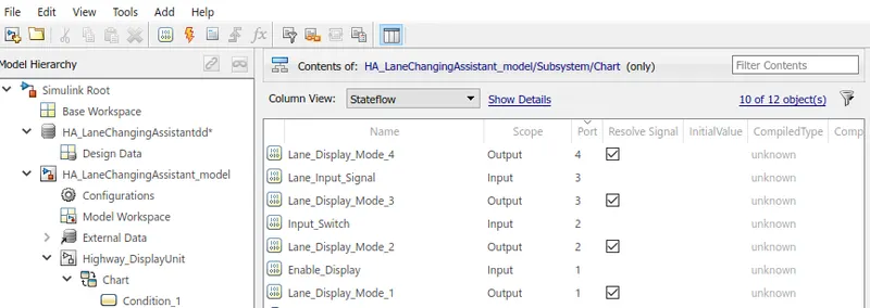
As per the requirement2, the logic is implemented in the chart block inside the sub sysytem with four outputs: 'Lane_Display_Mode_1', 'Lane_Display_Mode_2', 'Lane_Display_Mode_3', 'Lane_Display_Mode_4.
Inside the chart, the logic is written
The input and output signals are then resolved
Step 4: Implementation of Requirement 3:
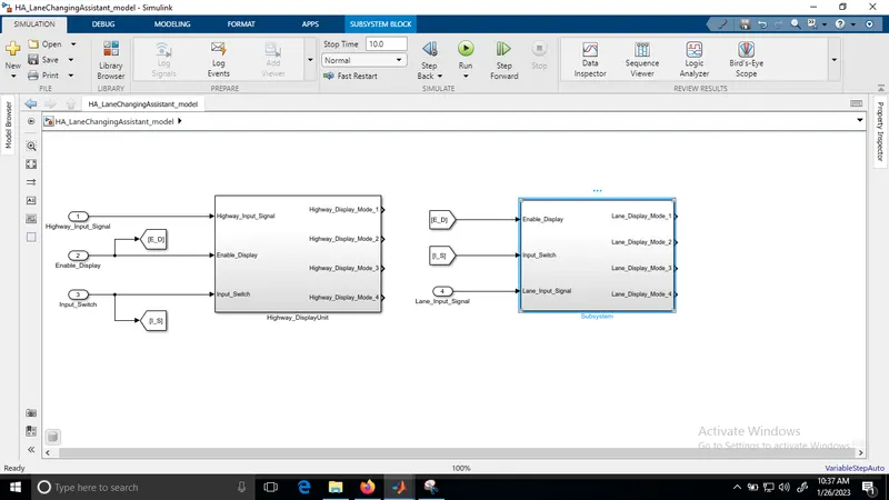
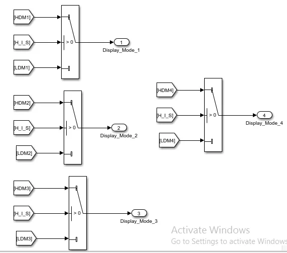
The output of the Highway_Display_Mode and Lane_Display_Mode are provided to the Switch block. That is in total 4 switch blocks are used. The conditional input signal is taken as Highway_Input_Signal for all the blocks.
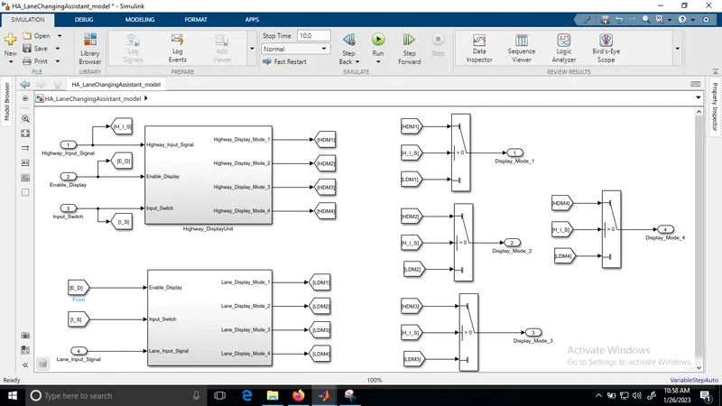
The final model is shown below
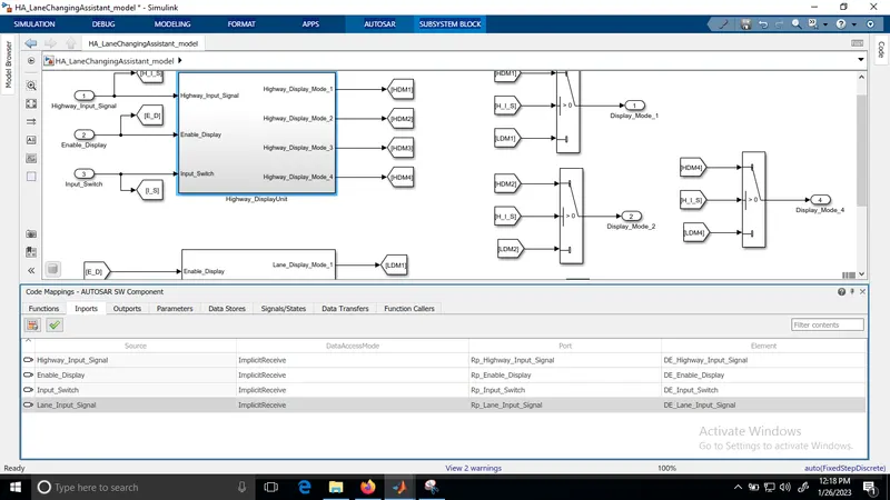
Step 5: Mapping of input and output signals into the Autosar Editor to make the model in compliance with the AUTOSAR
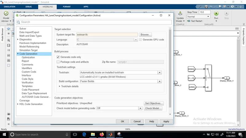
i)Code Generation settings: System target file to autosar.tlc
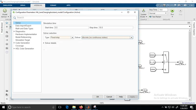
ii) Solver settings: Type to fixed step and Solver to discrete
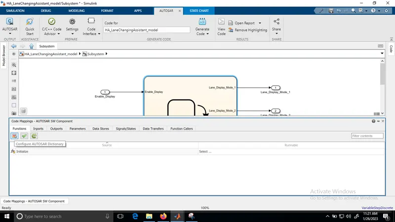
iii) Goto APPS-->Autosar Component
Open the Code Mapping- Auosar Software Component
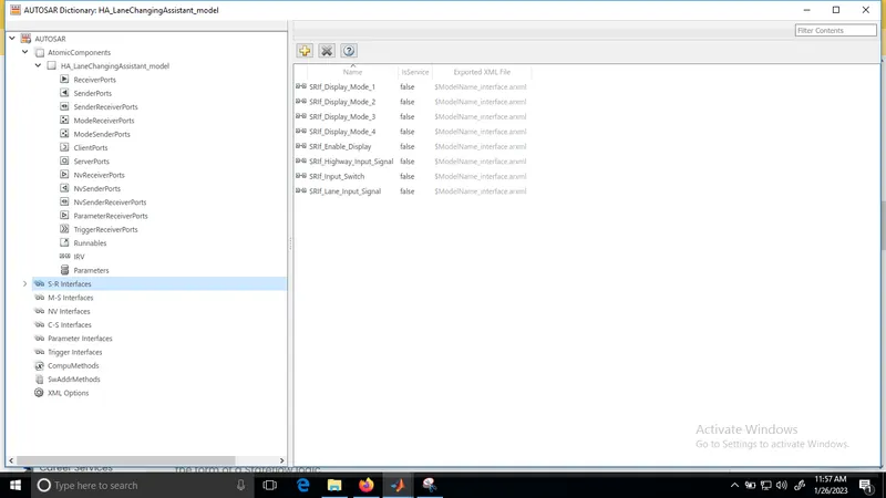
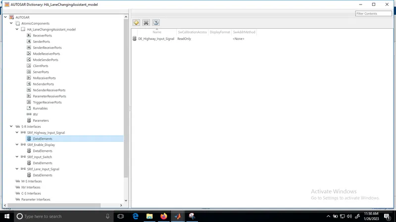
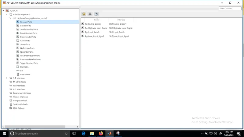
iv) Interfaces for the 4 input ports & their corresponding Data elements are created
For the S-R Interfaces of the model, we will rename the port with the prefix SRIf_.
For the Data Elements of the model, we will rename the port with the prefix DE_
v) Add inputs under receiver port section
For the Reciever port of the model, that is input, we will rename the port with the prefix Rp_
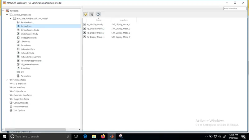
vi) Add oututs under sender port section
For the Sender port of the model, that is output, we will rename the port with the prefix Pp_.
Autosar dictionary is configured
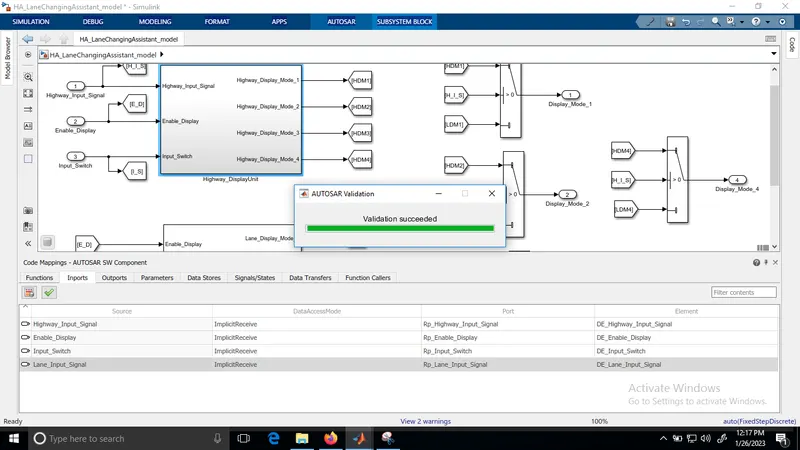
Step 6: Model validation with AUTOSAR Compliance
Click on the right mark for model validation
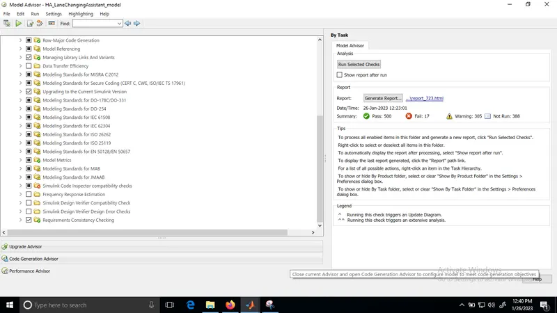
Step 7: Model Advisory Report
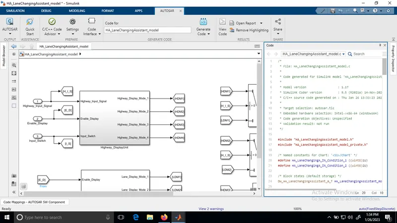
Step 8: Code Generation
/*
* File: HA_LaneChangingAssistant_model.c
*
* Code generated for Simulink model 'HA_LaneChangingAssistant_model'.
*
* Model version : 1.17
* Simulink Coder version : 9.5 (R2021a) 14-Nov-2020
* C/C++ source code generated on : Thu Jan 26 13:33:23 2023
Conclusion: Developed a Model of a feature of Highway Assistant-Lane Changing Assistant as per MAAB guidelines, produced Model Advisor Report as well as generated Code using AUTOSAR Coder