Project 1 (Mini Project on Vehicle Direction Detection
AIM: To develop a MATLAB Simulink model for determining the vehicle direction by taking two inputs SteeringWheel input and camera input.
Steps involved:
1. Take one subsystem with name 'Vehicle_Direction_Detection
2. Inputs to this system are steering wheel input as 'SteeringWheel_YawDegreeInput' in degress, camera input as 'CameraInput_RoadSign' and output is Vehicle_Direction_Indicator
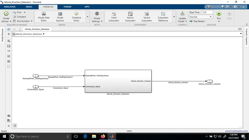
3. Requirement1 Implementation:
Take one sub system inside the 'Vehicle_Direction_Detection' and name it with 'Requirement1'.
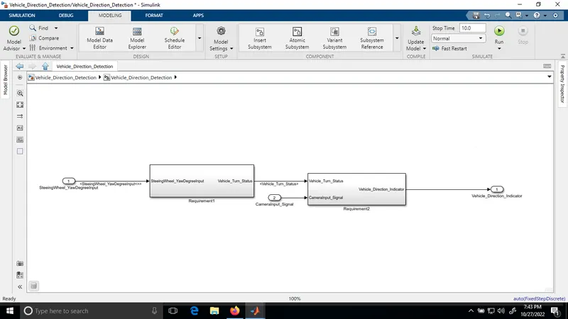
The following actions are implemented inside this subsystem
- Steering wheel input as yaw rate (Signal name: SteeringWheel_YawDegreeInput) is the input for this system.
- This is compared against 3 angular values, one each for left turn, right turn & straight drive (Calibration Values: Right_Turn_AngularLimit, Left_Turn_AngularLimit, Straight_Drive_Steering_Angle) to say which specific direction the steering wheel is turning towards.
- Use switch blocks to compare & develop this requirement. Keep this requirement in a subsystem & output of this requirement is a local signal (Signal Name: Vehicle_Turn_Status)
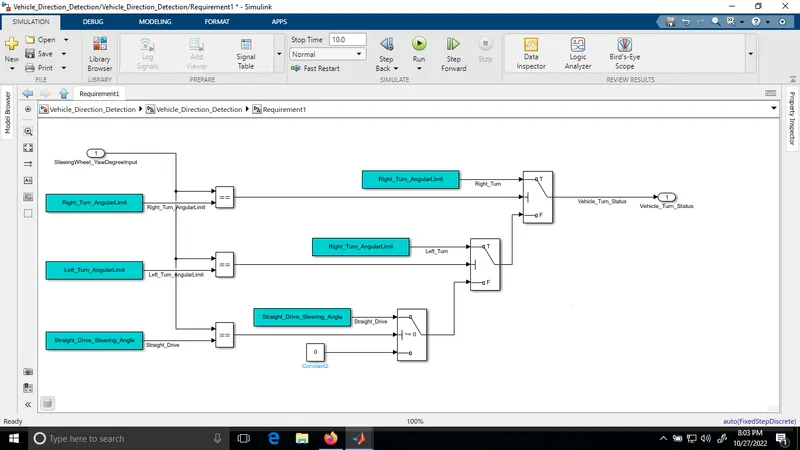
Here SteeringWheel_YawDegreeInput is compared against three calibrated constant values to decide the vehicle turn status to right, left or straigt with the help of relational operators and switch blocks
4. Requirement2 Implementation:
Take one more sub system inside the 'Vehicle_Direction_Detection' subsystem and name it with 'Requirement2'
The following actions are implemented inside this subsystem
- Inputs to this requirement are local signal from requirement 1 (Signal Name: Vehicle_Turn_Status) & an input signal from camera (Signal Name: CameraInput_RoadSign), which confirms the occurrence of a road sign.
- Signal Vehicle_Turn_Status is compared against calibration values (Calibration Values: RightTurn_RoadSign, LeftTurn_RoadSign, Straight_RoadSign), if each of them is found equal, then each of the three corresponding output is compared against the camera input signal,
- Using a logical operator block, only one among them is finally given as output signal (Signal Name: Vehicle_Direction_Indicator).
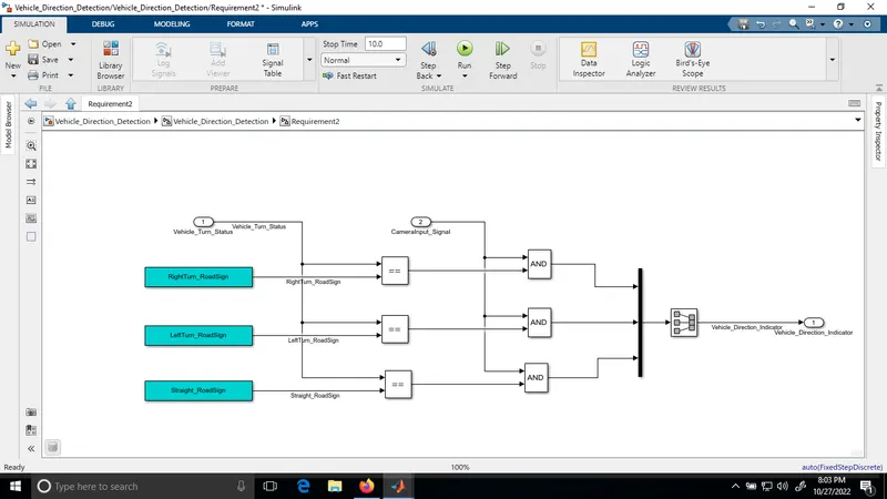
Here vehicle turn status is compared against three calibrated road sign constants and results were AND with camera input signal. The ouput of those AND gate are applied to the Mux and then through the signal conversion block the output of the subsystem is named as Vehicle_Direction_Indictaor.
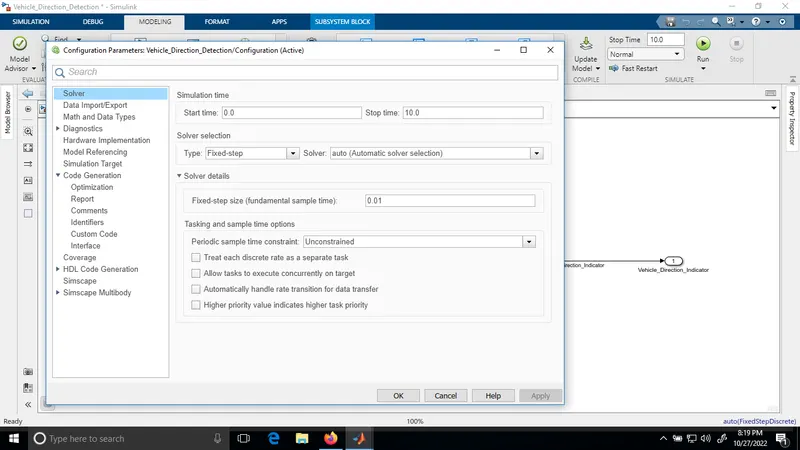
5. Configuration Parameter Settings:
do the solver settings as shown in the figure
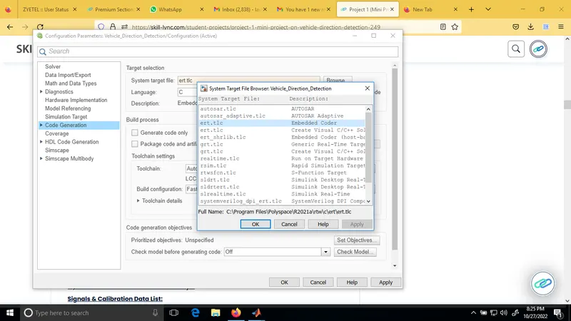
Under the Code generation option selecting embedded real time as system target file (ert.tlc) under target selection option.
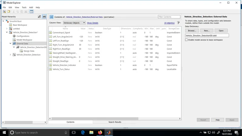
6. Create Simulink Data Dictionary for signals and calibrated constants
Simulink data dictionary is created with file name 'Vehicle_Direction_DetectionDD' and signals and constants are added as per the given specifications
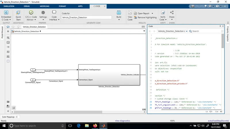
7. Code generation
Goto-->APPS-->Embedded Coder-->Press Build option
8. Requirement Taggings:
i) Copy the two requirements in the word file and saved it with name Project1.
ii) Select Requirement1 content in the word document
iii) Open the Simulink model, right click on Requirement do the following
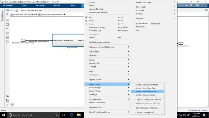
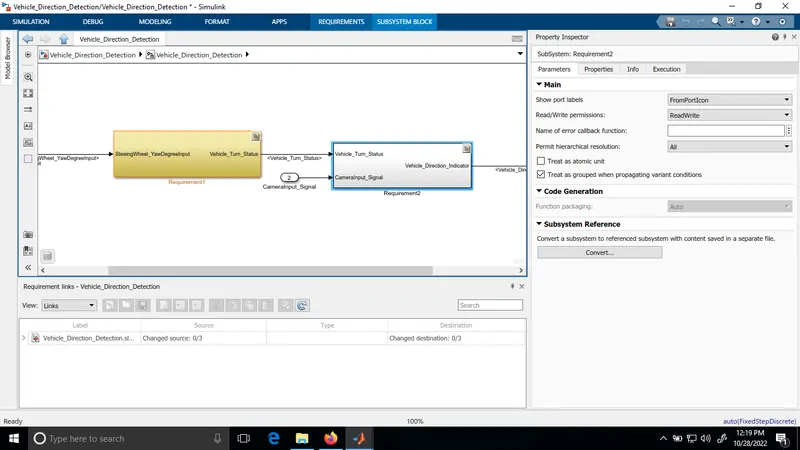
iv) Same procedure is extended for tagging Requirement2
v) Two requirements are tagged successfully
9. Model Advisor Report:
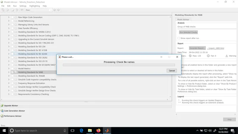
Modelling-->Model Advisor Report--->Select Model Standards for MAB--->Run selected checks
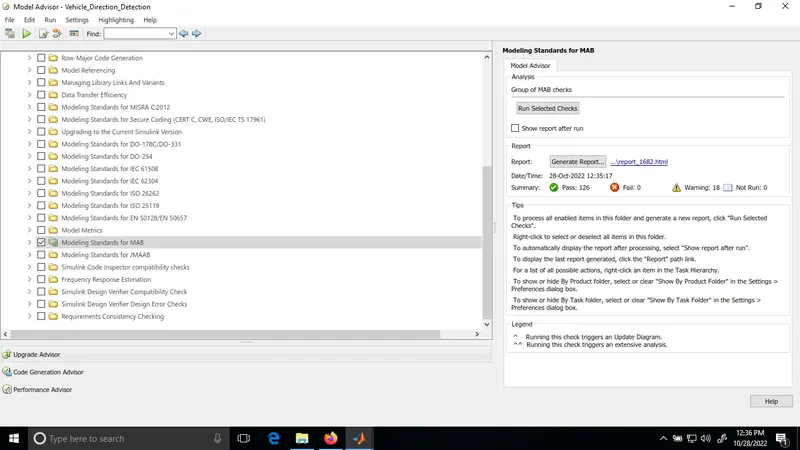
Result: Built the simulink model for Vehicle direction determination as per the given requirements