Project 2-Highway Assistant-Lane Changing Assistant
Aim:- Develop a model as per the given requirements and generate autosar software compile code.
OBJECTIVE:-
- This model must be developed in MATLAB Simulink per MBD guidelines.
- Code Generation Profile must be Autosar Coder.
- Simulink Data Dictionary must be created for the model & must be linked to the model.
- All the input & output signals must be mapped into the Autosar Editor.
- Model Advisor Report is mandatory & this will be followed by Code Generation.
Highway Assistant – Lane Changing Assistant
Introduction to the Feature:
The Highway Assistant supports the driver and takes over the longitudinal and lateral guidance of the vehicle in monotonous driving situations on highways. The partially automated function can automatically start, accelerate, brake as well as steer the vehicle to a certain extent. The driver has to permanently supervise the system and be ready to take over the complete control of the vehicle at any time.
Drivers are taught to assess surrounding traffic before changing lanes by checking their rearview and side mirrors and looking over each shoulder. However, even for those who follow this sequence of checks, the vehicle's blind spot – the area alongside and just behind the vehicle – is a constant source of danger and often the cause of serious accidents. Even vehicles approaching quickly from behind can pose a risk. To make changing lanes safer, this feature has been developed.
Basic Working Principle:
Highway Assistant is a partially automated driving function for a speed range of up to 180 km/h (112 mph) on highways. It combines the radar-based longitudinal guidance of Adaptive Cruise Control (ACC) with the video-based lateral guidance of lane keeping support in one system. Highway Assistant can be supplemented by an automatic lane change initiated and monitored by the driver in a speed range of 60 – 130 km/h (35 – 80 mph).
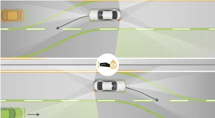
The lane Change Assistant works by using two mid-range radar sensors that are concealed in the rear bumper – one on the left, one on the right. These two sensors monitor the area alongside and behind the car. Powerful control software collates the sensor information to create a complete picture of all traffic in the area behind the vehicle.Whenever another vehicle approaches at speed from behind or is already present in the blind spot, a signal such as a warning light in the side mirror alerts the driver to the hazard. Should the driver still activate the turn signal with the intention of changing lanes, the system issues an additional acoustic and/or haptic warning.
Simulink Model Developement:
Step1: Requirement Analysis
Requirement No 1 [Highway_DisplayUnit]:
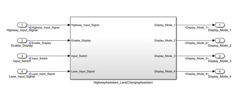
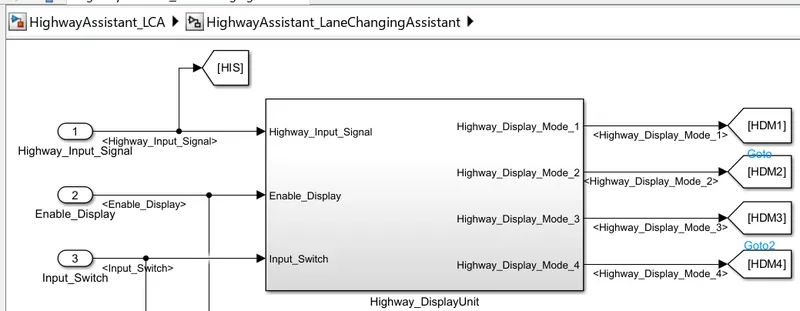
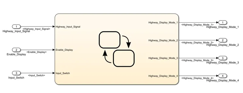
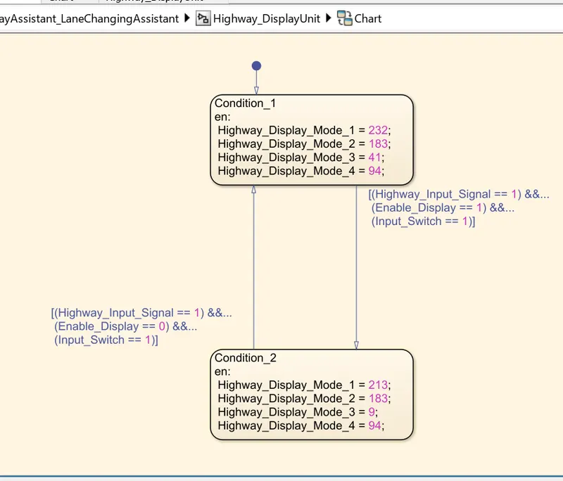
Inputs to this particular subsystem are “Highway_Input_Signal”, “Enable_Display”, “Input_Switch”. These three input signals, when assigned to a particular value will give output signals of specific value. The output signals are “Highway_Display_Mode_1”, “Highway_Display_Mode_2”, “Highway_Display_Mode_3”, “Highway_Display_Mode_4”. The requirement must be implemented in the form of a Stateflow logic.
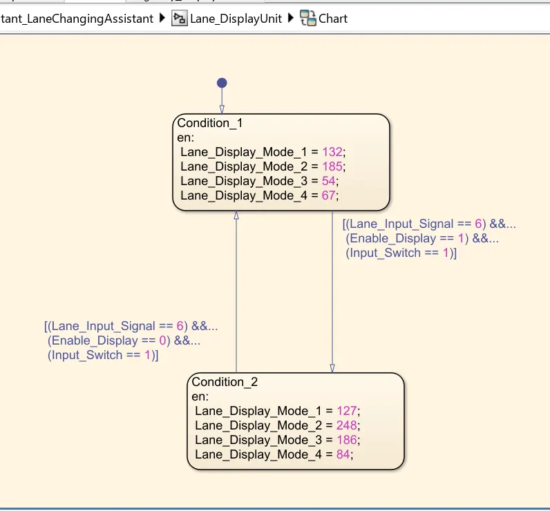
Requirement No 2 [Lane_DisplayUnit]:
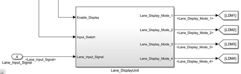
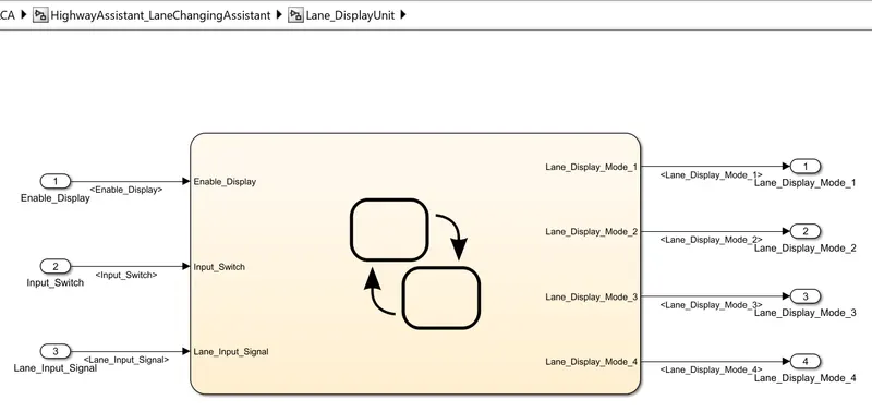
Inputs to this particular subsystem are “Enable_Display”, “Input_Switch”, “Lane_Input_Signal”. These three input signals, when assigned to a particular value will give output signals of specific value. The output signals are “Lane_Display_Mode_1”, “Lane_Display_Mode_2”, “Lane_Display_Mode_3”, “Lane_Display_Mode_4”. The requirement must be implemented in the form of Stateflow logic.
Requirement No 3:
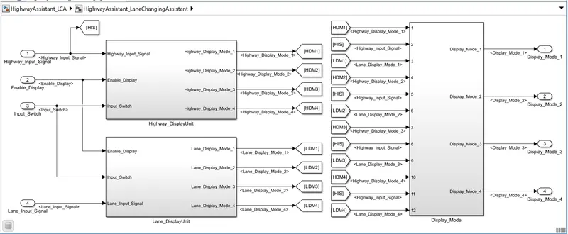
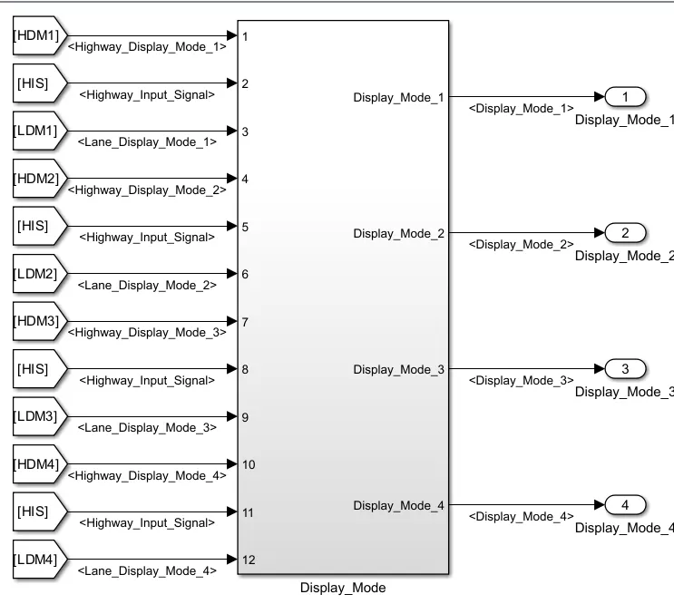
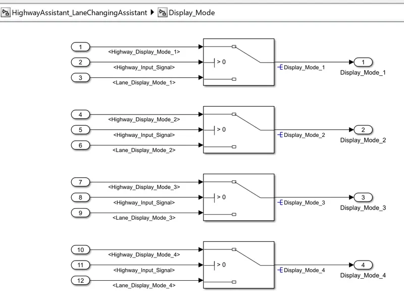
Signals coming from both subsystems “Highway_Display_Mode_1” & “Lane_Display_Mode_1” are given as inputs to a switch block which will have input signal “Highway_Input_Signal” given as 2nd input to the switch block. Corresponding output from this particular switch block is output signal “Display_Mode_1”.
Signals coming from both subsystems “Highway_Display_Mode_2” & “Lane_Display_Mode_2” are given as inputs to a switch block which will have input signal “Highway_Input_Signal” given as 2nd input to the switch block. Corresponding output from this particular switch block is output signal “Display_Mode_2”.
Signals coming from both subsystems “Highway_Display_Mode_3” & “Lane_Display_Mode_3” are given as inputs to a switch block which will have input signal “Highway_Input_Signal” given as 2nd input to the switch block. Corresponding output from this particular switch block is output signal “Display_Mode_3”.
Signals coming from both subsystems “Highway_Display_Mode_4” & “Lane_Display_Mode_4” are given as inputs to a switch block which will have input signal “Highway_Input_Signal” given as 2nd input to the switch block. Corresponding output from this particular switch block is output signal “Display_Mode_4”.
Step2: Creation of Simulink Data Dictionary file (SLDD):
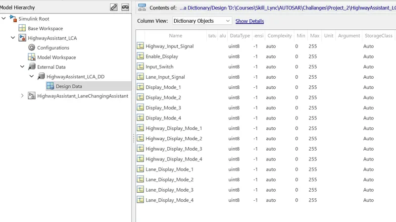
- First you go to model then click to link to data dictionary. then click the new and put the sldd file name and browse the file.after browsing the sldd file go to model worksplace and put the all input and output signal in design data box.
- A Simulink Data Dictionary (SLDD) file is created that contains input, output signals and calibration parameters used in the model. SLDD file is created by clicking on Modeling, then ‘Model Properties’, then ‘External Data’ and specifying a file name for the Data Dictionary.
Step3: Requirement Tagging
The steps involved in tagging a requirement in the Simulink model is to first highlight the requirement statement in the Word document, then right click on the subsystem in the model that has to be tagged, then select ‘Requirements’ and then ‘Link to Selection in Word’.
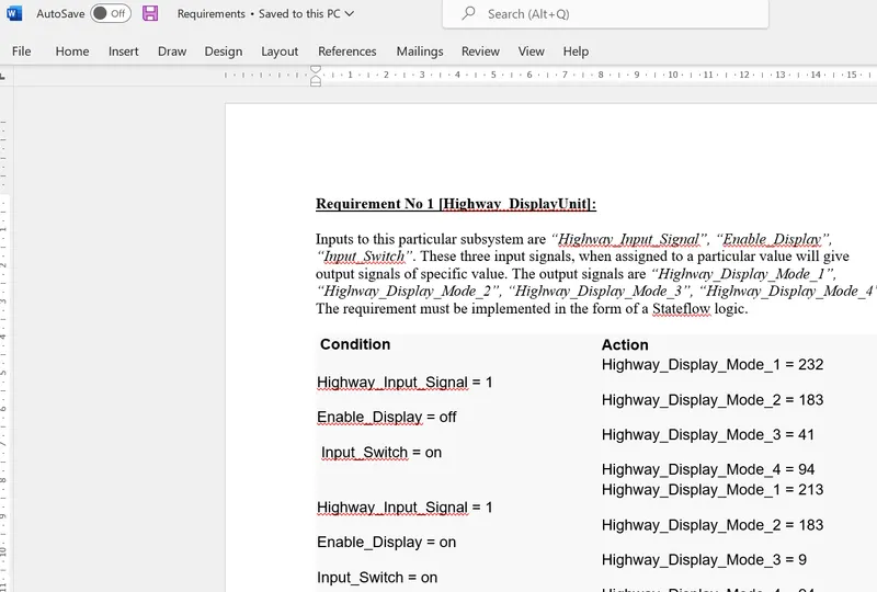
Requirement1 Tagging:
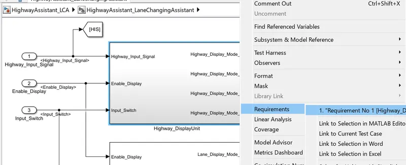
Requirement2 Tagging:
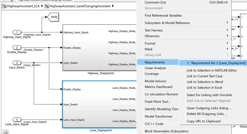
Requirement3 Tagging:
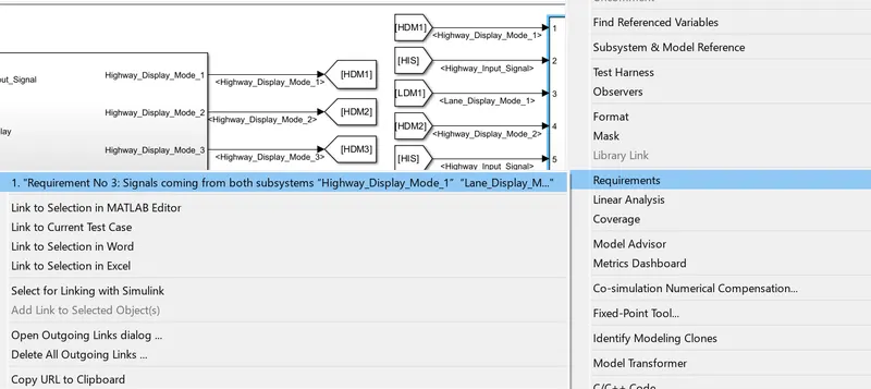
Step4: Configuration Parameter Update:
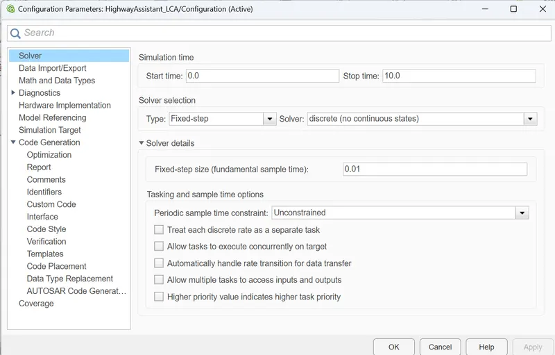
After clicking on model settings the following window will appears. The window presents the configuration of the parameters in our simulink mode.
• In the configuration window, click on solver to model the solver parameters.
• Now change the type to Fixed-step, Solver to discrete (no continuous states) and take sample time as 0.01sec.
Then click Ok.
This settings are shown in the following figure.
Model Configuration for AUTOSAR Code Generation:-
Code Generation Settings:-
1. There are mainly two settings we have to do which are solver settings and code generation settings.
2. For code ganeration we can only use a Fixed Step Solver.
3. As per requirement we can change the solver settting to Fix step discrete and Fix step size as Auto.
4. For AUTOSAR code ganeration in system Target file we always chose autosar.tlc,which is autosar component designer coder.Which generates AUTOSAR compile code.
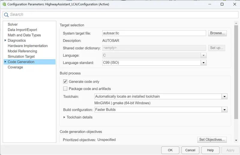
Here we select AUTOSAR system target file to generate Autosar code.
To Map Simulink model elements to AUTOSAR software component elements:
- Open a model for which AUTOSAR system Target file autosar.tlc is selected.
- Create or open a MApped view of the AUTOSAR model.In the model window,do one of the following.
- From the Apps tab,Open the AUTOSAR component designer app.
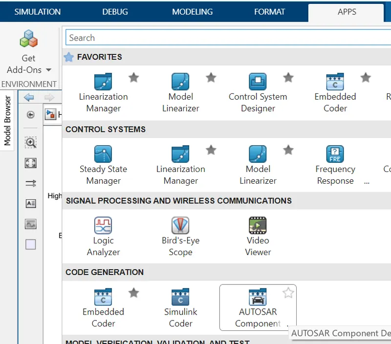
- Click the prespective control in the lower-right corner and select code.

- The following code mapping AUTOSAR software component window will open at the bottom left corner.
AUTOSAR Dictionary:-
Here we add XML options,server reciever interface,sender ports,reciever ports,and runnable one by one.
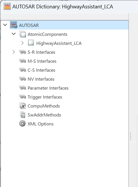
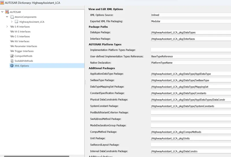
XML Options:-
Here we edit the XML options to create a data file for code gaeneration.
S-R Interface:-
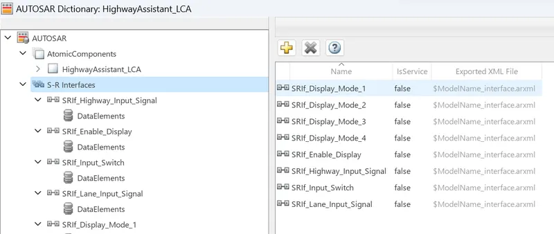
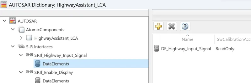
Here before creating 'inports' and 'outports'. The interface were created in order to map the inports and outports,Interfaces were Prefix SIRF_ & there corresponding Data elements were prefix DE_.
Reciever Ports:-
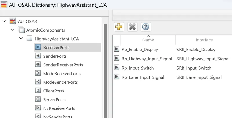
Here inports were created and input Runnables were prefix Rp_ .
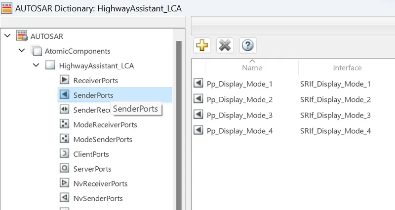
Sender Ports:-
Here outports were created and output Runnables were prefix Pp_ .
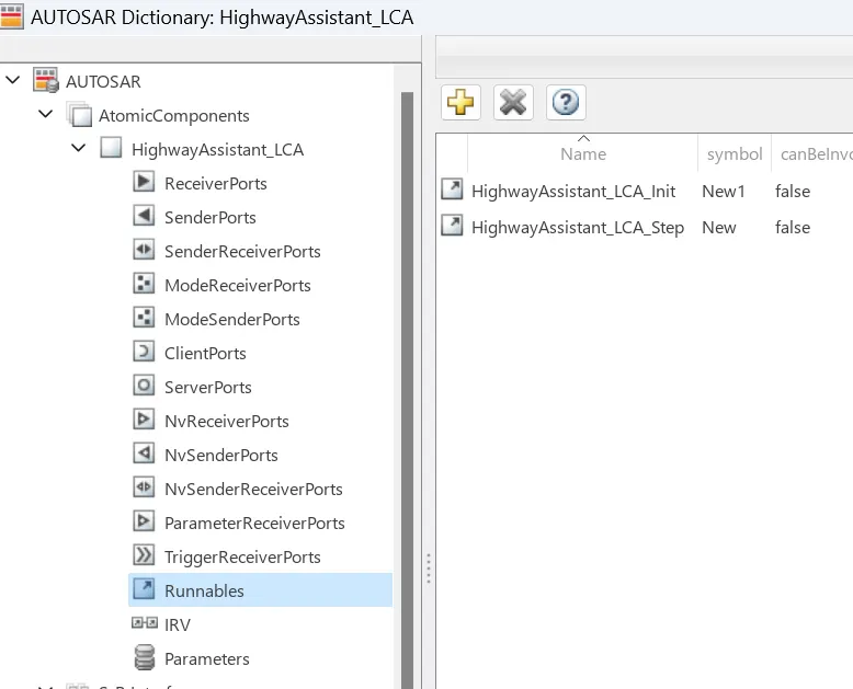
Runnables:-
Here runnables were created,one of the initializing and other for time event,event was also created as init event and TimingEvent.
Port Mapping:-
The Code Mapping editor provides incanvas access to AUTOSAR mapping information,with batch editing,element filtering,easy navigation to model elements and AUTOSAR properties,and model element traceability.
- Navigate the code Mappings editor tabs to perform these actions:
- Map a Simulink entry-point function to an AUTOSAR runnable.
- Map a Simulink inport or outport to an AUTOSAR reciever or sender port and a sender-reciever data element,with a specific data access mode.
- Map a Simulnk model workspace parameters to an AUTOSAR component parameters.
- Map a Simulink data store to an AUTOSAR variable.
- Map a Simulink block signal or state to an AUTOSAR variable.
- Map a Simulink data transfer line to an AUTOSAR inter-Runnable variable (IRV).
- Map a Simulink function caller to an AUTOSAR client port and a client-server operation.
- Use the Filter contents field (Where available) to selectively display some elements, while omiting others,in the current view.
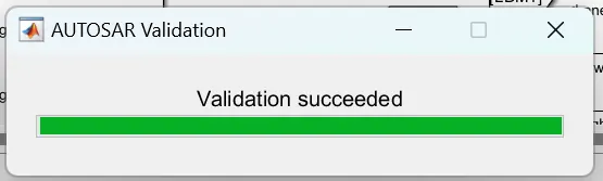
- After mapping model elements,click the validate button to validate the AUTOSAR component configuration.If errors are reported,address them and retry validation.
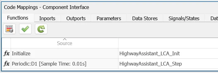
Here we select Runnables for initializing and time events.
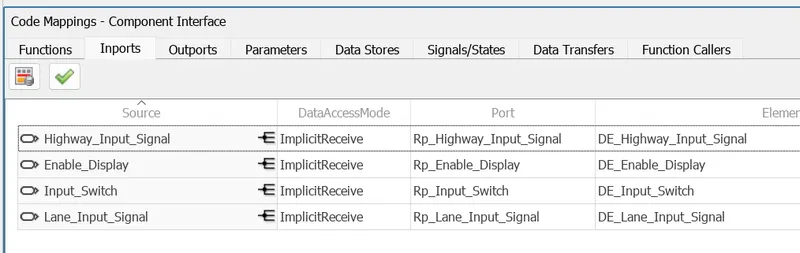
Here mapping of Inports was done with the corresponding data element.
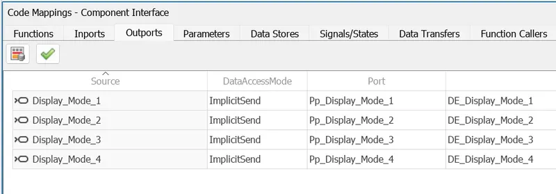
Here mapping of outports was done eith the corresponding data elements.
Here we check our mapping to see if there are any bugs. If mapping has bugs,we can solve them immediately.
Step5: MAB Guidelines Check For Model Explorer
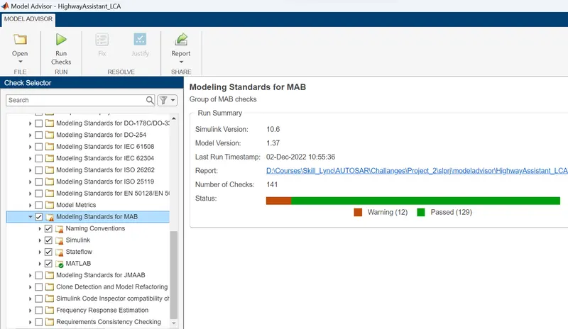
A check is performed using ‘Model Advisor’ tool in Simulink to see whether the developed model meets the modeling standards for MAB. First go to model advisor and click on ‘MAB’ then run the programme.
Step 6: AUTOSAR Quick Start
If we missed out the configuration properties and also we have to take care of all updating the signal name appropriately for that we aill do AUTOSAR quick start over here so it will list out and show any mistake apart from that this is an automated procedure to convert your model into a generated code to bypass the mannual mapping.
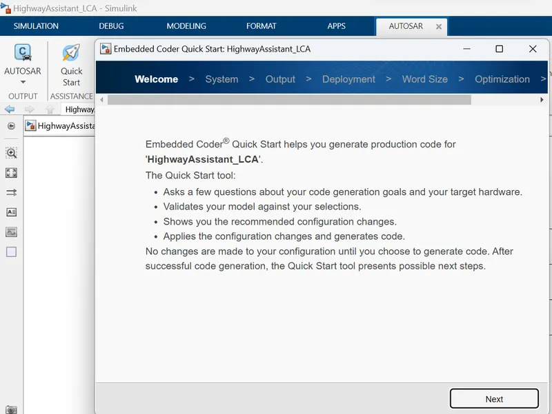
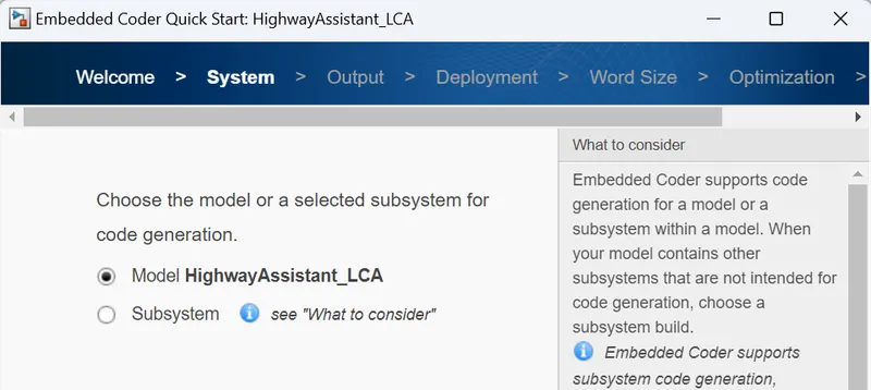
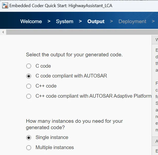
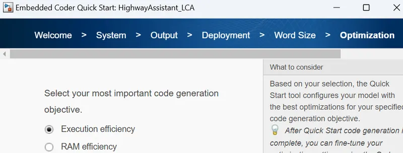
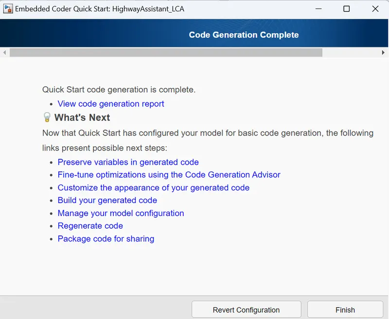
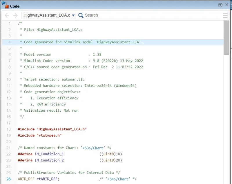
Here we got our AUTOSAR compile code for AUTOSAR software component.
Generated Code:-
/*
 * File: HighwayAssistant_LCA.c
 *
 * Code generated for Simulink model 'HighwayAssistant_LCA'.
 *
 * Model version                  : 1.38
 * Simulink Coder version         : 9.8 (R2022b) 13-May-2022
 * C/C++ source code generated on : Fri Dec  2 11:03:52 2022
 *
 * Target selection: autosar.tlc
 * Embedded hardware selection: Intel->x86-64 (Windows64)
 * Code generation objectives:
 *    1. Execution efficiency
 *    2. RAM efficiency
 * Validation result: Not run
 */

#include "HighwayAssistant_LCA.h"
#include "rtwtypes.h"

/* Named constants for Chart: '<S3>/Chart' */
#define IN_Condition_1                 ((uint8)1U)
#define IN_Condition_2                 ((uint8)2U)

/* PublicStructure Variables for Internal Data */
ARID_DEF rtARID_DEF;                   /* '<S4>/Chart' */

/* Model step function */
void New(void)
{
  sint32 rtb_Highway_Display_Mode_1;
  sint32 rtb_Highway_Display_Mode_3;
  sint32 rtb_Lane_Display_Mode_1;
  sint32 rtb_Lane_Display_Mode_2;
  sint32 rtb_Lane_Display_Mode_3;
  sint32 rtb_Lane_Display_Mode_4;
  sint32 tmp_0;
  uint8 tmp;

  /* Chart: '<S3>/Chart' incorporates:
   *  Inport: '<Root>/Enable_Display'
   *  Inport: '<Root>/Highway_Input_Signal'
   *  Inport: '<Root>/Input_Switch'
   */
  if (rtARID_DEF.is_active_c3_HighwayAssistant_L == 0U) {
    rtARID_DEF.is_active_c3_HighwayAssistant_L = 1U;
    rtARID_DEF.is_c3_HighwayAssistant_LCA = IN_Condition_1;
    rtb_Highway_Display_Mode_1 = 232;
    rtb_Highway_Display_Mode_3 = 41;
  } else if (rtARID_DEF.is_c3_HighwayAssistant_LCA == IN_Condition_1) {
    rtb_Highway_Display_Mode_1 = 232;
    rtb_Highway_Display_Mode_3 = 41;
    if ((Rte_IRead_HighwayAssistant_LCA_Step_Rp_Highway_Input_Signal_DE_Highway_Input_Signal
         () == 1) &&
        (Rte_IRead_HighwayAssistant_LCA_Step_Rp_Enable_Display_DE_Enable_Display
         () == 1) &&
        (Rte_IRead_HighwayAssistant_LCA_Step_Rp_Input_Switch_DE_Input_Switch() ==
         1)) {
      rtARID_DEF.is_c3_HighwayAssistant_LCA = IN_Condition_2;
      rtb_Highway_Display_Mode_1 = 213;
      rtb_Highway_Display_Mode_3 = 9;
    }
  } else {
    /* case IN_Condition_2: */
    rtb_Highway_Display_Mode_1 = 213;
    rtb_Highway_Display_Mode_3 = 9;
    if ((Rte_IRead_HighwayAssistant_LCA_Step_Rp_Highway_Input_Signal_DE_Highway_Input_Signal
         () == 1) &&
        (Rte_IRead_HighwayAssistant_LCA_Step_Rp_Enable_Display_DE_Enable_Display
         () == 0) &&
        (Rte_IRead_HighwayAssistant_LCA_Step_Rp_Input_Switch_DE_Input_Switch() ==
         1)) {
      rtARID_DEF.is_c3_HighwayAssistant_LCA = IN_Condition_1;
      rtb_Highway_Display_Mode_1 = 232;
      rtb_Highway_Display_Mode_3 = 41;
    }
  }

  /* End of Chart: '<S3>/Chart' */

  /* Chart: '<S4>/Chart' incorporates:
   *  Inport: '<Root>/Enable_Display'
   *  Inport: '<Root>/Input_Switch'
   *  Inport: '<Root>/Lane_Input_Signal'
   */
  if (rtARID_DEF.is_active_c1_HighwayAssistant_L == 0U) {
    rtARID_DEF.is_active_c1_HighwayAssistant_L = 1U;
    rtARID_DEF.is_c1_HighwayAssistant_LCA = IN_Condition_1;
    rtb_Lane_Display_Mode_1 = 132;
    rtb_Lane_Display_Mode_2 = 185;
    rtb_Lane_Display_Mode_3 = 54;
    rtb_Lane_Display_Mode_4 = 67;
  } else if (rtARID_DEF.is_c1_HighwayAssistant_LCA == IN_Condition_1) {
    rtb_Lane_Display_Mode_1 = 132;
    rtb_Lane_Display_Mode_2 = 185;
    rtb_Lane_Display_Mode_3 = 54;
    rtb_Lane_Display_Mode_4 = 67;
    if ((Rte_IRead_HighwayAssistant_LCA_Step_Rp_Lane_Input_Signal_DE_Lane_Input_Signal
         () == 6) &&
        (Rte_IRead_HighwayAssistant_LCA_Step_Rp_Enable_Display_DE_Enable_Display
         () == 1) &&
        (Rte_IRead_HighwayAssistant_LCA_Step_Rp_Input_Switch_DE_Input_Switch() ==
         1)) {
      rtARID_DEF.is_c1_HighwayAssistant_LCA = IN_Condition_2;
      rtb_Lane_Display_Mode_1 = 127;
      rtb_Lane_Display_Mode_2 = 248;
      rtb_Lane_Display_Mode_3 = 186;
      rtb_Lane_Display_Mode_4 = 84;
    }
  } else {
    /* case IN_Condition_2: */
    rtb_Lane_Display_Mode_1 = 127;
    rtb_Lane_Display_Mode_2 = 248;
    rtb_Lane_Display_Mode_3 = 186;
    rtb_Lane_Display_Mode_4 = 84;
    if ((Rte_IRead_HighwayAssistant_LCA_Step_Rp_Lane_Input_Signal_DE_Lane_Input_Signal
         () == 6) &&
        (Rte_IRead_HighwayAssistant_LCA_Step_Rp_Enable_Display_DE_Enable_Display
         () == 0) &&
        (Rte_IRead_HighwayAssistant_LCA_Step_Rp_Input_Switch_DE_Input_Switch() ==
         1)) {
      rtARID_DEF.is_c1_HighwayAssistant_LCA = IN_Condition_1;
      rtb_Lane_Display_Mode_1 = 132;
      rtb_Lane_Display_Mode_2 = 185;
      rtb_Lane_Display_Mode_3 = 54;
      rtb_Lane_Display_Mode_4 = 67;
    }
  }

  /* End of Chart: '<S4>/Chart' */

  /* Switch: '<S2>/Switch' incorporates:
   *  Inport: '<Root>/Highway_Input_Signal'
   *  Switch: '<S2>/Switch1'
   *  Switch: '<S2>/Switch2'
   *  Switch: '<S2>/Switch3'
   */
  tmp_0 =
    Rte_IRead_HighwayAssistant_LCA_Step_Rp_Highway_Input_Signal_DE_Highway_Input_Signal
    ();
  if (tmp_0 > 0) {
    tmp = (uint8)rtb_Highway_Display_Mode_1;
  } else {
    tmp = (uint8)rtb_Lane_Display_Mode_1;
  }

  /* Outport: '<Root>/Display_Mode_1' incorporates:
   *  Switch: '<S2>/Switch'
   */
  Rte_IWrite_HighwayAssistant_LCA_Step_Pp_Display_Mode_1_DE_Display_Mode_1(tmp);

  /* Switch: '<S2>/Switch1' */
  if (tmp_0 > 0) {
    tmp = 183U;
  } else {
    tmp = (uint8)rtb_Lane_Display_Mode_2;
  }

  /* Outport: '<Root>/Display_Mode_2' incorporates:
   *  Switch: '<S2>/Switch1'
   */
  Rte_IWrite_HighwayAssistant_LCA_Step_Pp_Display_Mode_2_DE_Display_Mode_2(tmp);

  /* Switch: '<S2>/Switch2' */
  if (tmp_0 > 0) {
    tmp = (uint8)rtb_Highway_Display_Mode_3;
  } else {
    tmp = (uint8)rtb_Lane_Display_Mode_3;
  }

  /* Outport: '<Root>/Display_Mode_3' incorporates:
   *  Switch: '<S2>/Switch2'
   */
  Rte_IWrite_HighwayAssistant_LCA_Step_Pp_Display_Mode_3_DE_Display_Mode_3(tmp);

  /* Switch: '<S2>/Switch3' */
  if (tmp_0 > 0) {
    tmp = 94U;
  } else {
    tmp = (uint8)rtb_Lane_Display_Mode_4;
  }

  /* Outport: '<Root>/Display_Mode_4' incorporates:
   *  Switch: '<S2>/Switch3'
   */
  Rte_IWrite_HighwayAssistant_LCA_Step_Pp_Display_Mode_4_DE_Display_Mode_4(tmp);
}

/* Model initialize function */
void New1(void)
{
  /* (no initialization code required) */
}

/*
 * File trailer for generated code.
 *
 * [EOF]
 */
Conclusion:-
A model is developed in MATLAB Simulink for implementing a specific portion of the 'Highway Assistant-Lane Changing Assistant' feature as per Model-Based Design (MBD) guidelines.
Simulink Data Dictionary (SLDD) is created and linked to the model.
All input & output signals used in the developed model are mapped to their corresponding S-R Interfaces in the AUTOSAR editor.
Model Advisor check is done for MAAB guidelines, followed by code generation using AUTOSAR coder for the developed model.
The code generation for model-based development is very easy compare to writing millions of codes.It will possible with right solver and code generation setting and maily due to Model Advisor check for standard MAb guidelines.
Hence,we can conclude that with proper settings and standard guidelines it will be very easy to build a code for the model.It will be cost efficient and a time saving method of design and development of model.It will be possible due to MATLAB.There is a lot of software for the same in the modelling environment but for better understanding and ease of use we can always prefer MATLAB.