Project 1 (Mini Project on Vehicle Direction Detection)
Mini Project on Vehicle Direction Detection
Aim:
The main objective of this project is to create to a MBD compliant MATLAB Simulink model for vehicle direction detection as per requirement specified.
Camera reads the road signs & stores into its memory with unique values for left turn, right turn & straight drive. Depending on the direction it is taking, final indication is given to the driver – as an indication if he is driving in the recommended direction or not.
Model Developement:
Step1: Requirement Analysis:
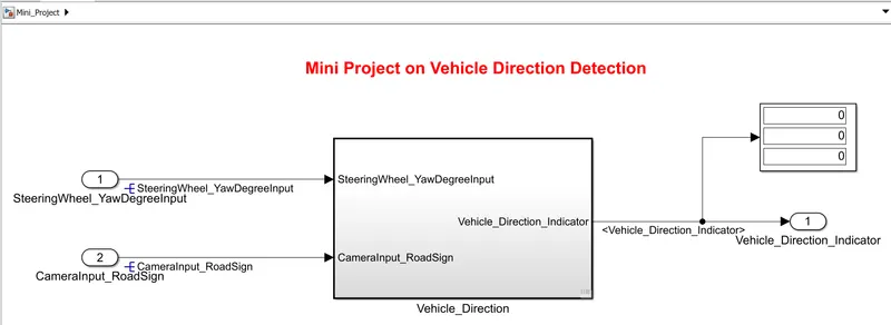
This the main model subsystem that having two inputs SteeringWheel_YawDegreeInput and CameraInput_RoadSign entering into the Vehicle Detection Determination subsystem and one output Vehicle_Direction_Indicator
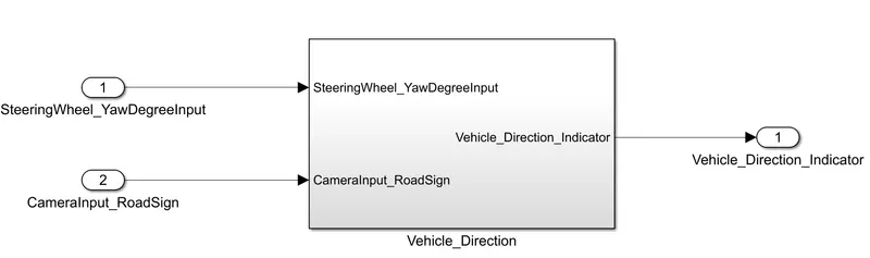
Fig 1: 'Vehicle_Direction' subsystem
There are 2 requirements are designed in two subsystem
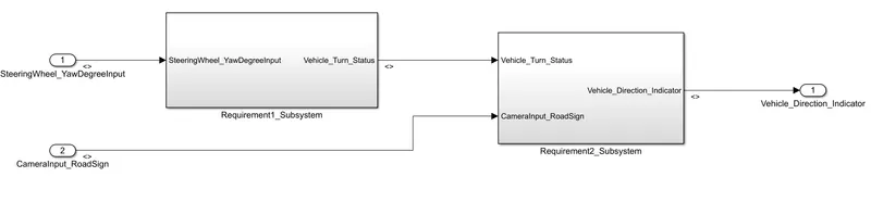
Fig 2: Requirment1 and Requirment2 Subsystem.
Requirement 1 Subsystem:
1) Vehicle_Turn_Status_Subsystem:
- Steering wheel input as yaw rate (Signal name: SteeringWheel_YawDegreeInput) is the input for this system.
- This is compared against 3 angular values, one each for left turn, right turn & straight drive (Calibration Values: Right_Turn_AngularLimit, Left_Turn_AngularLimit, Straight_Drive_Steering_Angle) to say which specific direction the steering wheel is turning towards.
- Use switch blocks to compare & develop this requirement. Keep this requirement in a subsystem & output of this requirement is a local signal (Signal Name: Vehicle_Turn_Status).
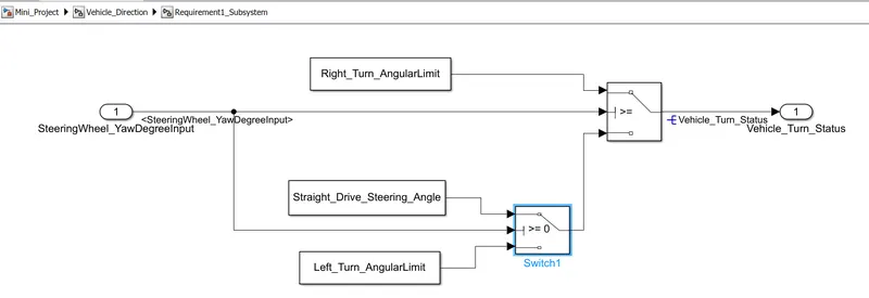
Fig 3:Requirment1Subsystem
Requirement – 2:
2)Vehicle_Direction_Indicator_Subsystem:
- Keep this requirement as a separate subsystem. Inputs to this requirement are local signal from requirement 1 (Signal Name: Vehicle_Turn_Status) & an input signal from camera (Signal Name: CameraInput_RoadSign), which confirms the occurrence of a road sign.
- Signal Vehicle_Turn_Status is compared against calibration values (Calibration Values: RightTurn_RoadSign, LeftTurn_RoadSign, Straight_RoadSign), if each of them is found equal, then each of the three corresponding output is compared against the camera input signal,
- Using a logical operator block, only one among them is finally given as output signal (Signal Name: Vehicle_Direction_Indicator).
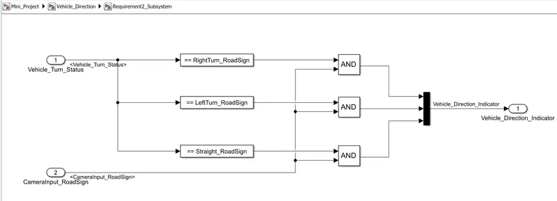
Fig 4:Requirment1Subsystem
Step2: Creation of Simulink Data Dictionary file (SLDD):
- First you go to model then click to link to data dictionary. then click the new and put the sldd file name and browse the file.after browsing the sldd file go to model worksplace and put the all input and output signal in design data box.
- A Simulink Data Dictionary (SLDD) file is created that contains input, output signals and calibration parameters used in the model. SLDD file is created by clicking on Modeling, then ‘Model Properties’, then ‘External Data’ and specifying a file name for the Data Dictionary.
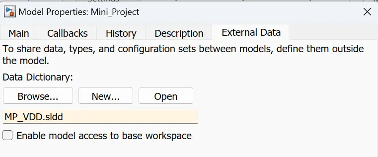
Fig 5:Simulink Data Dictionary Dialog box.
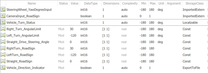
Fig 6:Model workspace sldd Design data file
Step3: Requirement Tagging
The requirements ‘Requirement-1’ and ‘Requirement-2’ as provided in the Requirements Word document are tagged to their corresponding subsystem in the Simulink Model.
The steps involved in tagging a requirement in the Simulink model is to first highlight the requirement statement in the Word document, then right click on the subsystem in the model that has to be tagged, then select ‘Requirements’ and then ‘Link to Selection in Word’.
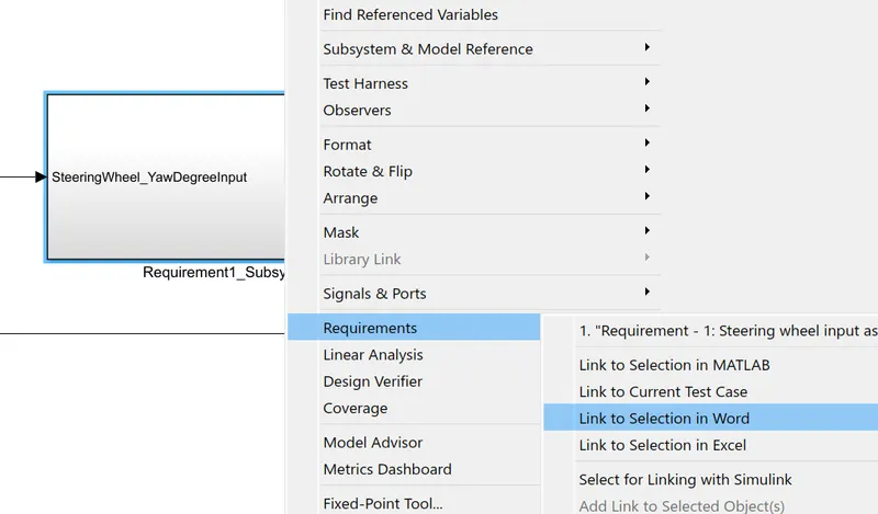
Fig:7 Requirement Tagging Requirement1 word file:
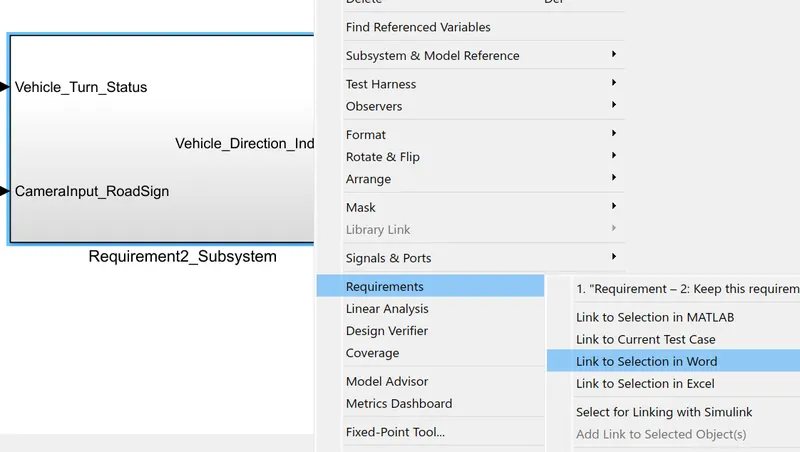
Fig:8 Requirement Tagging Requirement2 word file
Step4: MAB Guidelines Check For Model Explorer:
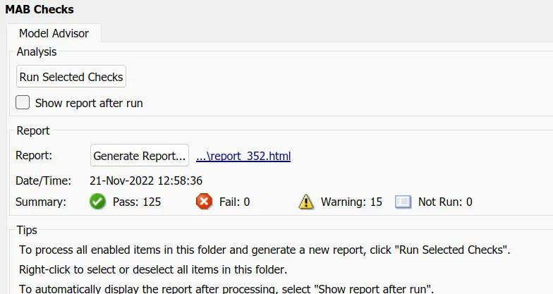
A check is performed using ‘Model Advisor’ tool in Simulink to see whether the developed model meets the modeling standards for MAB. First go to model advisor and click on ‘MAB’ then run the programme.
Step5: Embedded Coder (Code Generation)
Using embedded coder convert the simulnik model as a ‘c code’ file. This file is code generation file.
Go to embedded coder then click on building option. Then c code file automatically was created.
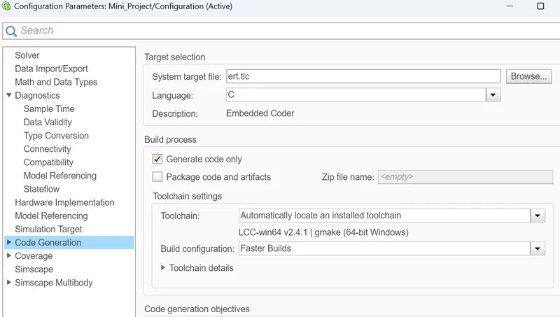
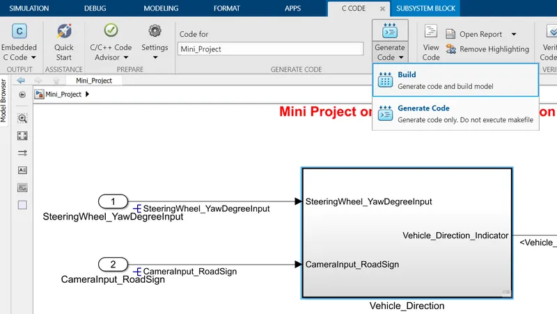
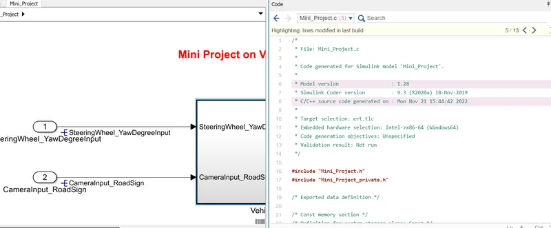
Fig 9: C Code file(using Embedded coder)
Results & Conclusion:
The vehicle direction determination is modelled as per the requirement, All the signals are defined in Simulink data dictionary. All input and output signals are resolved and propagated. Updated the model to check for static errors. Run the model advisor tool to see any errors. since there are no errors in Model Advisor Report. Code has been generated using Embedded Coder.
With reference to attached test cases, After running the simulation, we can clearly see that the vehicle is moving the straight direction.
As the output is boolean, If we get the output as (0,0,1), Then the vehicle is moving in the straight drive.
If the output as (1,0,0), Then the vehicle is taking in the Right turn.
If the output is (0,1,0), Then the vehicle is taking the Left turn.
Autonomous vehicles consists of various Advance Driver-Assistance System (ADAS) features. Vehicle Driection Detection is one the features of the vehicles.
Hence, created an Simulink model of Vehicle Direction Detection as per the Requirement data.