Project 2 - Development of TFT Cluster Speedometer Software Component
The Cluster ECU (Electronic Control Unit) in a vehicle plays a crucial role in managing and displaying important information to the driver. It serves as a central hub for receiving and processing signals from various sources, including other ECUs through the CAN bus interface and commands from the driver via steering wheel buttons. Here's a breakdown of its functions:
-
Signal Reception: The Cluster ECU is equipped with a CAN bus interface that allows it to receive signals and data from other Electronic Control Units (ECUs) within the vehicle. These signals can include information related to engine status, vehicle speed, fuel level, temperature, and various other parameters.
-
Driver Interaction: The Cluster ECU interfaces with the driver through steering wheel buttons and other input devices. These buttons are typically used for controlling various vehicle functions, such as adjusting audio settings, navigating through menus, and activating cruise control.
-
Signal Processing: Once the Cluster ECU receives signals from the CAN bus and driver commands, it processes this data. The processing may involve interpreting the data, performing calculations or conversions, and determining how to present the information to the driver effectively.
-
Information Display: One of the primary functions of the Cluster ECU is to display essential vehicle information to the driver. This information is often presented on an LCD screen, which can show details like vehicle speed, RPM, fuel level, temperature, navigation directions, and more. The Cluster ECU is responsible for formatting and updating this information in real-time.
-
Warning Indicators: In addition to displaying standard information, the Cluster ECU is also responsible for illuminating warning indicators, such as check engine lights, low fuel warnings, and other alerts. These indicators are crucial for informing the driver of potential issues or safety concerns.
-
Customization and Personalization: Some Cluster ECUs allow drivers to customize the information displayed on the LCD screen or adjust settings according to their preferences. This personalization can enhance the driving experience.
-
Integration: The Cluster ECU needs to coordinate with other ECUs and vehicle systems to ensure the seamless functioning of all vehicle components. For example, it might work with the engine control unit (ECU) to display engine-related data accurately.
In summary, the Cluster ECU serves as a critical component for managing and conveying vehicle information to the driver. It acts as an interface between the various systems within the vehicle and the driver, ensuring that the driver receives accurate and relevant information while also allowing for control and customization of certain vehicle functions.
TFT Cluster Speedometer Software Component:
Requirement 1:- Input_Processing
Average Vehicle Speed would be displayed only if its between 2 kmph & 250 kmph. Any value outside this range will be discarded by its lower limit & upper limit
When Average Vehicle Speed is < 2 xss=removed>
When Average Vehicle Speed is in between 2 kmph & 250 kmph, Display Speed = Average Vehicle Speed
When Average Vehicle Speed is > 250 kmph, Display Speed = 250 kmph
Requirement 2:- Main_Data_Filtering
Main Data Filtering subsystem will be activated for every 10th millisecond
DisplaySpeed1 (t) = ((DisplaySpeed (t) x 0.65)/ Main Filter Speed Value) - 0.05
Requirement 3:- Auxillary Data Filtering
Auxillary Data Filtering subsystem will be activated for every 10th millisecond
DisplaySpeed_Filter (t) = ((DisplaySpeed1 (t) x 0.78)/ Auxillary Filter Speed Value) - 0.03
Requirement4:- TFT Speed Output:-
If |(DisplaySpeedFilter - DisplaySpeed)| > 1.5
{
Vehicle Speed Display = DisplaySpeed
}
else
{
Vehicle Speed Display = DisplaySpeed Filter
}
SLDD FILE CREATE ACCORDING TO MODEL
following are pic
FINAL MODEL WITH SIGNAL RESOLVING.
Following are workflow of project
- simulink model file
- SLDD file
- requirement tagging report
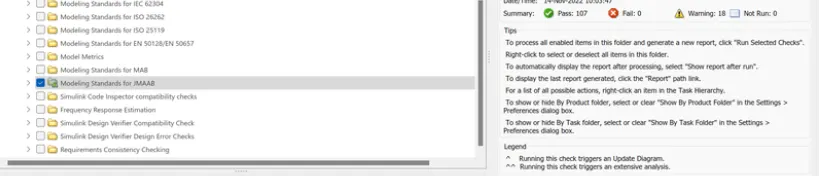
- model advisor JMAAB
- fixed-point tool
- SLDV design error detection report
- functional test MIL,SIL harness,coverage reports
- SLDV test genration report
- Auto code generation report,main,c&h files
- polyspace analysis report/output
- Test manager report-baseline& back to back testing
requirement tagging report
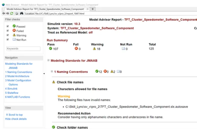
model advisor JMAAB report
report
- fixed-point tool-test
before apply the fixed point tool box
prepare result
Collect_ranges
apply data types
- SLDV design error detection report
- SLDV test genration report
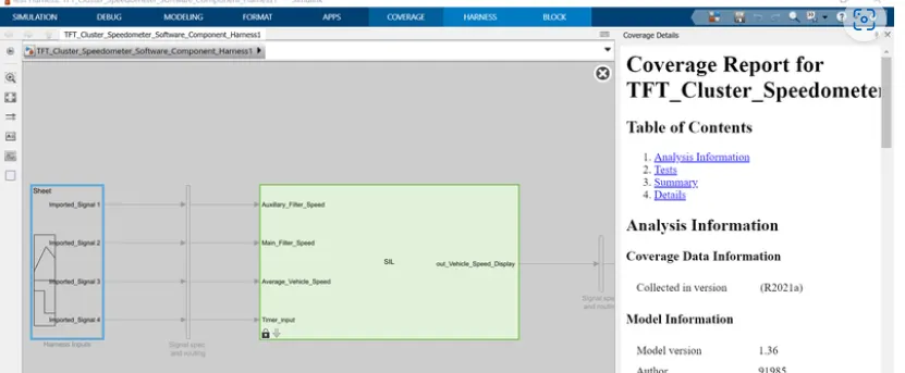
- functional test MIL,SIL harness,coverage reports
test cases upload
MIL test templates
coverage reports
Auto_code_generation
SIL harness templates and coverage analysis report
polyspace report
9. Poly space analysis report / outputs
Steps to create a Polyspace Report:
- Initially, open the Polyspace in that new project click on start new project.
- The Project Properties dialogue box will open in that give the project name as we saved in the MATLAB,then select the location where it we need to save after that click Next or use the default location.
- Then ,it asks for the Projrct source,click on browserand select the folder where th .c file are generated then optionally we can add the include folder then clock on finish,the polyspace environment will open.
- In the configuraton settings option called Target & compiler select the source code language as c,change the target processor as X86_64.
- In the coding standards & code Metrics in that enable the check MISRA C:2004 also select the calculate the code metrics option
- After that go to bug finder analysis under that select the default one.
- Go to reporting enable the generate report option and ouput formet as PDF or any file we need
- Finally save the polyspace and run the Bug Finder.
10)Test manager report-baseline& back to back testing
here showed difference"zero"
Key Takeaways:
-
The software component of the TFT Cluster Speedometer is designed to ensure accurate and reliable display of vehicle speed.
-
Extensive testing, analysis, and validation are performed to ensure the software's quality and reliability.
-
Reports are generated at various stages of the development process to document progress and identify any issues or discrepancies.
-
The project follows industry standards and guidelines, such as MISRA C:2004 and JMAAB, to maintain code quality and safety.
-
The Polyspace analysis helps in identifying and addressing potential code defects and vulnerabilities.
-
The Test Manager report assesses the testing process, highlighting any differences between baseline and back-to-back testing and providing insights into the exercise's outcomes.
Overall, this project involves meticulous software development, testing, and reporting processes to ensure that the TFT Cluster Speedometer functions correctly and meets quality and safety standards.