Project 2 - Development of TFT Cluster Speedometer Software Component
-Development of TFT Cluster Speedometer Software Component.
-Cluster Instrument receives the signals from other ECU via CAN bus interface. It also receives commands from the driver via steering wheel buttons. The signals are then processed by the Cluster ECU, after which the Cluster ECU may send the vehicle information to the LCD or light the LEDs and so forth, according to the results. Therefore, the Cluster ECU can be viewed as a carrier of the information flow.
-Requirements:
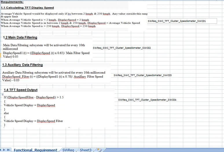
1.1 Calculating TFT Display Speed
|
Average Vehicle Speed would be displayed only if its between 2 kmph & 250 kmph. Any value outside this range will be discarded by its lower limit & upper limit |
|
When Average Vehicle Speed is < 2 kmph, DisplaySpeed = 2 kmph |
|
When Average Vehicle Speed is in between 2 kmph & 250 kmph, DisplaySpeed = Average Vehicle Speed |
|
When Average Vehicle Speed is > 250 kmph, DisplaySpeed = 250 kmph |
1.2 Main Data Filtering
|
Main Data Filtering subsystem will be activated for every 10th millisecond |
||||||
|
DisplaySpeed1 (t) = ((DisplaySpeed (t) x 0.65)/ Main Filter Speed Value) 0.05 |
1.3 Auxiliary Data Filtering
|
Auxiliary Data Filtering subsystem will be activated for every 10th millisecond |
|||||||
|
DisplaySpeed_Filter (t) = ((DisplaySpeed1 (t) x 0.78)/ Auxillary Filter Speed Value) - 0.03 |
1.4 TFT Speed Output
|
If |(DisplaySpeedFilter - DisplaySpeed)| > 1.5 |
|
{ |
|
Vehicle Speed Display = DisplaySpeed |
|
} |
|
else |
|
{ |
|
Vehicle Speed Display = DisplaySpeed Filter |
|
} |
-1)Simulink Model File:
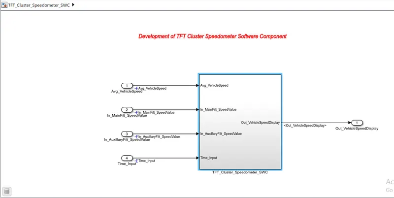
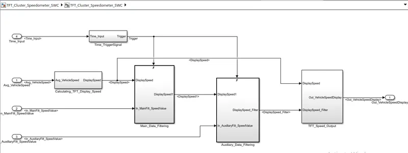
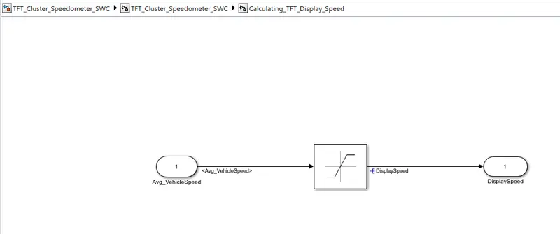
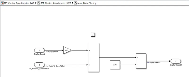
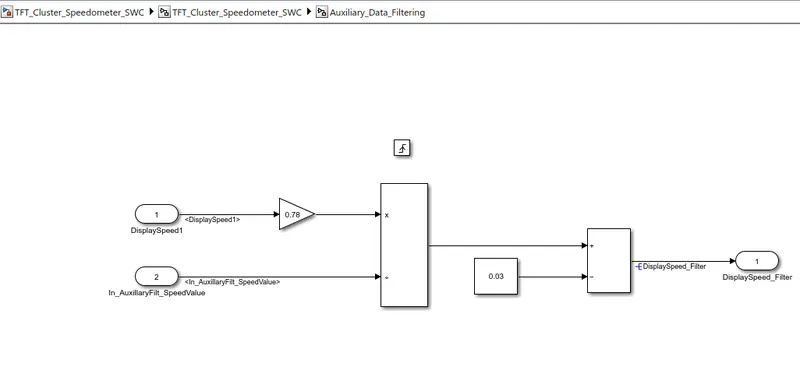
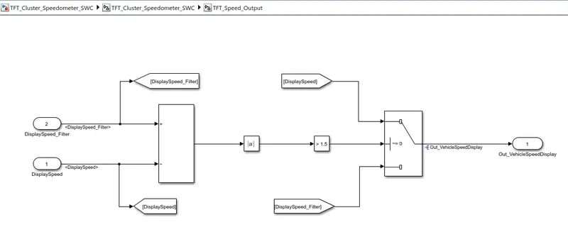
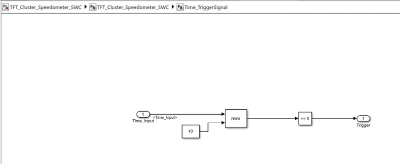
2)SLDD File:
-Create the SLDD File;
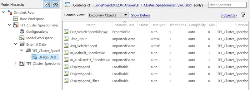
3)Requirement Tagging Report:
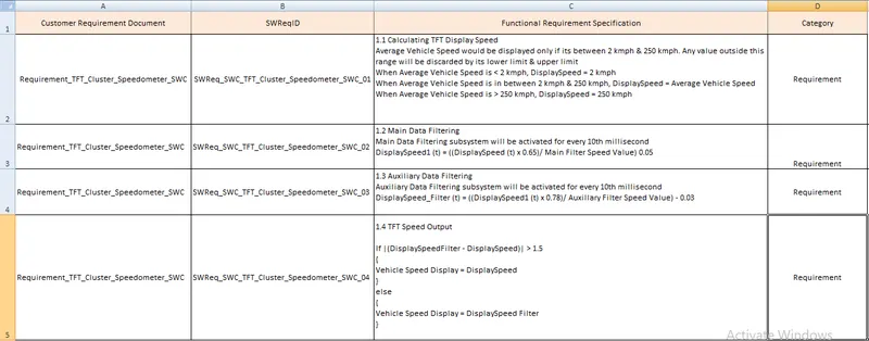
-Create the functional and SWReq file into the .xls File;
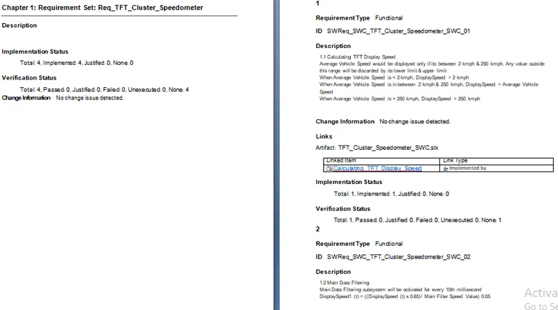
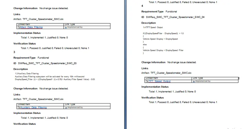
-Linking the Requirement to the model using Requirement Editor:(Report)
4)Fixed-point Tool:
-Run the Model error free>>Click on 'Fixed-point Tool' app>>Click on 'New'>>Click on Iterative Fixed-point conversion;
-SLDD Before applying Fixed-point Tool;
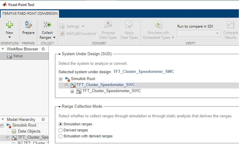
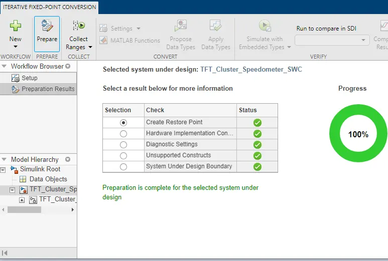
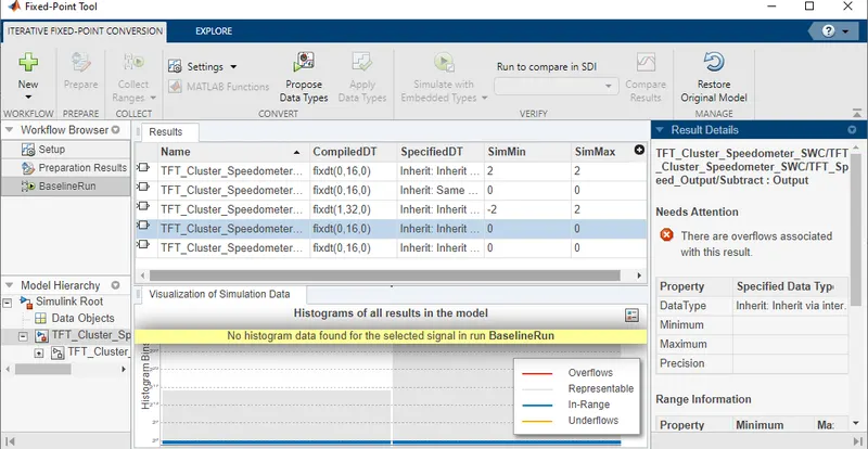
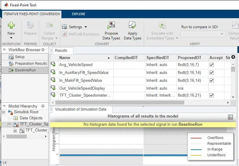
-Then click on 'Prepare' then click on 'collect Ranges'>>then Click on 'Propose Data Type>>click on 'Apply Data Type;
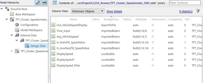
-SLDD After Fixed-point Tool Applying:
5)Model advisor-JMAAB Compliance Report:
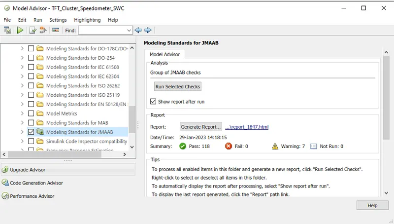
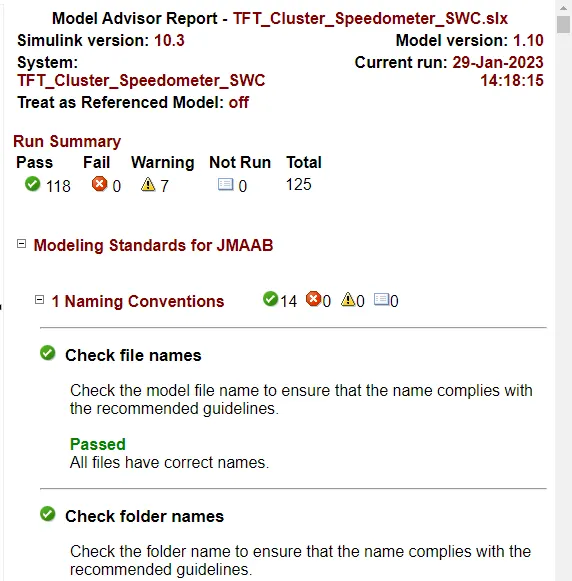
-Open the Model into the Simulink editor tab and Click on 'model advisor'>>select'Modeling standards for JMAAB and click on 'Run selected check';
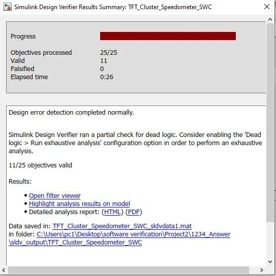
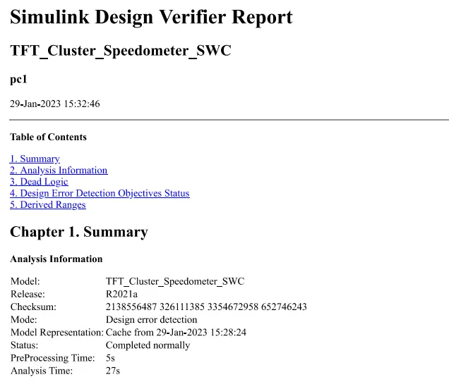
6)SLDV Design Error Detection Report:
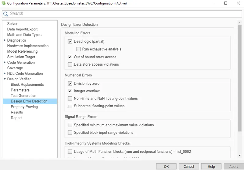
-Go to the model>>open the 'Design verifier' app>>Select 'design error Detection'>>'then Error detection setting'>>ckeack for 'compatibility'>>Click on 'Detect design Errors;
-Report:
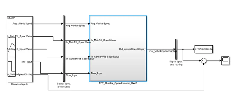
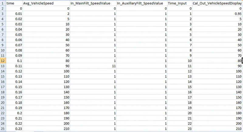
7)Functional test case,MIL & SIL harness, Coverage reports:
-Simulink Model;
-MIL Model;
-Functional test cases;
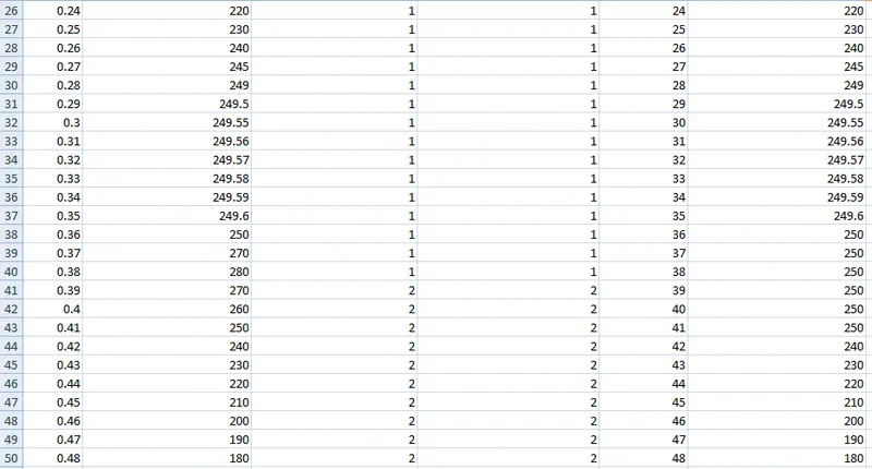
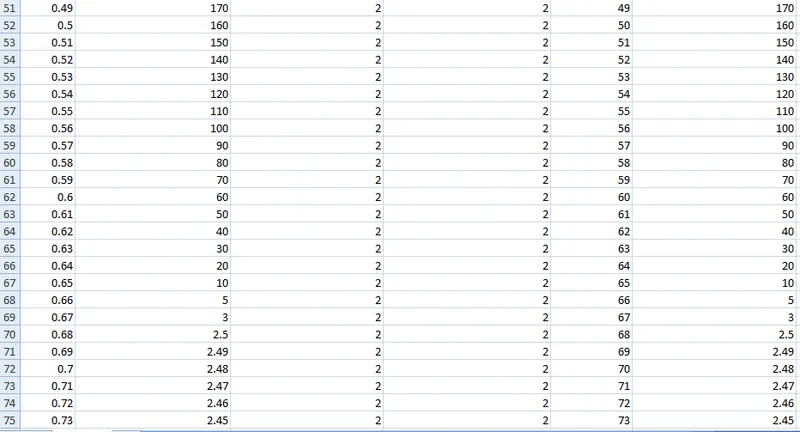
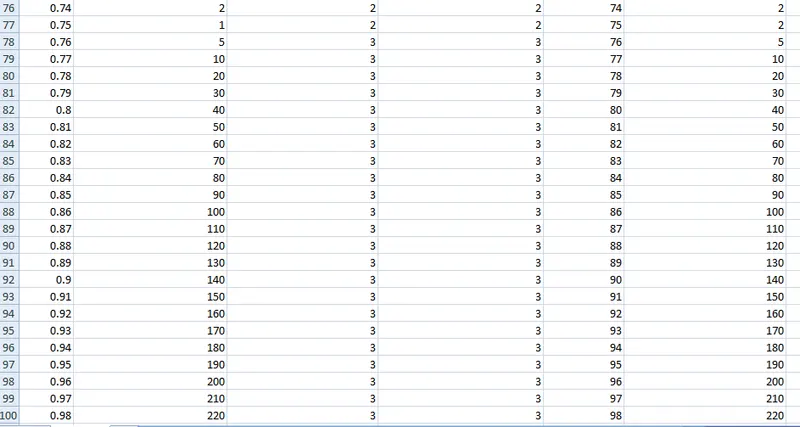

-Signal builder input signal;
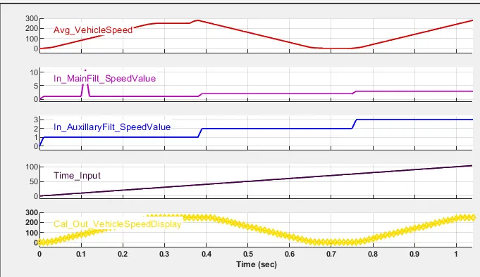
-Data Inspector Output;
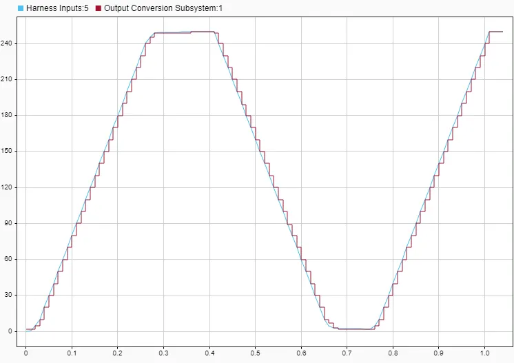
-MIL Coverage Reports;
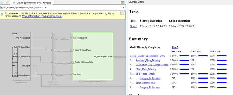
-SIL Model;
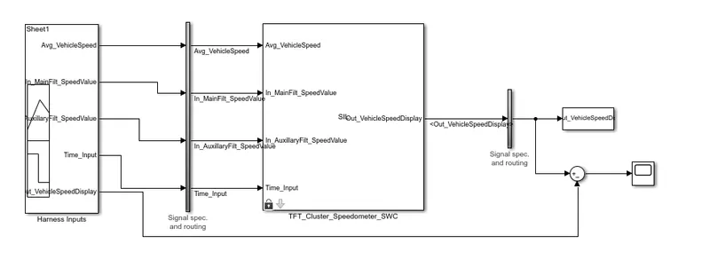
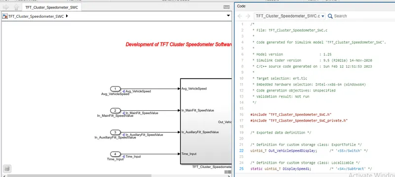
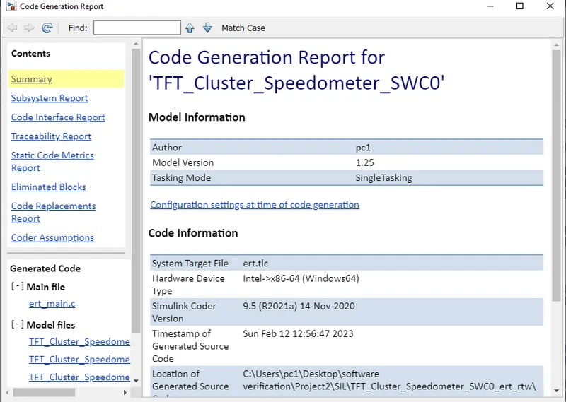
-Code Generation Report;
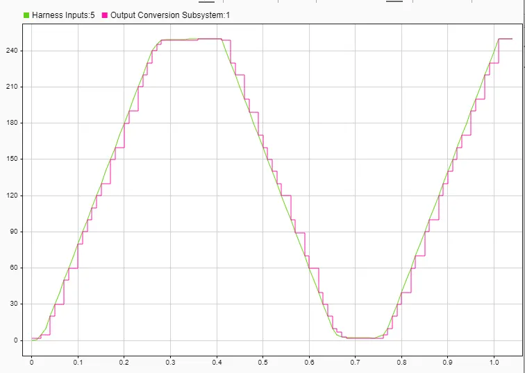
-Data Inspector Output;
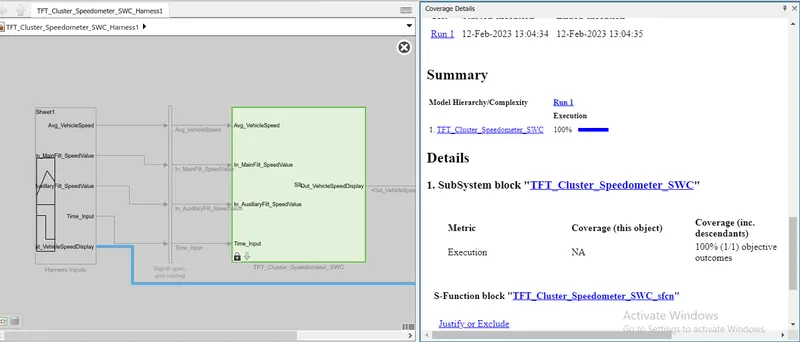
-SIL coverage Reports;
8)SLDV Test Generation Reports:
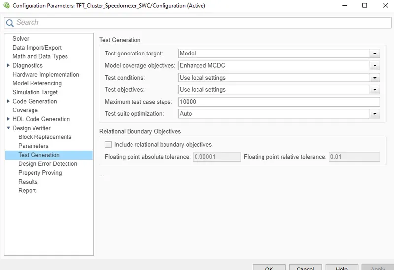
-Open the model>>Select 'Test Generation'>>Then 'Test generation setting'>> 'Advisor'>>Then 'Generate Test';
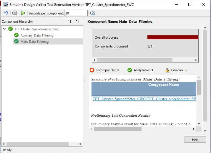
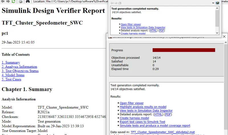
-Report;
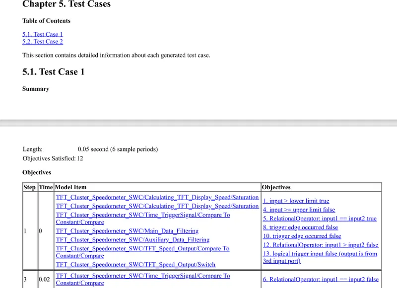
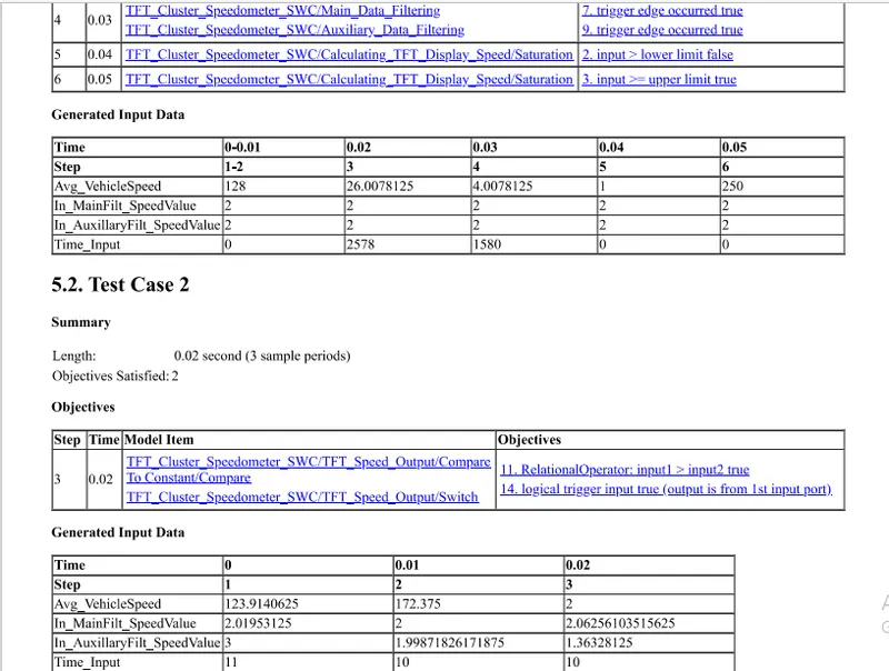
9)Auto-code Generation Report, Main .c & .h file:
-Open the model >>Model setting and make Code generation setting as 'embedded c' and make'treat as atomic subsystem'>>click on 'Embedded coder'>>And 'Generates code and built the models';
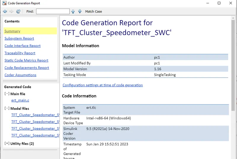
-Code Reports;
/*

 * File: TFT_Cluster_Speedometer_SWC.c

 *

 * Code generated for Simulink model 'TFT_Cluster_Speedometer_SWC'.

 *

 * Model version                  : 1.16

 * Simulink Coder version         : 9.5 (R2021a) 14-Nov-2020

 * C/C++ source code generated on : Sun Jan 29 15:52:51 2023

 *

 * Target selection: ert.tlc

 * Embedded hardware selection: Intel->x86-64 (Windows64)

 * Code generation objectives: Unspecified

 * Validation result: Not run

 */


#include "TFT_Cluster_Speedometer_SWC.h"

#include "TFT_Cluster_Speedometer_SWC_private.h"


/* Exported data definition */


/* Definition for custom storage class: ExportToFile */

uint16_T Out_VehicleSpeedDisplay;      /* '/Switch' */


/* Definition for custom storage class: Localizable */

static uint16_T DisplaySpeed1;         /* '/Subtract' */

static uint16_T DisplaySpeed_Filter;   /* '/Subtract' */


/* Previous zero-crossings (trigger) states */

PrevZCX_TFT_Cluster_Speedomet_T TFT_Cluster_Speedometer_PrevZCX;


/* Real-time model */

static RT_MODEL_TFT_Cluster_Speedome_T TFT_Cluster_Speedometer_SWC_M_;

RT_MODEL_TFT_Cluster_Speedome_T *const TFT_Cluster_Speedometer_SWC_M =

  &TFT_Cluster_Speedometer_SWC_M_;

int32_T div_s32_floor(int32_T numerator, int32_T denominator)

{

  int32_T quotient;

  uint32_T absDenominator;

  uint32_T absNumerator;

  uint32_T tempAbsQuotient;

  boolean_T quotientNeedsNegation;

  if (denominator == 0) {

    quotient = numerator >= 0 ? MAX_int32_T : MIN_int32_T;


    /* Divide by zero handler */

  } else {

    absNumerator = numerator < 0 ? ~(uint32_T)numerator + 1U : (uint32_T)

      numerator;

    absDenominator = denominator < 0 ? ~(uint32_T)denominator + 1U : (uint32_T)

      denominator;

    quotientNeedsNegation = ((numerator < 0) != (denominator < 0));

    tempAbsQuotient = absNumerator / absDenominator;

    if (quotientNeedsNegation) {

      absNumerator %= absDenominator;

      if (absNumerator > 0U) {

        tempAbsQuotient++;

      }

    }


    quotient = quotientNeedsNegation ? -(int32_T)tempAbsQuotient : (int32_T)

      tempAbsQuotient;

  }


  return quotient;

}


/* Model step function */

void TFT_Cluster_Speedometer_SWC_step(void)

{

  /* local block i/o variables */

  uint16_T DisplaySpeed;

  int32_T tmp_0;

  uint32_T tmp;

  uint16_T tmp_1;

  boolean_T rtb_Compare;


  /* Saturate: '/Saturation' incorporates:

   *  Inport: '/Avg_VehicleSpeed'

   */

  tmp = (uint32_T)Avg_VehicleSpeed << 1;

  if (tmp >= 64000U) {

    /* Saturate: '/Saturation' */

    DisplaySpeed = 64000U;

  } else if (tmp <= 512U) {

    /* Saturate: '/Saturation' */

    DisplaySpeed = 512U;

  } else {

    /* Saturate: '/Saturation' */

    DisplaySpeed = (uint16_T)(Avg_VehicleSpeed << 1);

  }


  /* End of Saturate: '/Saturation' */


  /* RelationalOperator: '/Compare' incorporates:

   *  Constant: '/Constant'

   *  Inport: '/Time_Input'

   *  Math: '/Rem'

   */

  rtb_Compare = ((uint16_T)(Time_Input % 10) == 0);
10)Poly space Analysis Report/Outputs:
-For Bug Finder;
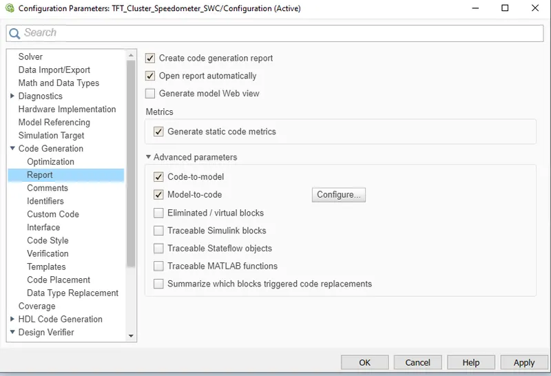
-Make code generation setting as below and built the model for code and generates the code using auto code generation;
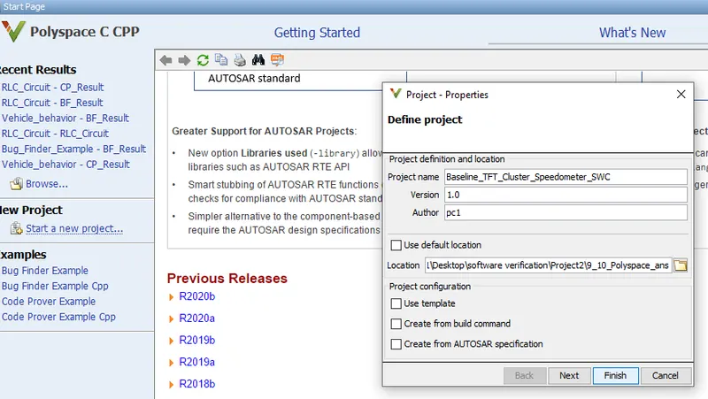
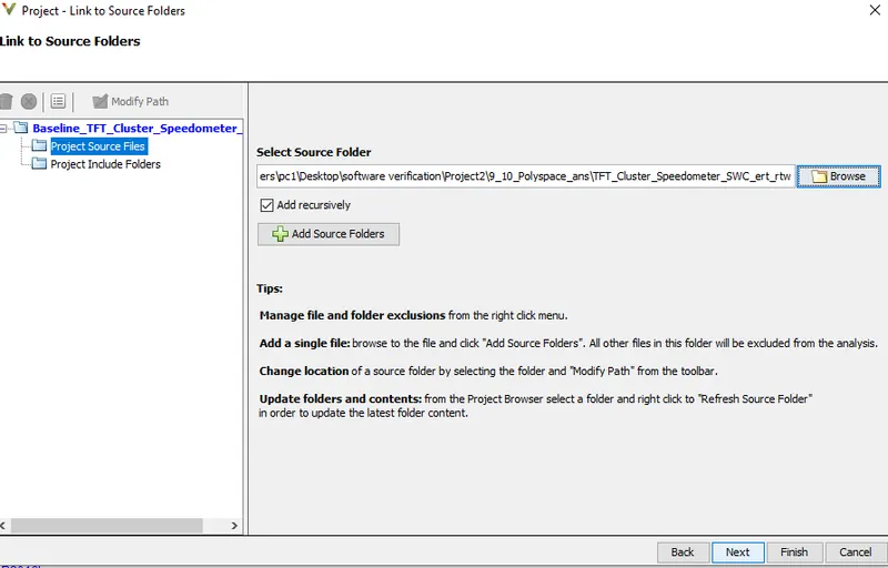
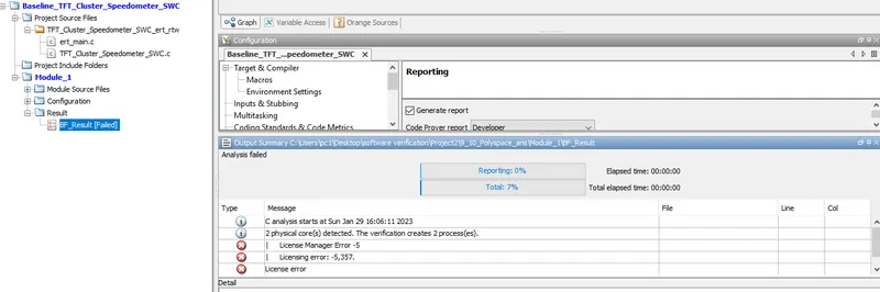
-Open the polyspace app>>Click on 'Start a New project>>Then link to a source file>>Select 'Bug Finder>>and make configuration setting as below and then save and Run Bug Finder;
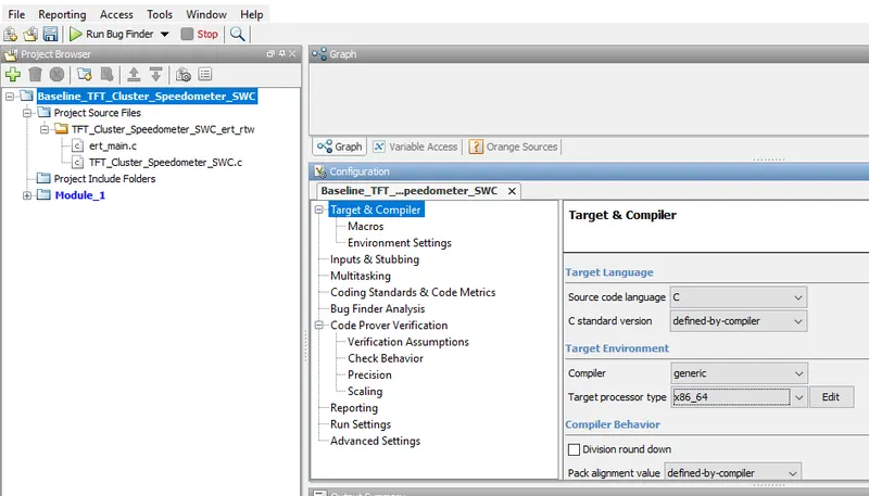
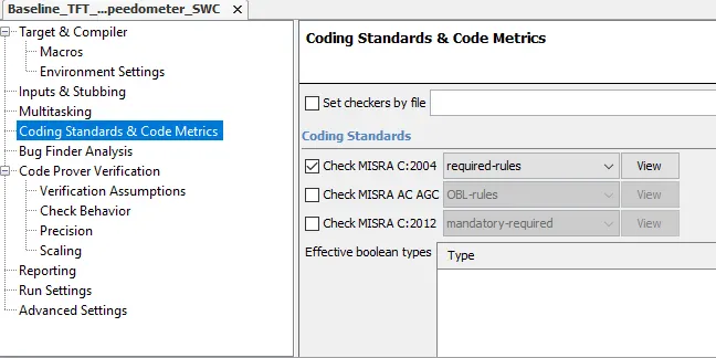
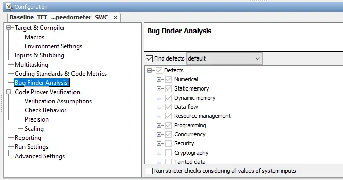
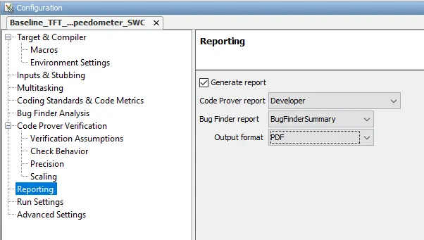
-Result:
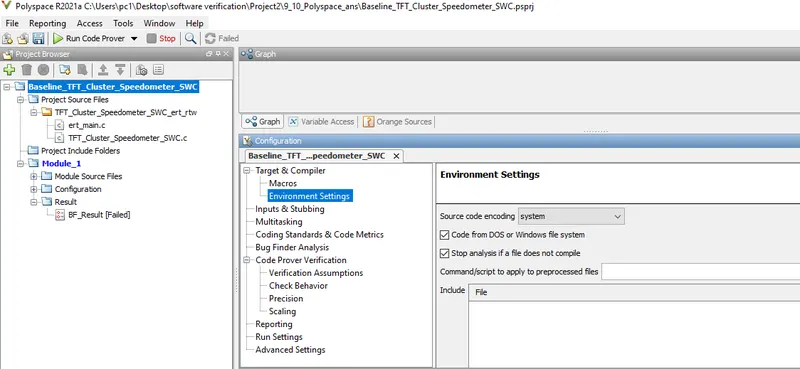
-For Code Prover;
-Keeping above setting as same and select 'Code prover' and make following configuration setting then save and Run the code prover;
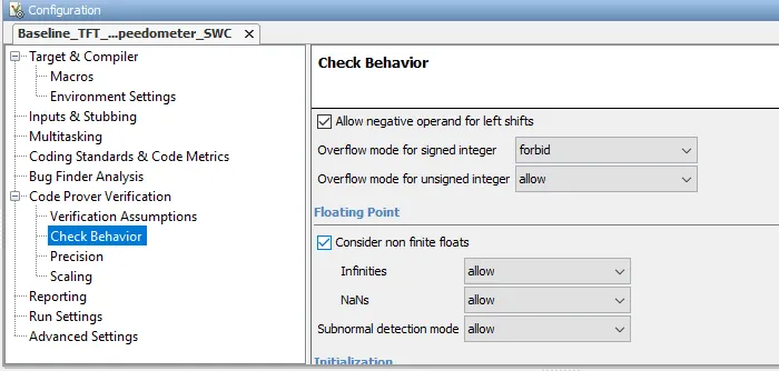
-Result:
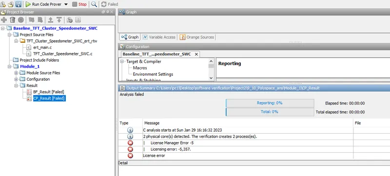
Note:Here we are not getting the proper result due to the unavailability of licence version for polyspace
11)Test Manager Reports-Baseline and Back_to_Back Testing:
-Baseline Testing;
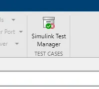
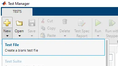
-Run Model>>Go to the simulink test manager>>Click on'New'>> test file'>>And create test name;
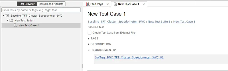
-Go to the Requirement;
-Click on 'System under test';

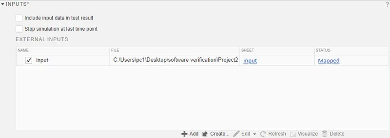
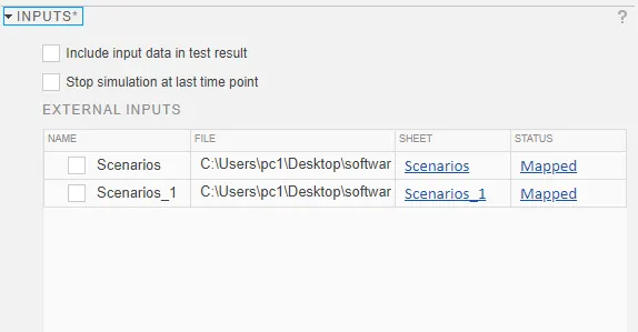
-Click on 'Input';(Input Mapping)
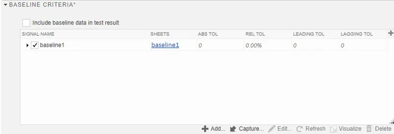
-Click on 'Baseline Criteria';
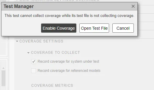
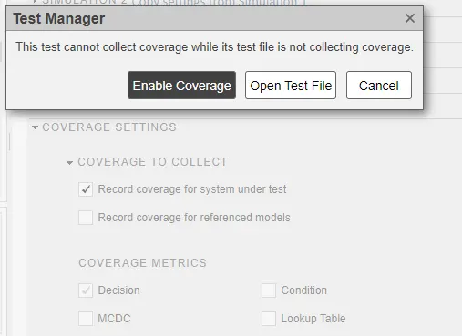
-Click on 'Coverage setting';
-Then save and Run the Test;
-Results:
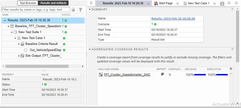
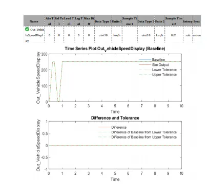
-Baseline criteria results;
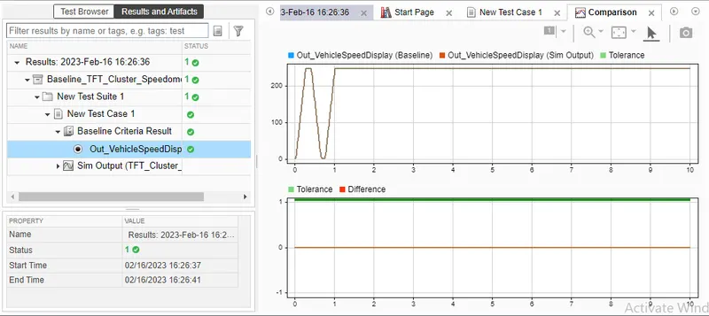
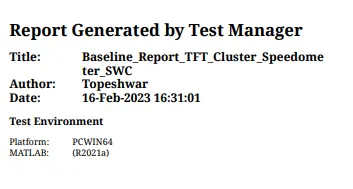
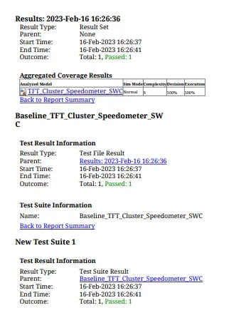
-Baseline test Result Reports;
-For Back-to-Bach Testing;
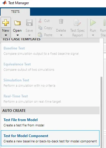
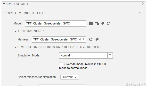
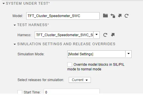
-Go to the sinulink test manager>>click on 'New'>Test file>>Again Click on 'New'>Test for model component>>Then make following settings>>Click 'Next' And 'Done' at final;
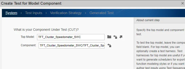
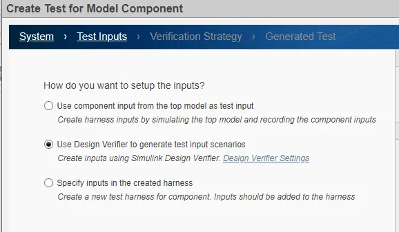
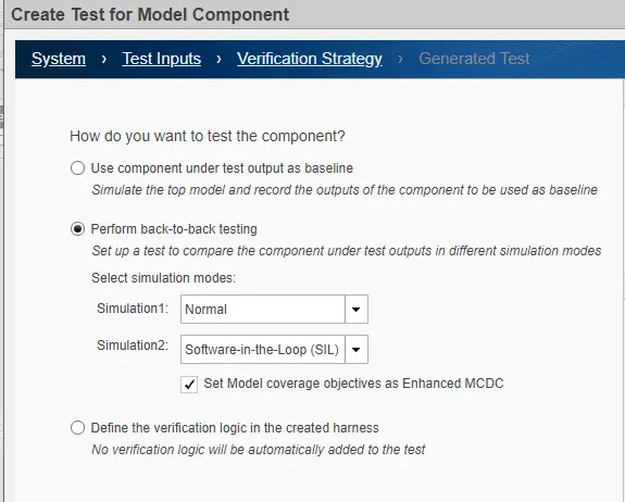
-Then select tset location and test will be generated as below,
-Generated MIL And SIL model;
-Then Go to Requirements;
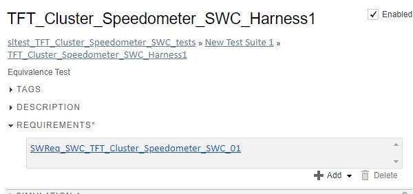
-Check Simulation1;
-Check Simulation2;
-Click On Inputs;
-Click on Coverage setting;
-Then Save and Run;
-Results;
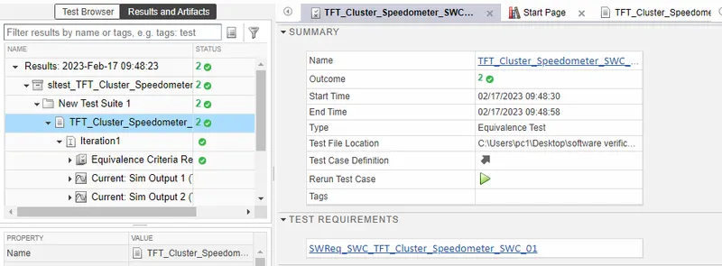
-Equivalence criteria Results;
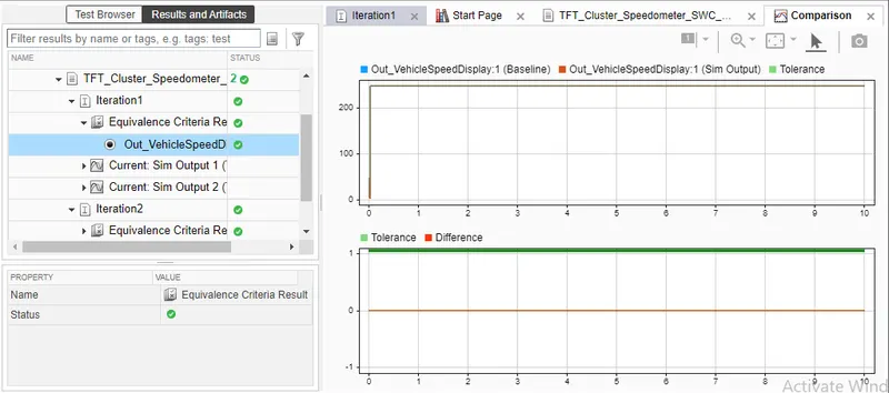
-For iteration1;
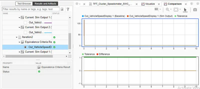
-For Iteration2;
Note: We can see results and output of others in following attached report pdf.
-Report;
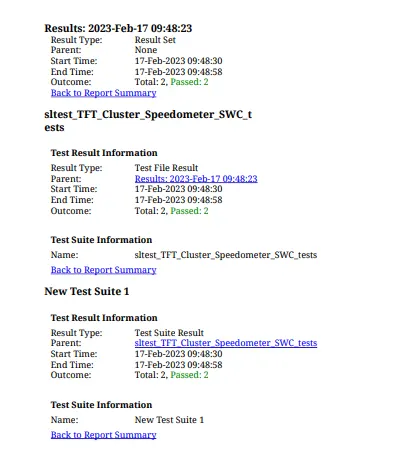
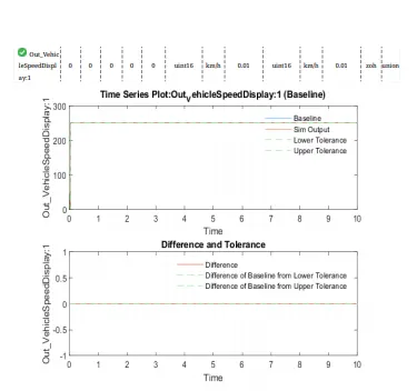
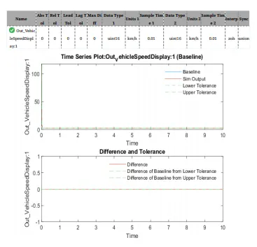
-All files and output report are attached below to see the results.
----------------------------------------------------------------------------------------
Note:MIL-SIL, Baseline Test and Back to Back test are perfomed on the model of without use of fixed Tool because of the for same tests we are not getting the proper output with the fixed Tool Model So, we have using the without used fixed tool model for geeting the proper output for the same test