Project - Speed Control of a Direct Current (DC) motor
Aim:To Simulink model for the DC motor will be developed per the schematic shown in Figure 1. and Use the Proportional, Integral, and Derivative (PID) control design knowledge gained in the training to design, develop and test a controller to maintain a desired speed for the motor.
Explanation:
DC motor
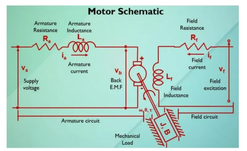
Fig.1 Schematic diagram of dc motor.
The DC Motor is the one that takes input supply voltage i.e direct current and gives the output at shaft in the form of speed(w) to spin the load connected to it.
The dc motor has armature circuit it contains Armature resistance(Ra), Armature inductnance(La) and armature circuit takes the current(Ia);And the feild circuit contains field resistance(Rf) and field inductance(Lf) when field circuit supplid by supply voltage of Vf the field circuit takes the current (If).
Here we will consider only armature circuit, the rotor and shaft assumed to be rigid. we will further assume a viscous friction model, that is, the friction torque is proportional to the shaft anguler velocity.
Mathematical modeling from the first principle and modeling an electrical engineering system
System equation:
The torque T generated by the DC Motor is proportional to the torque constant and armature current.
T=Kt*Ia.----------where, Ia is armature current.
The Back EMF Vb is directly proportional to the Back emf constant and angular velocity.
Vb=Km*w.----------where,w is the anular velocity.
We will take Ke=Kt because of it SI units is same, and WIll assume as K.
By using newton's 2nd law and kirchhoff's voltage law we can have two governing equation for dc motor is as below,
J*theta_dot+B*theta_dot=K*Ia--------------------------------------[1]
La*dIa/dt+R*Ia=Vs-K*theta_dot-------------------------------------[2]
Where, theta_dot is angular velocity.
Transfer function
By applying the laplace transform, the above equation becomes and can be expressed in laplace variable s,
s(J.s+B)*theta(s)=K*Ia(s)--------------------------------------------------[3]
(La*s+Ra)*Ia(s)=Vs(s)-K.s*theta(s)---------------------------------------[4]
Then the final opem loop transfer equation by eliminating the Ia(s) and cosidering the output as rotational speed and inpt as a Supply voltage Vs,
theta_dot(s)/Vs(s)=K/[(J.s+B)(La.s+R)+K^2]--------------------------[5]
Note, theta_dot=w, is the angular velocity.
PID Controller
Equation for PID controller is,
PID controller=Kp+(Ki/s)+Kd.s------------------------[6]
Where,
Kp is the proprtional feedback gain controller .
Ki is the integral feedback gain controller.
Kd is the derivative feedback gain controller.
Simulink based modeling
Simulink Model For given model of DC Motor
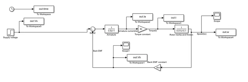
Fig.2 Simulink model for Dc motor
We will create matlab script for designing the parameter shown as below,
J=0.01; %Moment of inertia of the motor in kgm^2.
B=0.1; %Motor viscus friction constant in N-m-s.
Km=0.01; %Back EMF constant in V//rad/s.
Kt=0.01; %Motor torue constant in N-m/Amp.
Ra=1; %Armature resistance in Ohm.
La=0.5; %Armature inductance in Henry.
Clock
The clock block is used to provide time of simulation for simulink model.
To workspace
The workspace black is used to store the output values in array format.
we uses the 6 wprkspace block for storing the output as time, Supply voltage(Vs), Armature current(Ia), Angular speed(w=theta-dot) and Back EMF(Vb).
Step
The step block are used to provide input to the model as a supply voltage(Vs) and final value is selected to 10 Volts and all other parameter being remains zero.
Sum
Here sum block are used for subtraction and they are posioned in the model (fig.2)
Gain
In the model we are using two gain block to store the value for multiplication and carrying the values of torque constant 'Kt' and Back EMf constant 'Kb'.
Transfer function
Here two transfer function are used one to solve the transfer form equation of armaure circuit and another to solve the transfer form equation of rotor inertia and friction as shown in model.
Scope
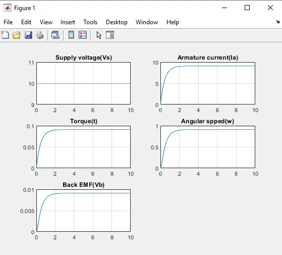
Output of fi.2
Simulink model for DC Motor with PID controller:
We are creating the model for combination of equation [5] and [6] and forming the closed loop via feedback to create error signal.
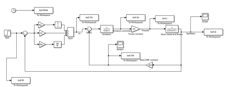
Fig.3 Simulink model of DC Motor speed control with controller.
Clock
The clock block is used to provide time of simulation for simulink model.
To workspace
The workspace black is used to store the output values in array format.
we uses the 7 wprkspace block for storing the output as time, Reference speed(N), Supply voltage(Vs), Armature current(Ia), Angular speed(w=theta-dot) and Back EMF(Vb).
Step
The step block are used to provide input to the model as a Reference speed (Nref) i.e final value is selected to 10 and all other parameter being remains zero.
Sum
Here three sum block are used for subtraction and addition for which they are posioned in the model.
Gain
In the model we are using five gain block to store the value for multiplication and carrying the values of Kp, Ki, Kd, torque constant 'Kt' and Back EMf constant 'Kb'.
Integrator
The integrator block is used to for integral control Ki at initial condition is zero.
Derivative
Basically derivative block for derivative control gain Kd.
Transfer function
Here two transfer function are used one to solve the transfer form equation of armaure circuit and another to solve the transfer form equation of rotor inertia and friction as shown in model.
Scope
The scope is used to represent the output of angular velocity 'w' in graphical representation.
Control law design and test
We wiil create matlab script for design parameter as given below,
%Design parameter for Modeling of Dc motor are follows;
J=0.01; %Moment of inertia of the motor in kgm^2.
B=0.1; %Motor viscus friction constant in N-m-s.
Km=0.01; %Back EMF constant in V//rad/s.
Kt=0.01; %Motor torue constant in N-m/Amp.
Ra=1; %Armature resistance in Ohm.
La=0.5; %Armature inductance in Henry.
fn=1; %is the natural frequency in hz.
wn=6.2832; %sqrt(k/m)is the natural frequency in rad/sec.
zeta=0.5; % Damping ratio for underdamped syetem design.
%Using state space model for dc motor in matrix form is below,
A=[-(B/J) (Kt/J);-(Km/La) -(Ra/La)];
b=[0;1/La];
%Desired poles are bellow
p1=-zeta*wn+wn*sqrt(zeta^2-1);
p2=-zeta*wn-wn*sqrt(zeta^2-1);
P=[p1;p2];
K=place(A,b,P)
%Values for Kp, kd and Ki using pole placement technique are below,
Kp=38.3133;
Kd=-2.8584;
Ki=0;
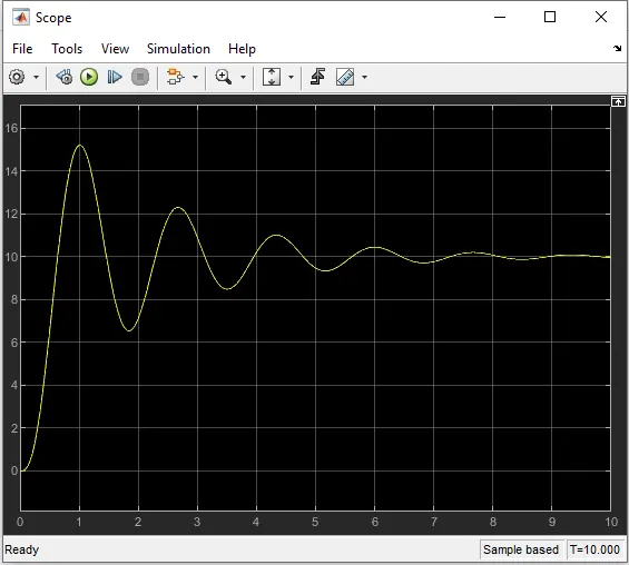
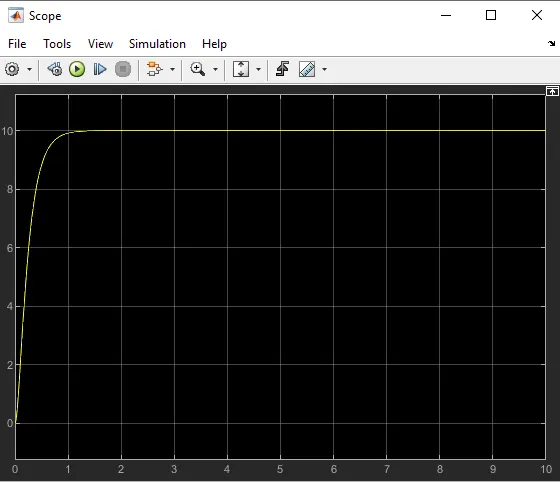
%Following values are Selected to get output as per setting time<2s, Overshoot<5% and
%Steady stae error<1%
Kp=38;
Kd=4;
Ki=36;
Output for fig.3
Output for angular speed(w) at initial Kp=38.3133, Kd=-2.8584 and Ki=0;(via scope)
Output for angular speed(w) at improved Kp=38, Kd=4, and Ki=36;(via scope)
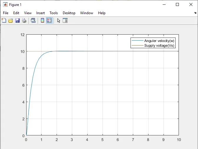
Output for supply voltage 'Vs' and angular velocity 'w' at improved Kp=38, Kd=4, and Ki=36; via matlab plot command
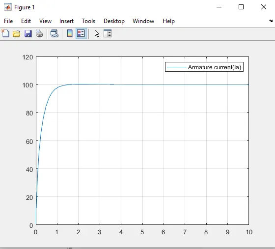
Output for Armature current 'Ia' at improved Kp=38, Kd=4, and Ki=36; via matlab plot command
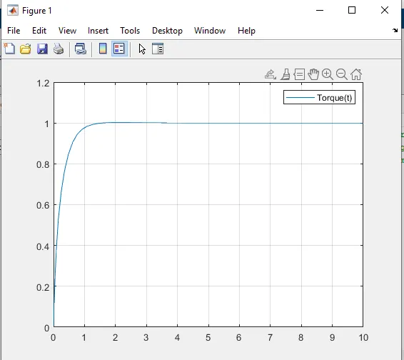
Output for Torque 't' at improved Kp=38, Kd=4, and Ki=36; via matlab plot command
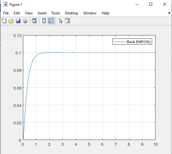
Output for Back EMF 'Vb' at improved Kp=38, Kd=4, and Ki=36; via matlab plot command
Stability of a Dynamic system
For this we will change the Reference speed Nref=20 with keeping Kp=38; Kd=4; Ki=36; remains same.
Output at Nref=20
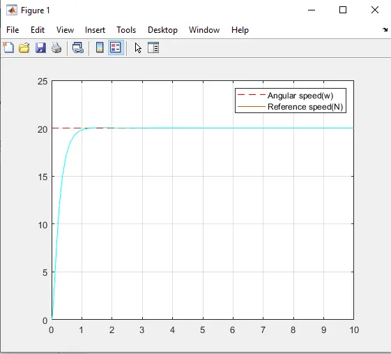
We can see that output characteristics for Nref=10 and Nref=20......etc are same & we have regulated speed at any desired speed.
Conclusion:
By using a PID controller we can regulate the speed of the DC Motor with appropriate selection of values for the P, I and D we get the output for control design objective i.e settling time<2s, overshoot<5%, and steady-state error<1% and can get the stability at any desired speed.