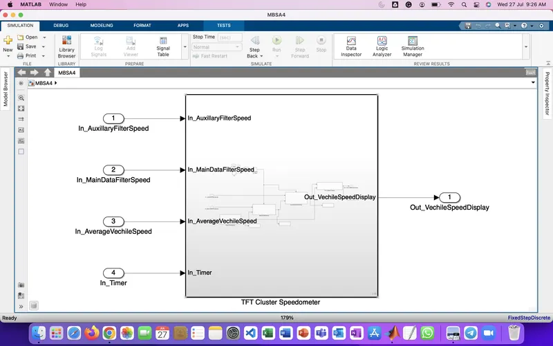
Project 2 - Development of TFT Cluster Speedometer Software Component
Develop the Simulink model based on the given requirements and also create SLDD file and link the same to the model.
Perform the complete V and V workflow for the obtained model
Development of TFT Cluster Speedometer Software Component
Cluster Instrument receives the signals from other ECU via CAN bus interface. It also receives commands from the driver via steering wheel buttons. The signals are then processed by the Cluster ECU, after which the Cluster ECU may send the vehicle information to the LCD or light the LEDs and so forth, according to the results. Therefore, the Cluster ECU can be viewed as a carrier of the information flow.
Requirements:
1.1 Calculating TFT Display Speed
|
Average Vehicle Speed would be displayed only if its between 2 kmph & 250 kmph. Any value outside this range will be discarded by its lower limit & upper limit |
|
When Average Vehicle Speed is < 2 kmph, DisplaySpeed = 2 kmph |
|
When Average Vehicle Speed is in between 2 kmph & 250 kmph, DisplaySpeed = Average Vehicle Speed |
|
When Average Vehicle Speed is > 250 kmph, DisplaySpeed = 250 kmph |
1.2 Main Data Filtering
|
Main Data Filtering subsystem will be activated for every 10th millisecond |
||||||
|
DisplaySpeed1 (t) = ((DisplaySpeed (t) x 0.65)/ Main Filter Speed Value) 0.05 |
1.3 Auxiliary Data Filtering
|
Auxiliary Data Filtering subsystem will be activated for every 10th millisecond |
|||||||
|
DisplaySpeed_Filter (t) = ((DisplaySpeed1 (t) x 0.78)/ Auxillary Filter Speed Value) - 0.03 |
1.4 TFT Speed Output
|
If |(DisplaySpeedFilter - DisplaySpeed)| > 1.5 |
|
{ |
|
Vehicle Speed Display = DisplaySpeed |
|
} |
|
else |
|
{ |
|
Vehicle Speed Display = DisplaySpeed Filter |
|
} |
Sol: