Project 2_Design & Analysis of a Hostel building at Guwahati, Assam
Question. The architectural drawings of a G+3 RCC building is provided. The following information on the building is to be used:
- Location – Guwahati, Assam
- Function – Hostel block in an academic institute
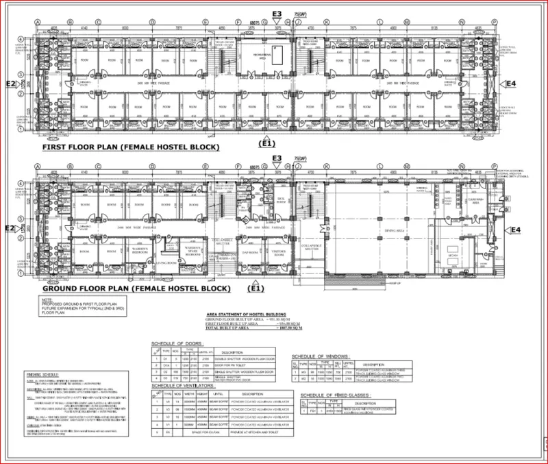
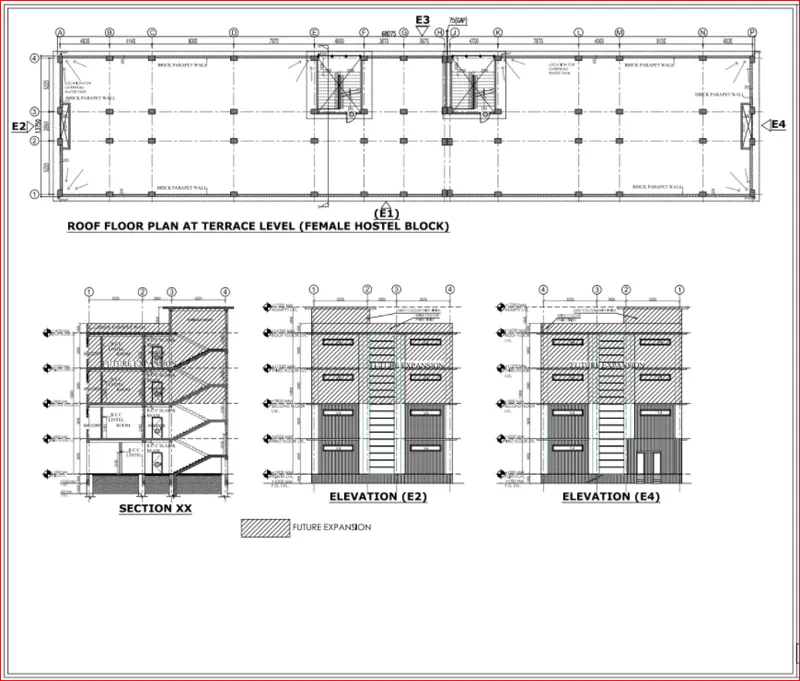
The walls will be made of AAC blocks. Other loadings are to be calculated as per the architectural drawings.
The buildings rests on type 3 soil. Piles of length 10 meters and 500 mm diameter with a load-carrying capacity of 280 KN is to be used.
The ground floor level will be at a height of 2 meters above the existing site level to avoid floodwater enter the building.
M25 grade of concrete with Fe500 for longitudinal reinforcement and Fe 415 for shear reinforcement is to be used.
The following design IS codes will be required for reference:
- IS 875 part 1
- IS 875 part 2
- IS 13920
- IS 1893
- IS 2911 part 2
- IS 456
- SP 34
Students will have to produce the following:
- Etabs model for the two blocks on either side of the expansion gap.
- Foundation details illustrating the pile & pile cap reinforcement.
- Tie beam details connecting the pile caps.
- Column reinforcement.
- Framing plan for typical floor.
- Beam reinforcements for ground floor.
AIM: To analyse and design the hostel building located in Guwahati,Assam.
Here we will be using three different softwares in order to design and analyse the hostel building, and these three softwares are:
-ETABS: We will be using ETABS software in order to model,analyse and designing the superstructure of the hostel building.
-SAFE: And we will be using the SAFE software in order to model,analyse and design the foundation of the building.
-AutoCAD: And we will be going to use AutoCAD software for the reinforcement detailing and creating construction drawings using the AutoCAD software.
- So above software we will be going to use to design and analyse the hostel building.
PROCEDURE:
- In this project we will be going to use three different softwares ETABS,SAFE and AutoCAD. So here first we will be going to work with the ETABS software for the designing and analysing and for modelling this building's superstructure.
- So lets get started for the part 1 : ETABS modelling.
- ETABS Modelling:
- In order to design and analyse the hostel building first thing that we have to do is to open the ETABS software.
- After opening the ETABS software there will be an option called New model click on that option.
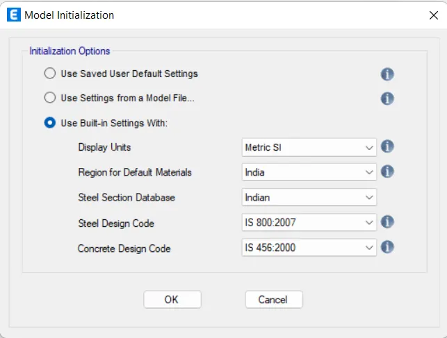
- After clicking that option there will be a dialouge box named as Model Initialization and in that dialouge box fill the necessary data regarding the codes that we are going to use to design the given hostel building just as shown in the below given image:
- New model has been opened,so after opening the model now we have to edit the story data and the grid data accordingly.
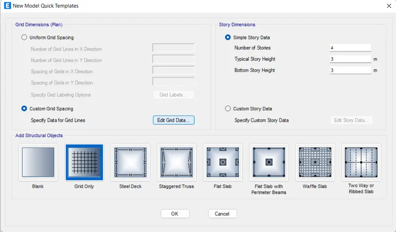
- After that there will be another dialouge box named as New Model Quick Templates,in that dialouge box there will be another option called Custom Grid Spacing check on that option after that there is another option called Edit Grid Data just as shown in the below given image:
- And now there will be another dialouge box named as the Grid System Data,in that dialouge box provide the grids in both the direction according to the give architectural plan as shown in the below given image:
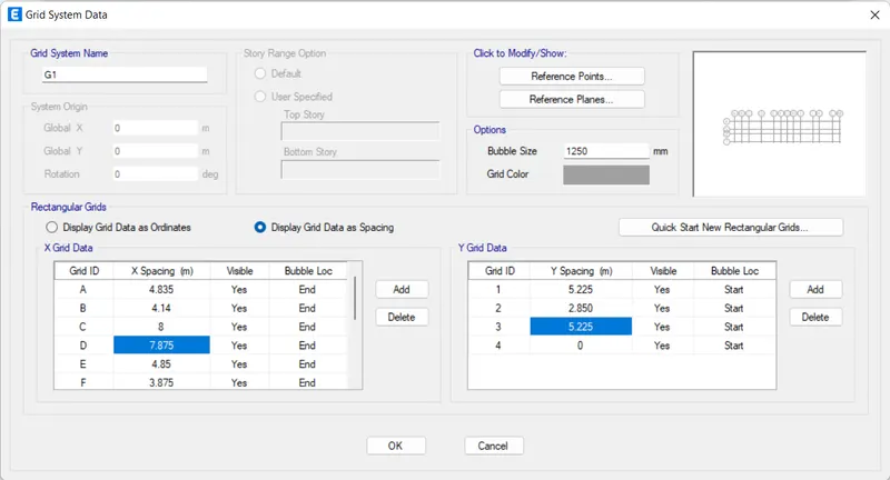
- After adding the grids now we will be adding the stories as this building is G+5 building now add the stories there is a dialouge box named as the New Model Quick Templates,in that dialouge box there will be another option called Custom Story Data check on that option after that there is another option called Edit Story Data just as shown in the below given image:
- After this there will be another dialouge box named as the Story data,in that dialouge box edit the number of stories and the stories height and other relevant data just as shown in the below given image:
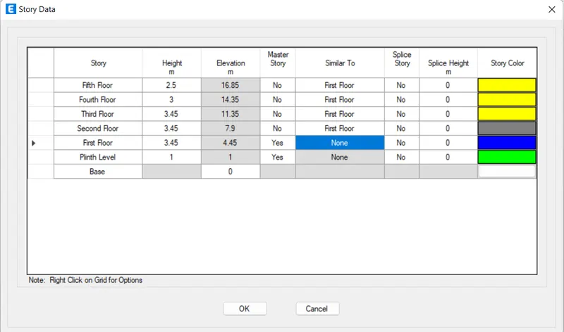
- After setting the grid system and the story data this is how it will be looking like in the plan view and the 3D view,below is the given images:
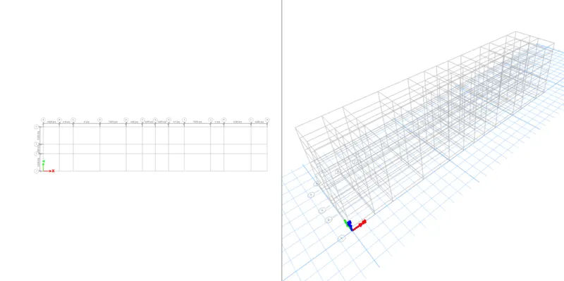
- After this now we will be defining the Materials and the Section Properties.
- So in order to assign the materials we first need to go to the Define menu then there will be another option called Material Properties click on that option just as shown in the below given image:
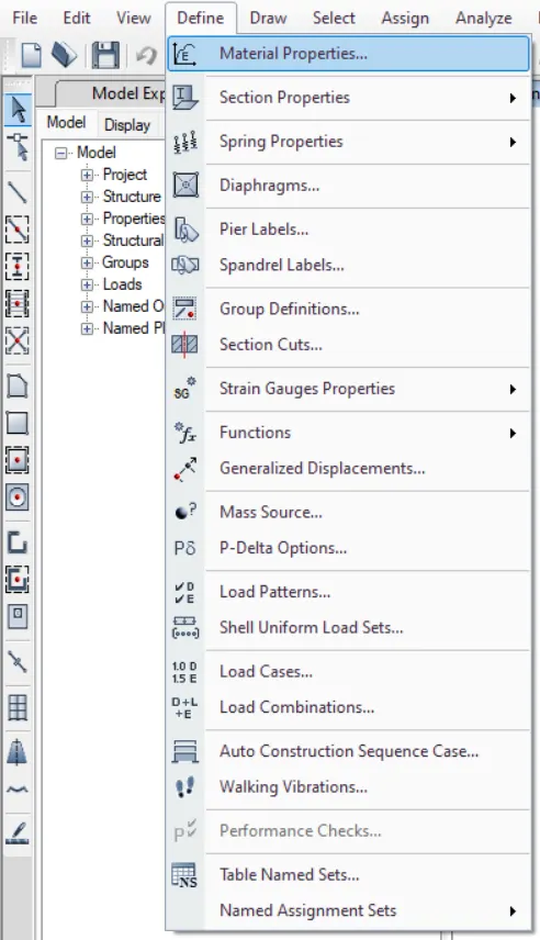
- After clicking on that option there will be a dialouge box named as the Define materials in that dialouge box there will be an option called Add new material just click on that option just as shown in the below given image:
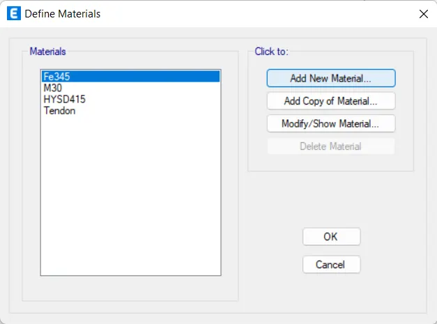
- After that there will be another dialouge box named as the Add New Material Property in that dialouge box fill the all appropriate data in that dialouge box.
Region - India.
Material Type - Concrete.
Standard - Indian.
Grade - M25.
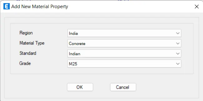
- After that there will be another dialouge box named as the Material Property Data in that dialouge box fill the appropriate data that we need in designing purpose.
- In that dialouge box name the material as M25 and all the other data just as shown in the below given image:
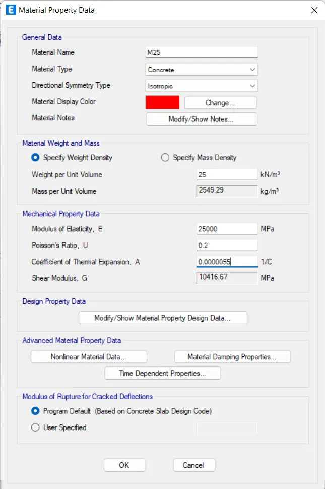
- And then click OK, M25 concrete material has been added in the material list just as shown in the below given image:
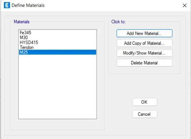
- After adding M25 now we have to add the rebar material,so i order to do that go to the Define material dialouge box click on the option Add New Material just as shown in the below given image:
- After this there will be another dialouge box named as the Add New Material Property in that dialouge box fill the all appropriate data in that dialouge box.
Region - India.
Material Type - Rebar.
Standard - Indian.
Grade - HYSD Grade 415.
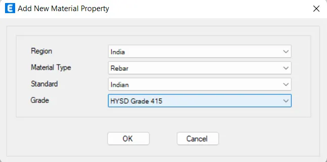
- After that there will be another dialouge box named as the Material Property Data in that dialouge box fill the appropriate data that we need in designing purpose.
- In that dialouge box name the material as HYSD Grade 415 and all the other data just as shown in the below given image:
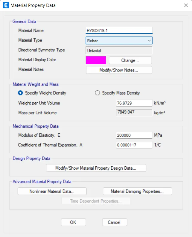
- And then click OK, Rebar HYSD Grade 415 material has been added in the material list just as shown in the below given image:
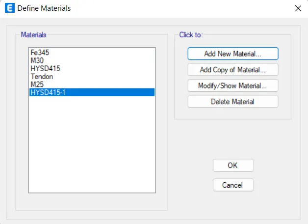
- After adding HYSD Grade 415 now we have to add the another material,so in order to do that go to the Define material dialouge box click on the option Add New Material just as shown in the below given image:
- After this there will be another dialouge box named as the Add New Material Property in that dialouge box fill the all appropriate data in that dialouge box.
Region - India.
Material Type - Rebar.
Standard - Indian.
Grade - HYSD Grade 500.
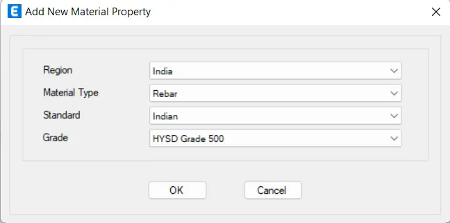
- After that there will be another dialouge box named as the Material Property Data in that dialouge box fill the appropriate data that we need in designing purpose.
- In that dialouge box name the material as HYSD Grade 500 and all the other data just as shown in the below given image:
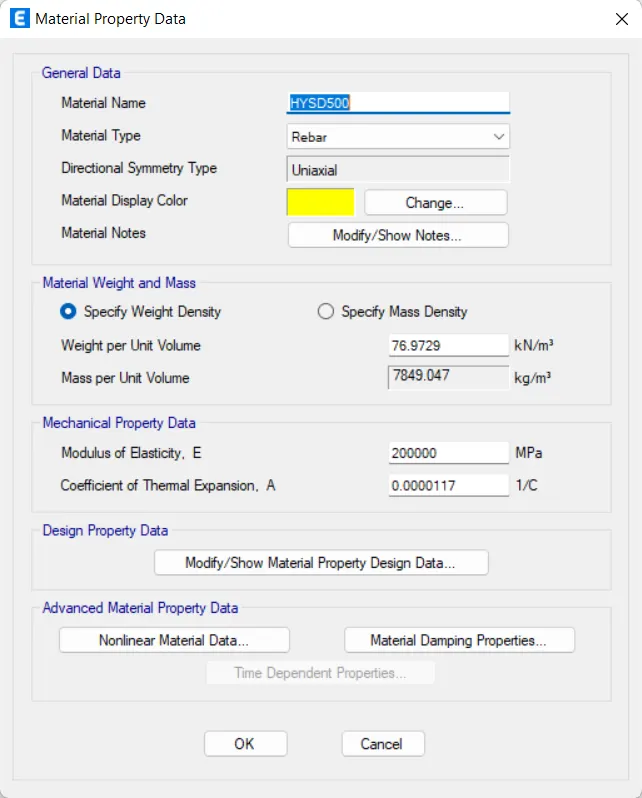
- And then click OK, Rebar HYSD Grade 500 material has been added in the material list just as shown in the below given image:
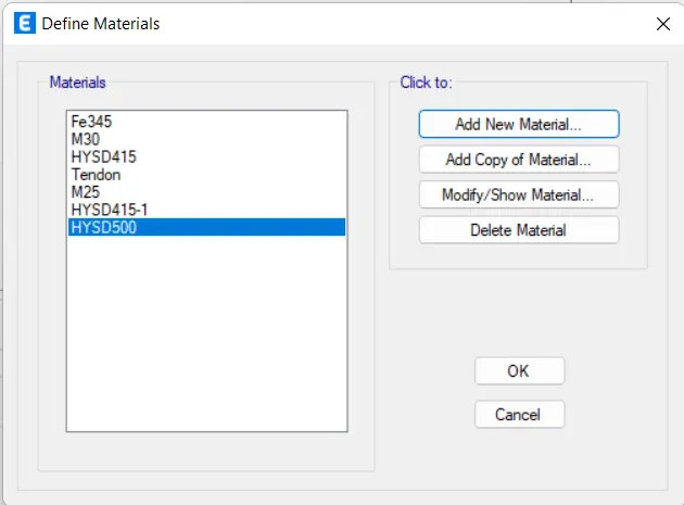
- Now that all the materials have been added in the list now we have to define the section properties.
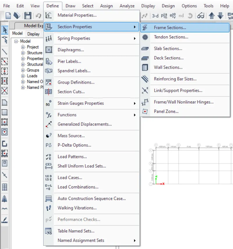
- So in order to define the section properties just go to the Define tab there will be a drop-down list and in that list there will be an option called Section properties click on that option after that there will be another drop-down list in that list there will be another option called Frame Sections just click on that option just as shown in the below given image:
- After this there will be a new dialouge box named as the Frame Properties,in that dialouge box there is an option called Add New Property just click on that option as shown in the below given image:
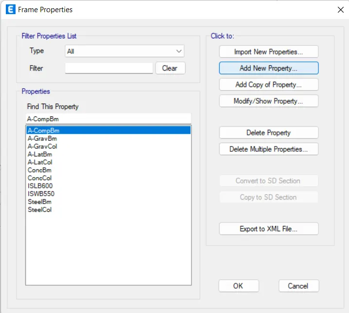
- Now we will be adding the sections properties like beam,columns etc.
- COLUMN (450 mm X 650 mm):
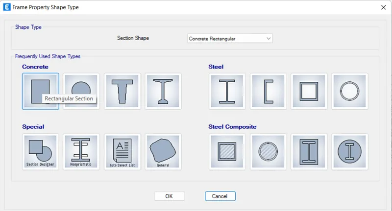
- So after clicking on the option Add New Property there will be another dialouge box named as the Frame Property Shape Type,in that dialouge box choose the shape of the column here I will be choosing rectangular shape and then just click OK just as shown in the below given image:
- After that there will be another dialouge box named as the Frame Section Property Data just as shown in the below given image:
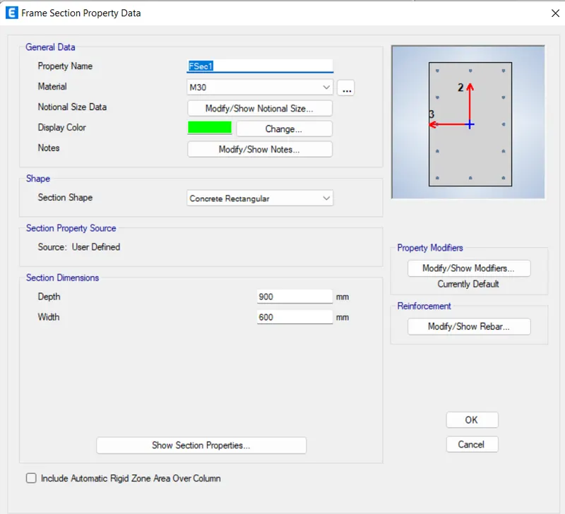
- Fill out the relevant data in this dialouge box just as shown below:
- General Data:
Property Name : Column450X650.
Material : M25.
- Section Dimension:
Depth : 650.
Width : 450.
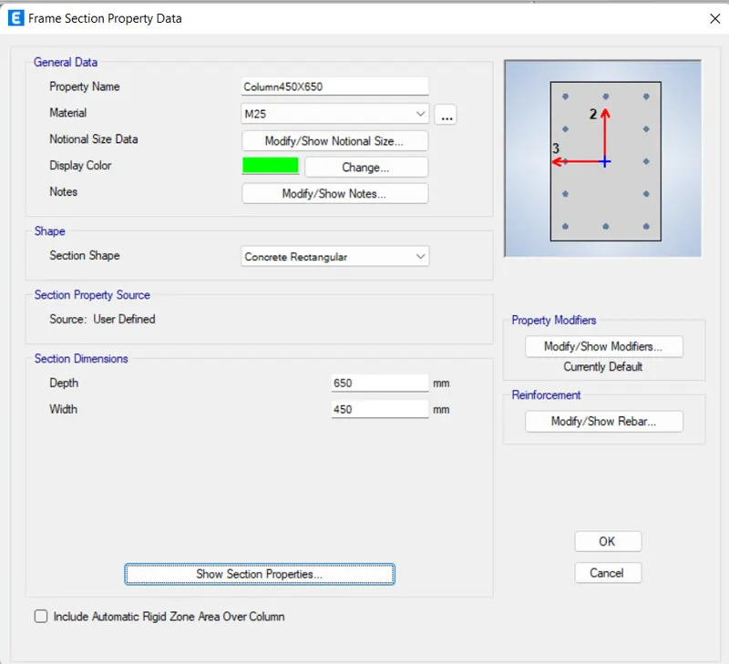
- In that dialouge box there is another option at the right-side of screen and that option is Modify/Show Rebar just click on that option then there will be another dialouge box named as Frame Section Property Reinforcement Data,in this dialouge box fill the data just as shown in the below given image:
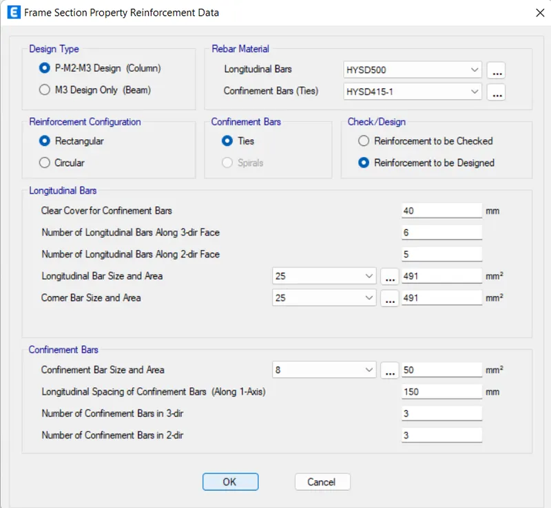
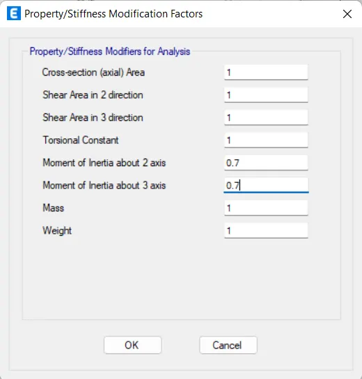
- And now again in the same dialouge box there is another option called Modify/Show Modifiers,so in that dialouge box put moment of inertia along 2 and 3 axis as 0.7% because for the column moment of inertia reduces by 0.7% according to the IS code just as shown in the below given image:
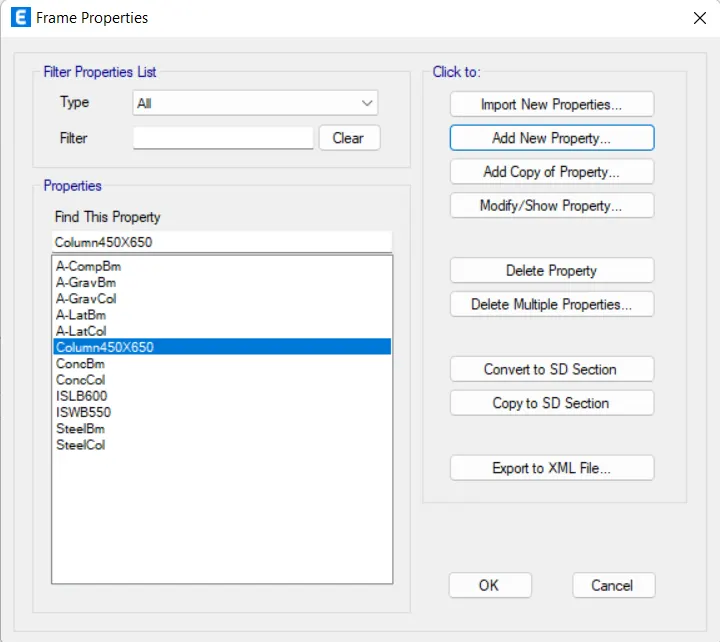
- The column have been added in the list as ahown in the below given image:
- BEAM 250mm X 300 mm:
- So in order to add the beam into the list then go to the Frame Properties,in that dialouge box there is an option called Add New Property just click on that option as shown in the below given image:
- Now we will be adding the sections properties for the beam 250 mm X 300 mm.
- So after clicking on the option Add New Property there will be another dialouge box named as the Frame Property Shape Type,in that dialouge box choose the shape of the column here I will be choosing rectangular shape and then just click OK just as shown in the below given image:
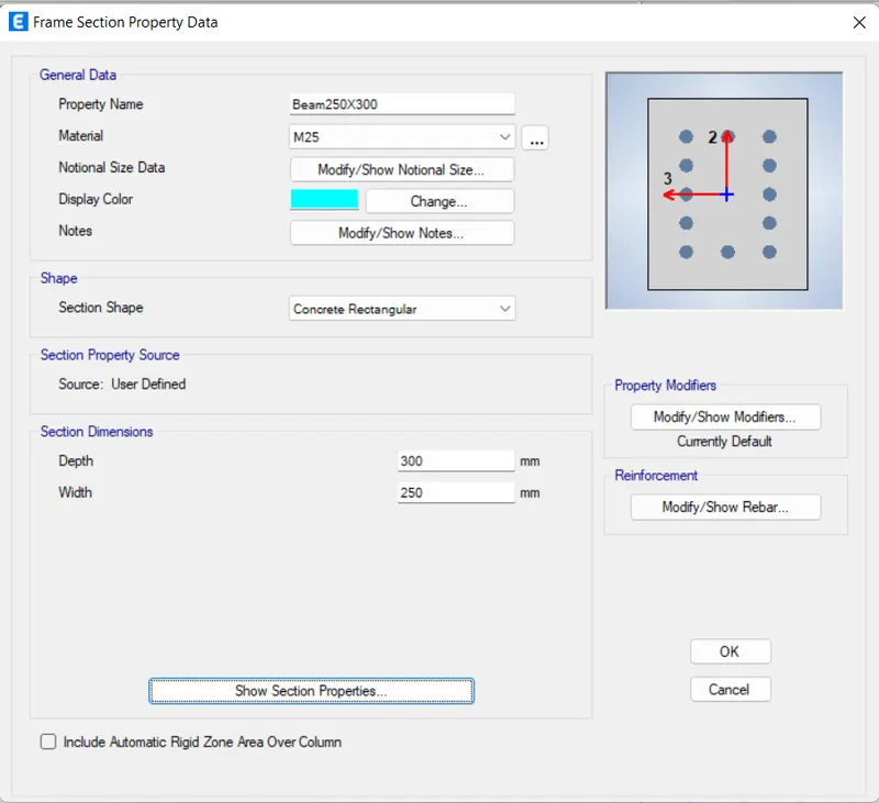
- After that there will be another dialouge box named as the Frame Section Property Data just as shown in the below given image:
- Fill out the relevant data in this dialouge box just as shown below:
- General Data:
Property Name : Beam250X300.
Material : M25.
- Section Dimension:
Depth : 300.
Width : 250.
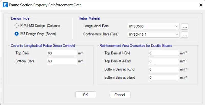
- In that dialouge box there is another option at the right-side of screen and that option is Modify/Show Rebar just click on that option then there will be another dialouge box named as Frame Section Property Reinforcement Data,in this dialouge box fill the data just as shown in the below given image:
- And now again in the same dialouge box there is another option called Modify/Show Modifiers,so in that dialouge box the moment of inertial along 2 and 3 axis as 0.35% because in the beams the moment of inertia reduces to 0.35% according to the IS code just as shown in the below given image:
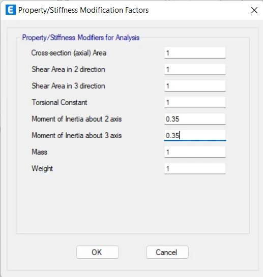
- The beams have been added in the list as ahown in the below given image:
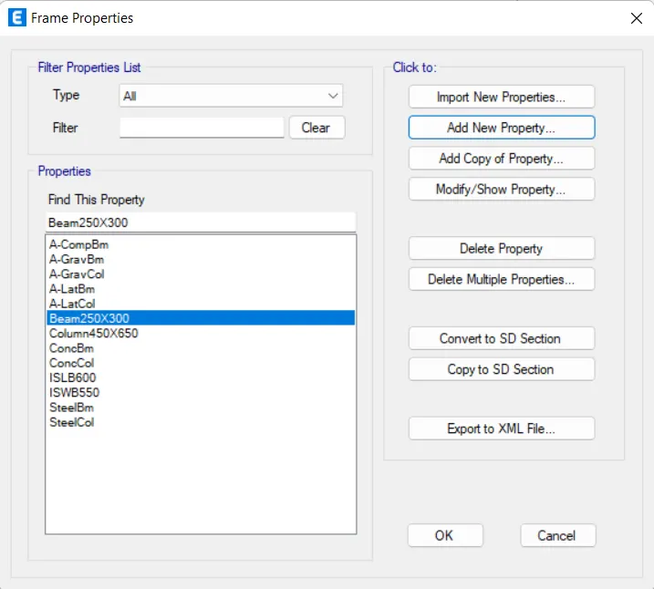
- Now that the column and beam of their respective sizes have been added to the list now we will be adding the slab property into the model.
- SLAB 150 mm Thick:
- And now we will be adding the slab, and to add the slab first do to the Define menu then there will be a drop-down list in that list there will be an option called Section Properties and then there will be another drop-down list in that list there will be another option called Slab Properties just click that option just as shown in the below given image:
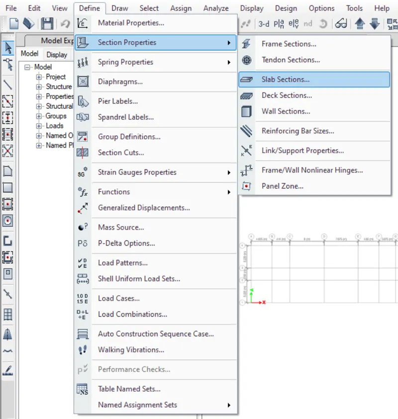
- After this there will be another dialouge box named as the Slab Properties,in that dialouge box there is an option called Add New Property just as shown in the below given image:
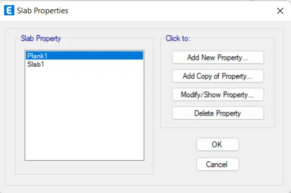
- After this there will be another dialouge box named as Slab Property Data,fill the relevant data in the given dialouge box:
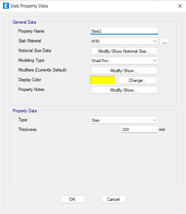
- Fill the data just as given below :
- General Data:
Property Name : Slab150.
Slab Material : M25.
Modelling Type : Membrane.
- Property Data :
Type : Slab.
Thickness : 150mm.
Just as shown in the below given image:
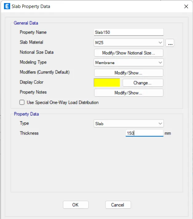
- And for the staircase we will be providing slab of 175mm thickness,and to add the slab for the staircase we will have to add the new property and then fill out the all relevant data in the new slab property dialouge box just as shown in the below given image:
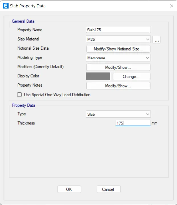
- Now that the slabs also have been added in the given list as shown in the below given image:
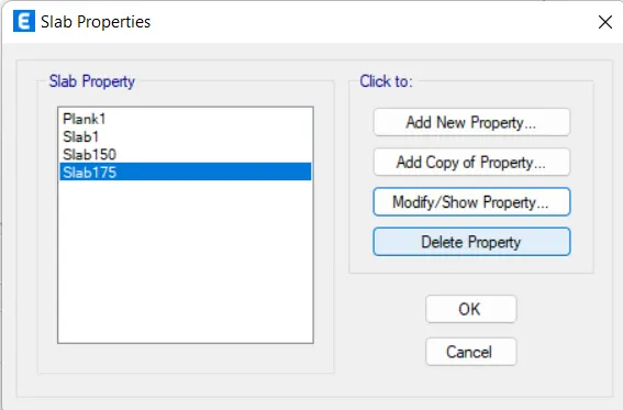
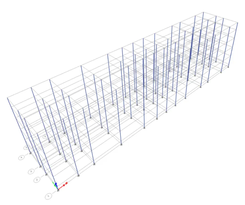
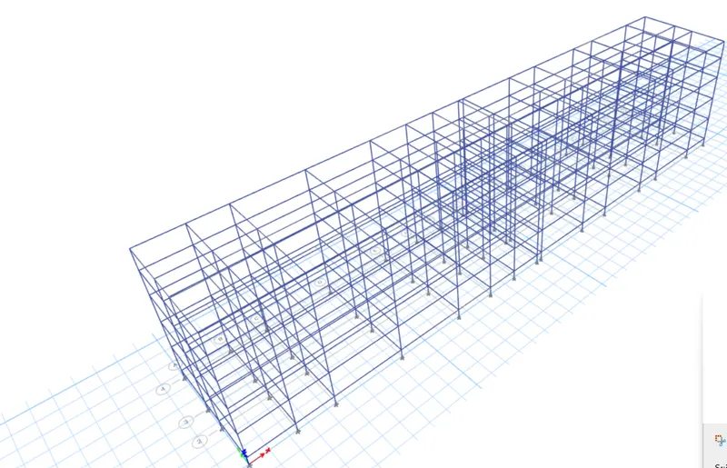
- After adding the section properties now we will be drawing slab,columns and the beams in the given plan by using quick draw tool which is provided in the software.
- COLUMNS:
In Plan View:
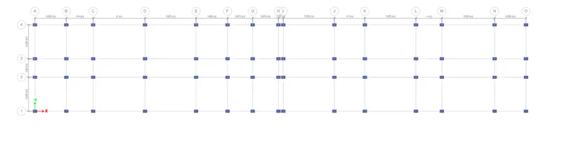
In 3D View:
- BEAMS:
In Plan View :
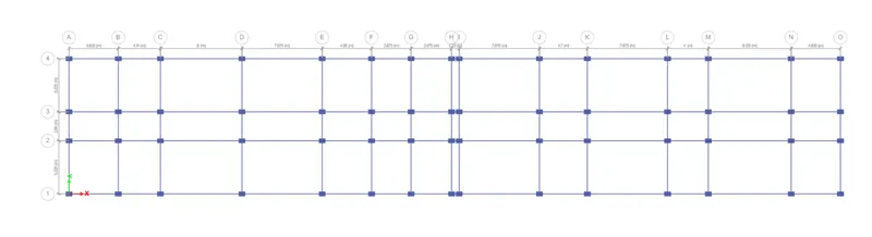
In 3D View:
- SLAB:
In Plan View:
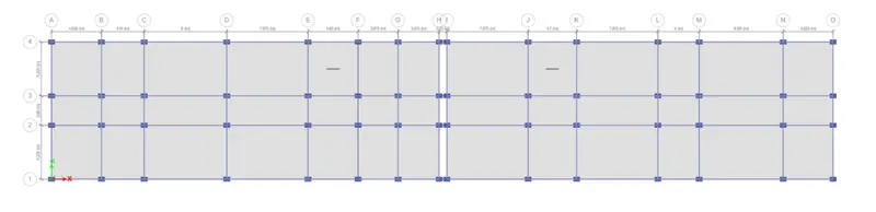
In 3D View:
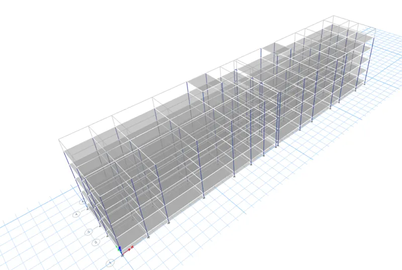
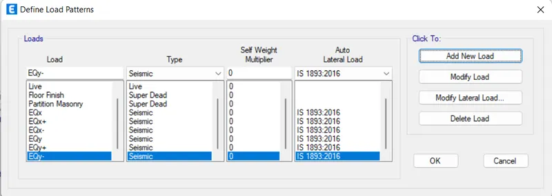
- And now we will be assigning the load patterns:
- Below are the given images of assigned loads:
- Load Patterns:
- And now we will be assigning the loads.
- LIVE LOADS:
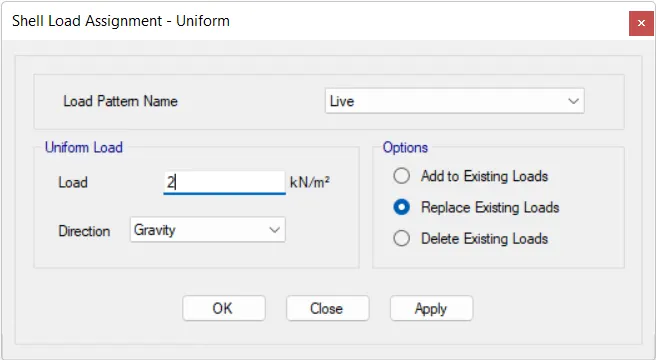
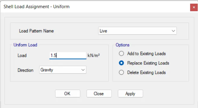
- In order to assign the loads we need to go to the Assign menubar in that there will be a drop-down list in that list there will be an option called Shell Loads and then there will be another drop-down list in that there will be another option Uniform just click on that option just as shown in the below given image:
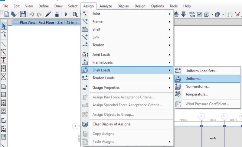
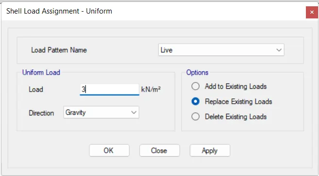
- Then there will be a new dialouge box named as the Shell Load Assignment-Uniform,in that dialouge box Fill the all relevant data.
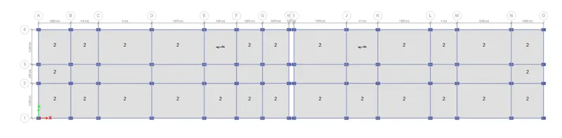
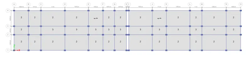
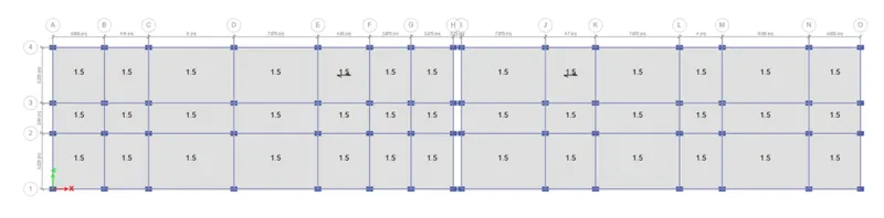
- Now seelect the floors and add the Live loads to the structure.
- Here we will be providing 2 KN/sq.m as a live load for the rooms and the dormitories of the hostel building according to the IS 875 part 2 for the residential buiding.
- As per the IS code for the hostel building:
- Living Rooms,Bedrooms and the Dormitories : 2 KnN/sq.m.
- Kitchen and Laundaries : 3 KN/sq.m.
- Public Lounges : 3 KN/sq.m.
- Store Rooms : 5 KN/sq.m.
- Dining Rooms,Cafeteria and Restaurants : 4 KN/sq.m.
- Office Rooms : 2.5 KN/sq.m.
- Bath and toilets : 2 KN/sq.m.
- Corridors, Passages and Staircase : 3 KN/sq.m.
- Balconies : 4 KN/sq.m.
- LIVE LOAD FOR CORRIDOR:
- LIVE LOAD FOR TERRACE:
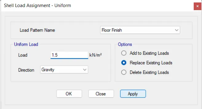
- FLOOR FINISH:
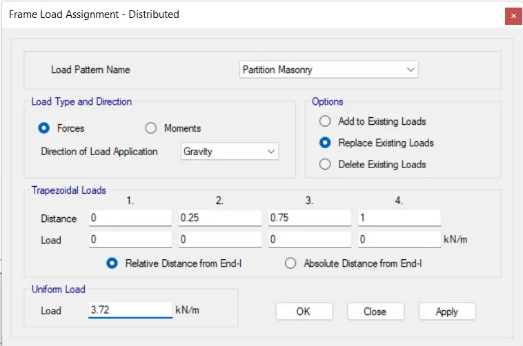
- AAC BLOCK LOADS:
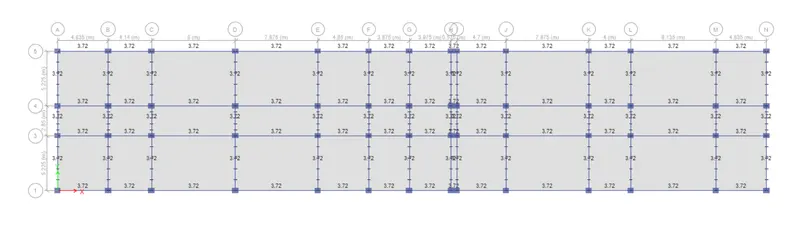
- AAC LOAD FOR TERRACE:
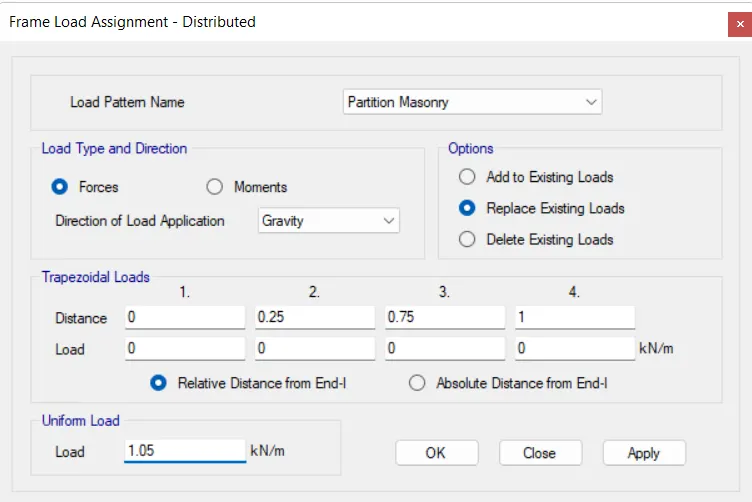
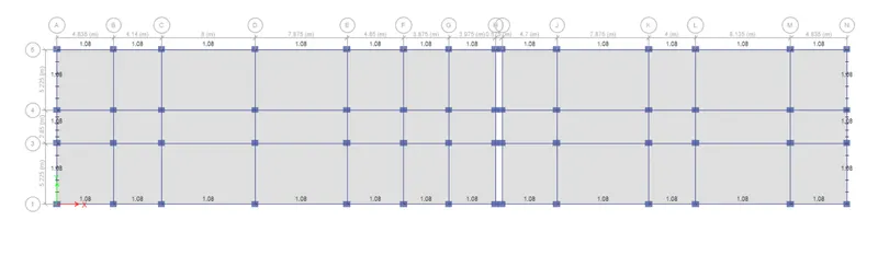
- Now we will be assigning the loads now we will be definning the Mass source,Mass Modal and the Response Sprectrum Function:
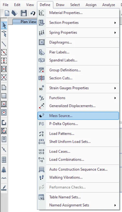
- In order to define the mass source the first thing that we need to do is that go to the Define option and there will be a drop-down list in that list there will be an option called Mass Source just click on that option just as shown in the below given image:
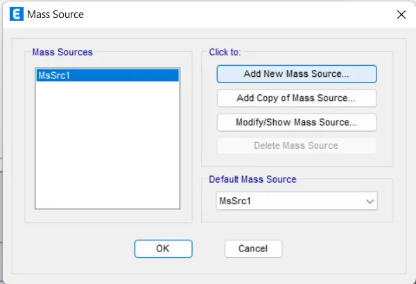
- After that there will be another dialouge box named as Mass Source and in that dialouge box there is an option called Add New Mass Source just click on that option as shown in the below given image:
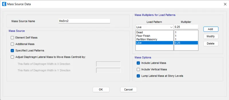
- After that there will be another dialouge box named as Mass Source Data,in that dialouge box there fill all the relevant data just as shown in the below given image:
MASS SOURCE:
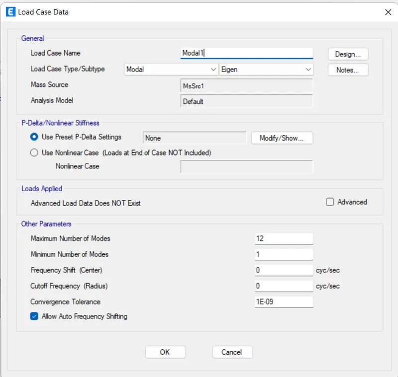
- After assigning the mass source we will be assiging the Modal case.
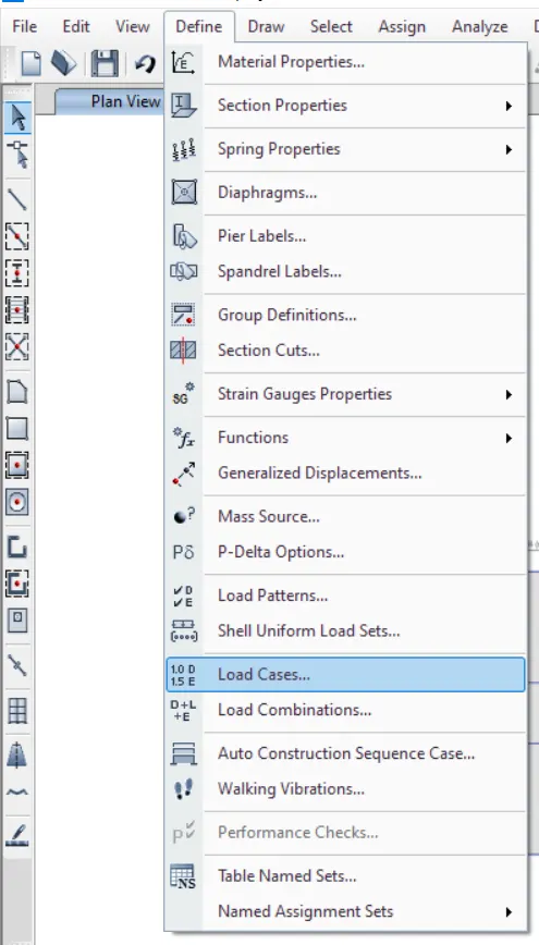
- And in order to do that first go to the Define menu then there will be drop-down list in that list there is an option called Load Cases just click on that option just as shown in the below given image:
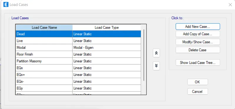
- Then there will be another dialouge box named as Load Cases in that dialolouge box there will be an option called Add New Cases just as shown in the below given image:
- Then there will be another dialouge box named as the Load Case Data,in that dialouge box fill the data just as shown in the below given image:
MODAL CASE:
- And now we will be defining the Diaphragm.
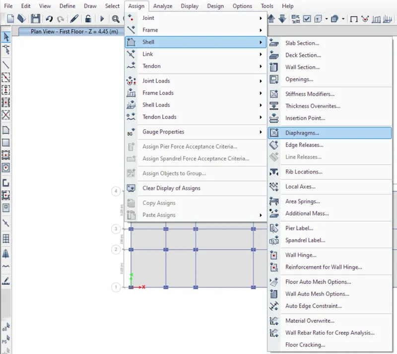
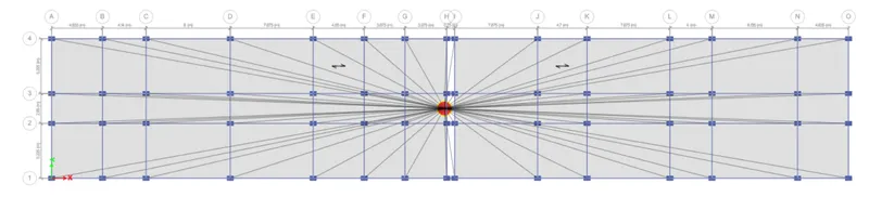
- Firstly select all the floors and then assign Diaphragm.
- So in order to assign the diaphragm,we first need to go to the option Assign then there will be a drop-down list in that list there is an option called Shell click on that option then there will be another list in that list there will be an option called Diaphragm just click on that option just as shown in the below given image:
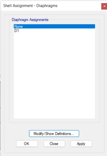
- After that there will be another dialouge box named as the Shell Assignment- Diaphragm,in that dialouge box just click the option D1 and then click on the option Apply and then click OK just as shown in the below given image:
DIAPHRAGM:
- And now we will be assigning the Response Spectrum.
- In order to assign the response spectrum just go to the option Define and then there will be a drop-down list in that list there will be an option called Function just click on that after clicking on that option there will be another list in that list there will be an option called Response Spectrum just click on that just as shown in the below given image:
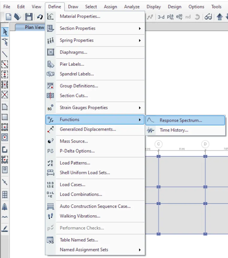
- After this there will be another dialouge box named as Define Response Spectrum Functions,in that dialouge box there will be an option called Add New Function and Choose Function Type To Add as IS 1893:2016 just as shown in the below given image:
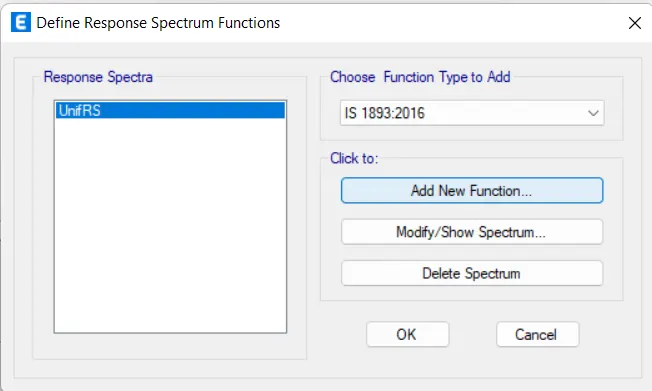
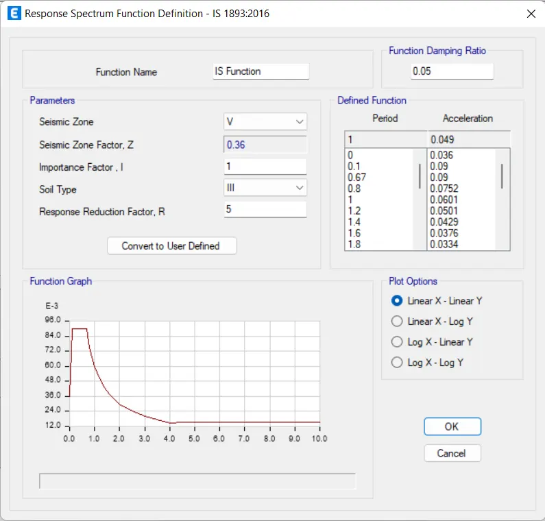
- After that there will be another dialouge box named as the Response Spectrum Function Definition- IS 1893-2016, in that dialouge box just fill the relevant data just as shown in the below given image:
RESPONSE SPECTRUM FUNCTION:
- And now we have to define the Load Cases, in order to define the load cases first go to the define option then there will be a drop-down list in that list there will be an option called Load cases just click on that option just as shown in the below given image:
- Then there will be another dialouge box named as Load Cases in that dialolouge box there will be an option called Add New Cases just as shown in the below given image:
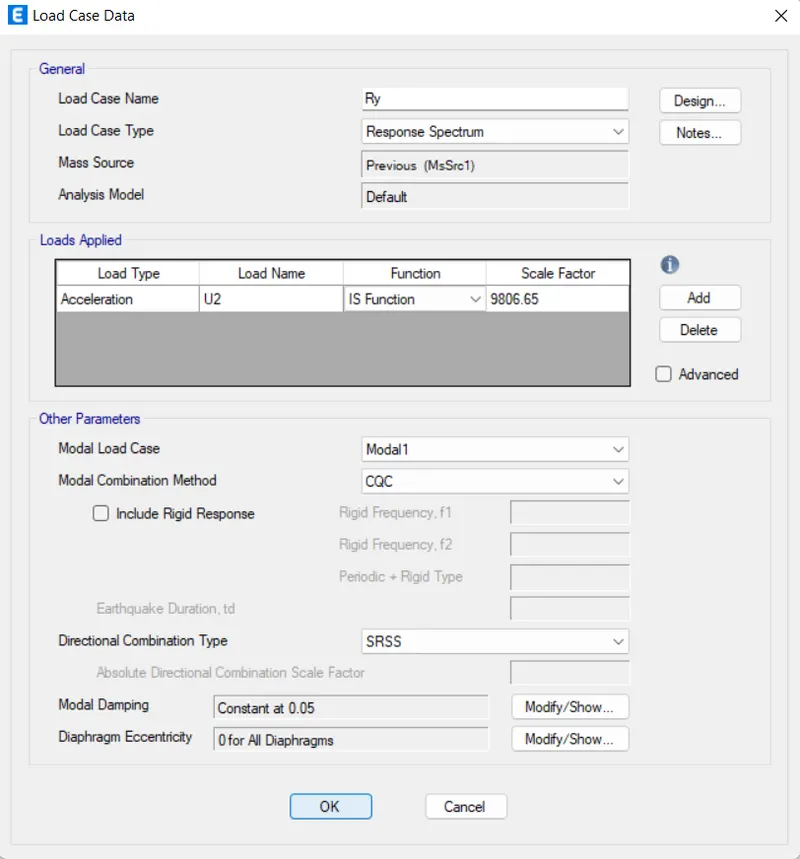
- Then there will be another dialouge box named as the Load Case Data,in that dialouge box fill the data just as shown in the below given image:
Rx:
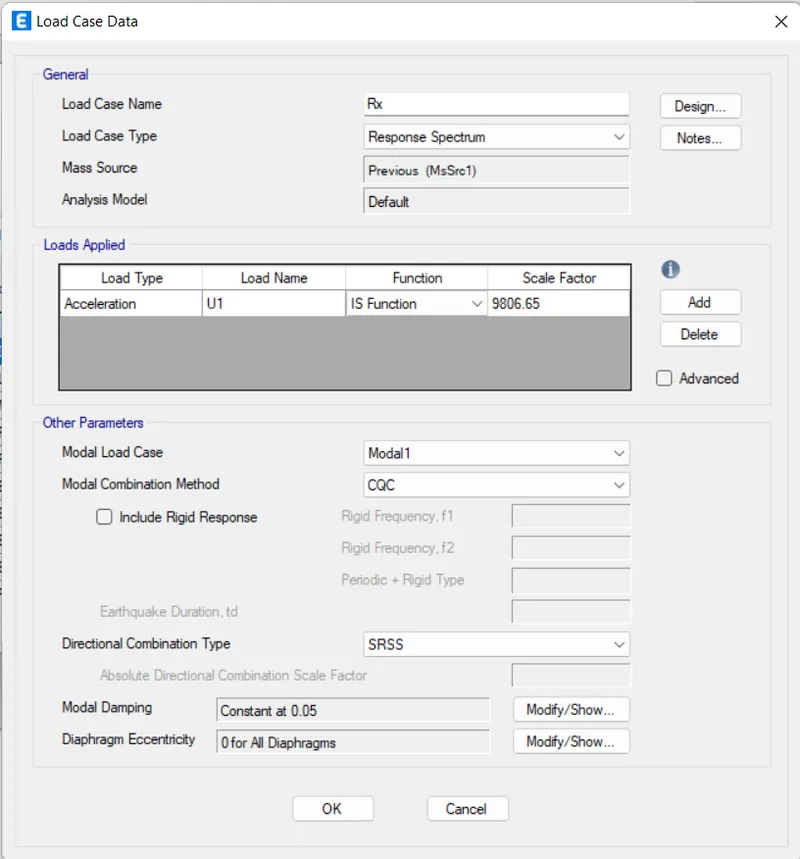
Ry:
- And now we will be defining the load combinations.
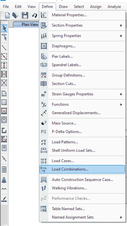
- And in order to define the load combination just go to the define tab there will be a drop-down list in that list there will be an option called Load combinations just click on that option just as shown in the below given image:
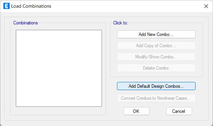
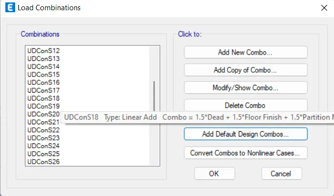
- And then there will be a new dialouge box named as Load Combinations in that dialouge box there will be an option called Add Default Design Combo just click on that option just as shown in the below given image:
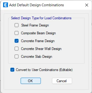
- Then there will another dialouge box named as the Add Default Design Combinations,in that dialouge box click on the option Concrete Frame design and Convert to User Combinations (Editable) just as shown in the below given image:
LOAD COMBINATIONS:
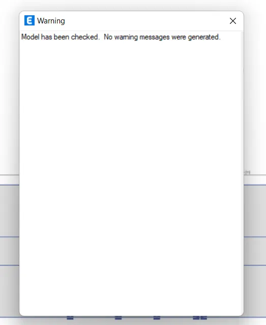
- And now we will be checking the models if there are any warnings,if there are then correct the warnings and if not and go ahead with the planning.
CHECKING THE MODEL:
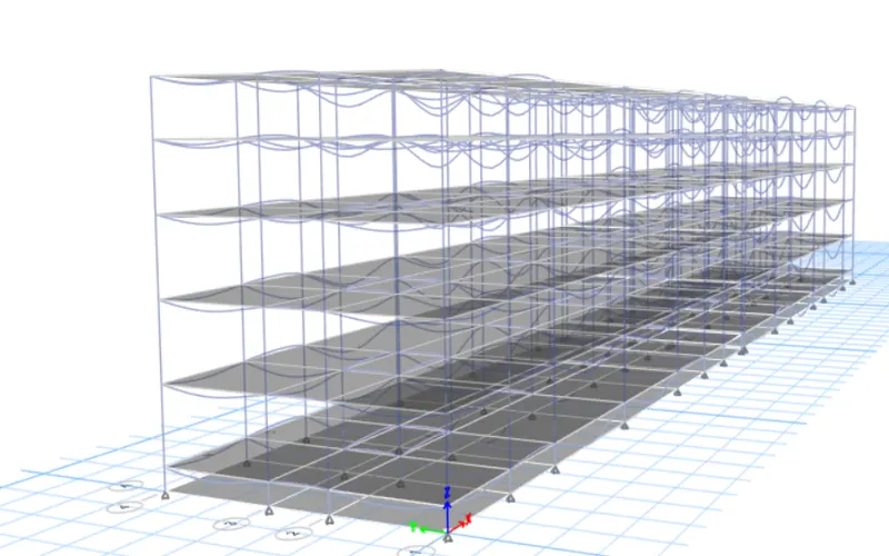
RUN ANALYSIS:
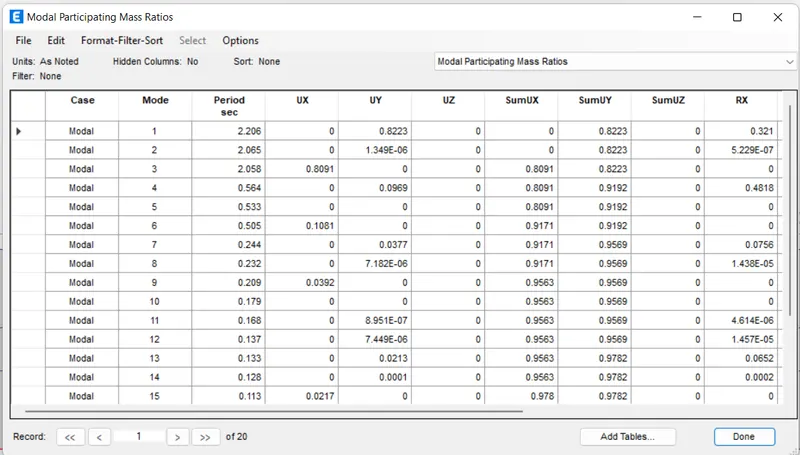
- And now we will be doing the Structural Output Check:
- MODAL RESPONSE CHECK:
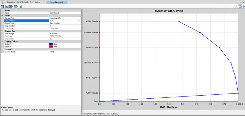
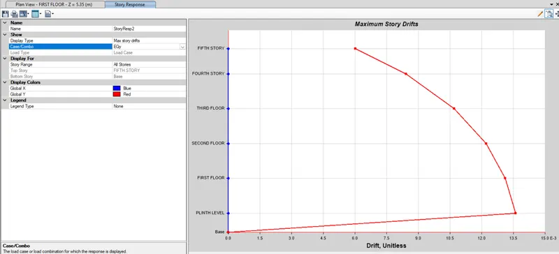
- STORY DRIFT CHECK:
EQx:
EQy:
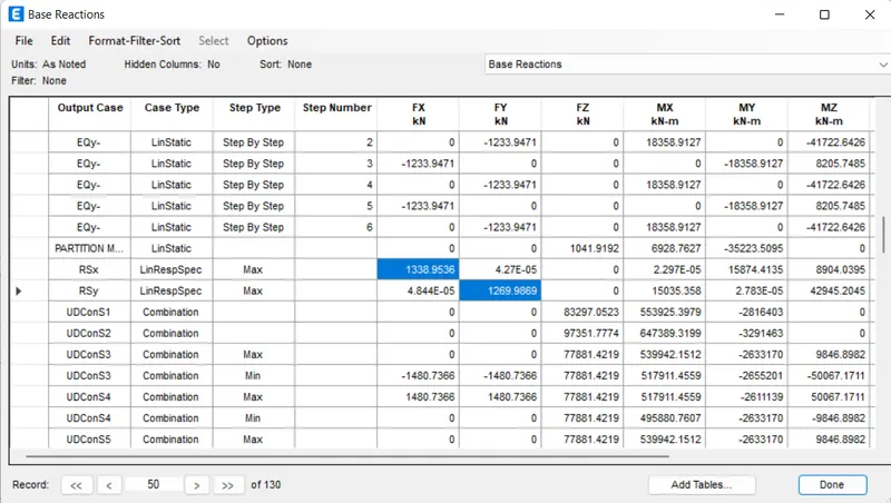
- BASE REACTIONS:
- COMPLETE DESIGN:
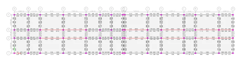
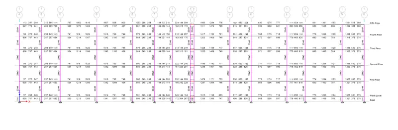
- LONGITUDINAL STEEL REQUIREMENT:
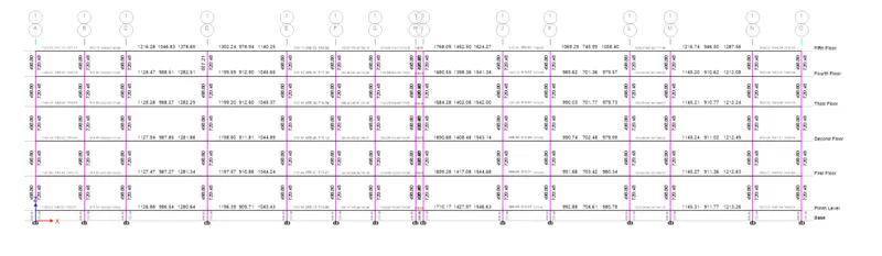
- SHEAR REQUIREMENT:
- And now we will be moving to the last part of the designing that is foundation designing using the SAFE software:
SAFE SOFTWARE:
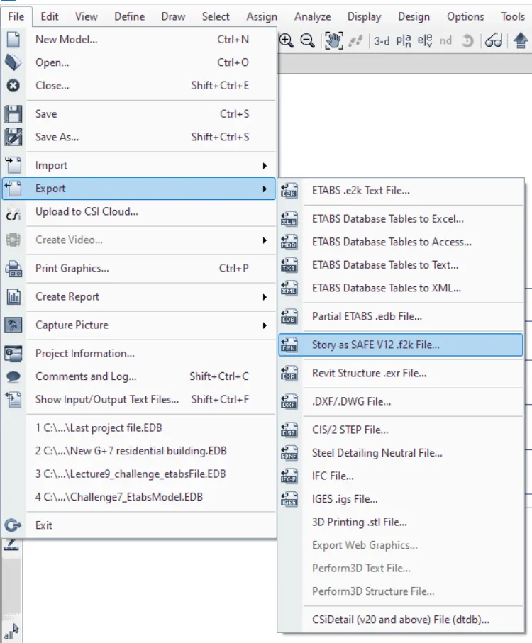
- First we need to export the file from the ETABS software.
- So in order to export the file from the ETABS software,first go to the option File then there will be an option called Export click on that then there will be another list in that list there will be another option called Story as SAFE V12.f2k File just click on that option just as shown in the below image:
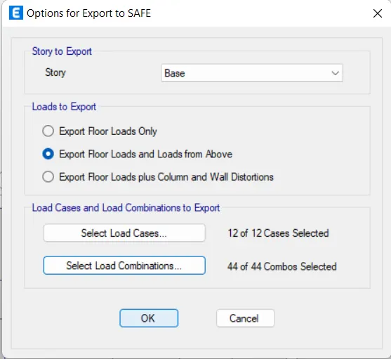
- Then there will be another dialouge box name as Options for Export to SAFE,in that dialouge box fill the details just as shown in the below given image:
- Now save the file according to our preferences and now go to the SAFE software and now open the file.
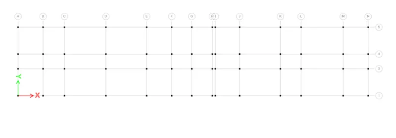
- And now first of all lets extract the given data that is already given in the question itself.
GIVEN DATA:
Column Size : 450 mm X 600mm and 600mmX450mm.
Soil Type : III.
Length of the piles : 10m.
Pile Diameter : 500 mm diameter.
Load Carrying Capacity of Pile: 280 KN.
Pile Cap - Slab type _ Matt of 50 mm thickness.
Column Cap - Slap type - Stiff of 500 mm thickness.
Pile length : 16 mm
Soil Bearing Capacity : 150 KN/sq.m.
- So the first step is to define the materials and the section property.
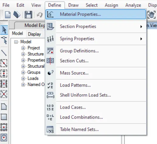
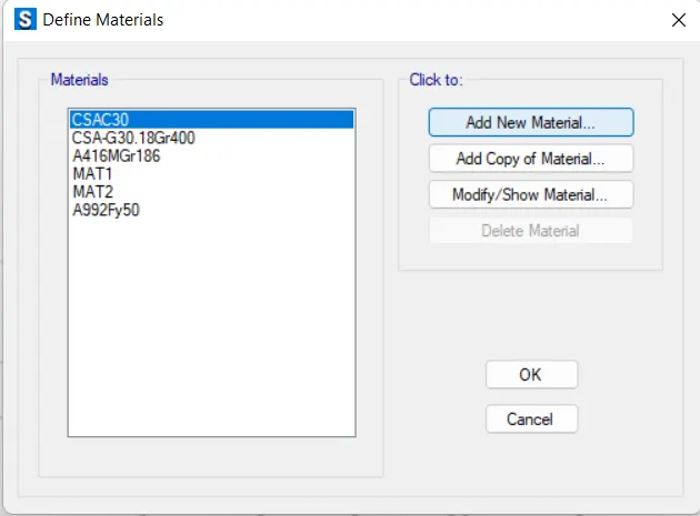
- After that there will be another dialouge box named as the Define Materials,in that dialouge box there ia an option called Add New Material just as shown in the below given image:
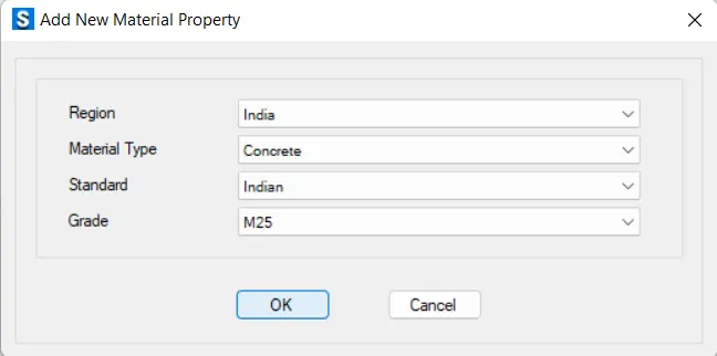
- After this there will be another dialouge box named as Add New Material Property,in that dialouge box fill the data just as shown in the below given image:
- M25:
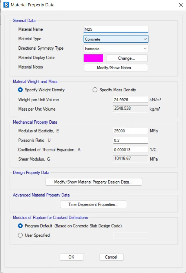
- Here the material property for concrete has been added successfully into the list.
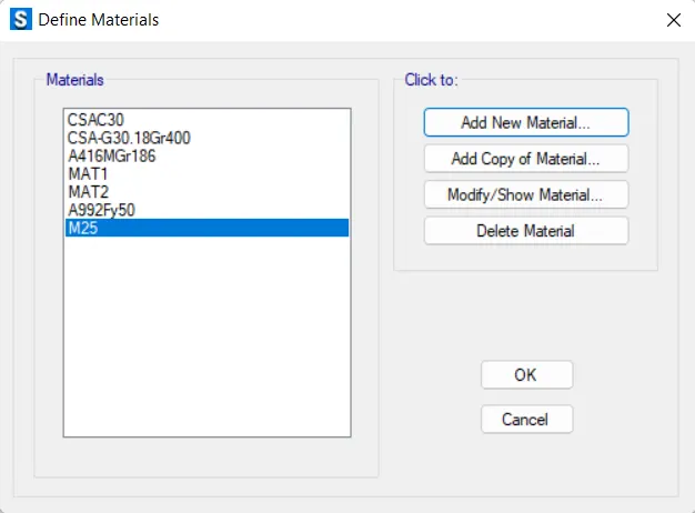
- Now we will be adding another property for the rebars.
- HYSD 500:
- Once again go to the dialouge box the Define Materials,in that dialouge box there ia an option called Add New Material just as shown in the below given image:
- After this there will be another dialouge box named as Add New Material Property,in that dialouge box fill the data just as shown in the below given image:
- HYSD 500:
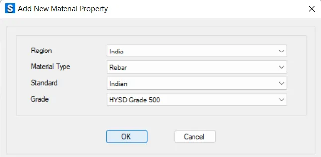
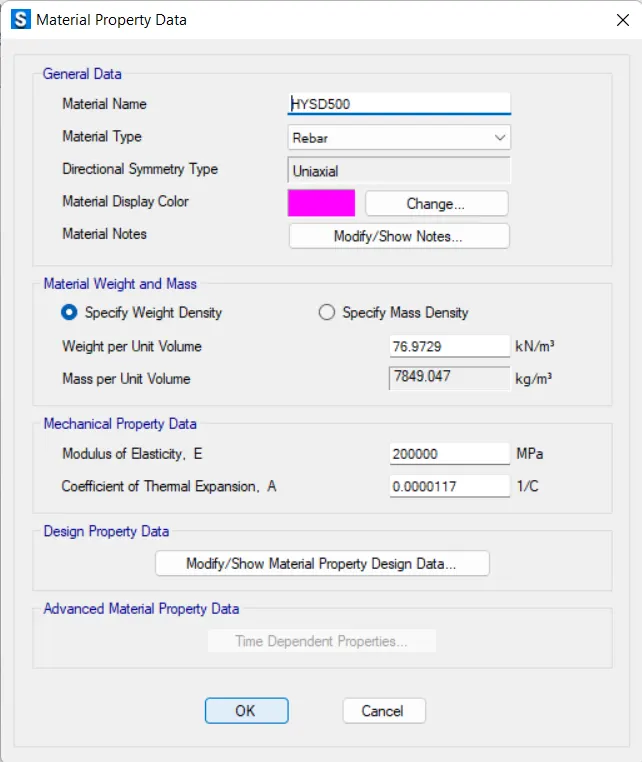
- Here the material property for rebar has been added successfully into the list.
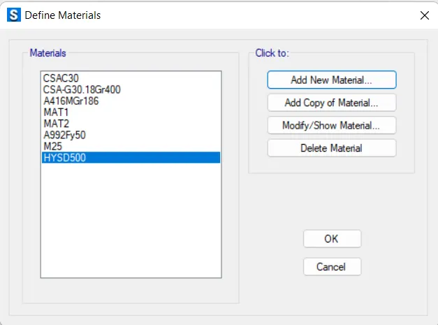
- And now we will be adding the section properties.
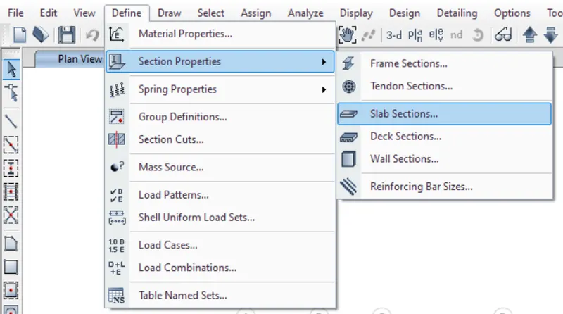
- So in order to add the section properties first we need to go to the define bar then there will be a drop-down list in that list there is an option called Section Properties click on that option from the list after that there will be another list named as the Slab Section just click on that option just as shown in the below given image:
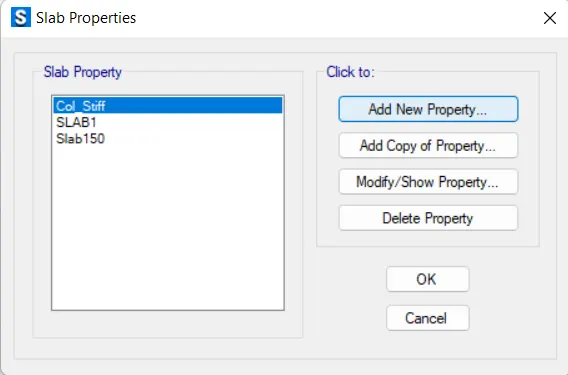
- So now we will be first adding the Pile Cap. So after clicking the option Slab Section then there will be another dialouge box named as the slab properties in that dialouge box there will be another option called Add New Property just click on that option just as shown in the below given image:
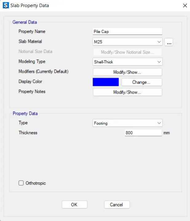
- Then there will be another dialouge box named as th Slab Property Data, in that dialouge box fill the data just as shown in the below given image:
- PILECAP of 800mm Thickness:
- PILES of 500 mm Diameter:

- STIFF COLUMN SECTION:
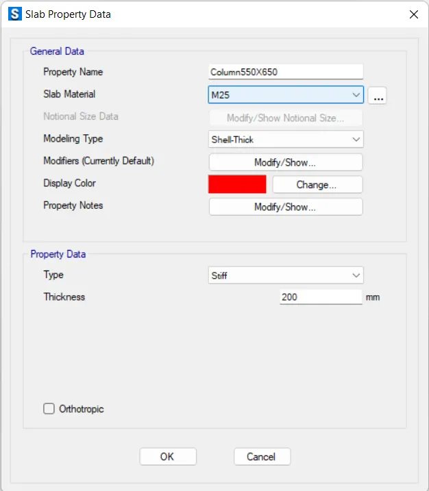
FRAME SECTION FOR TIE BEAMS:
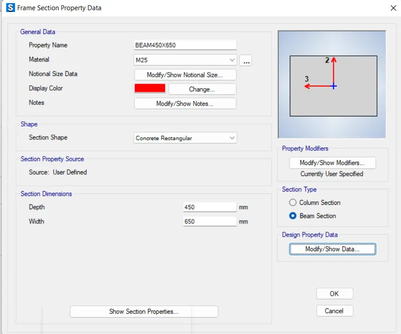
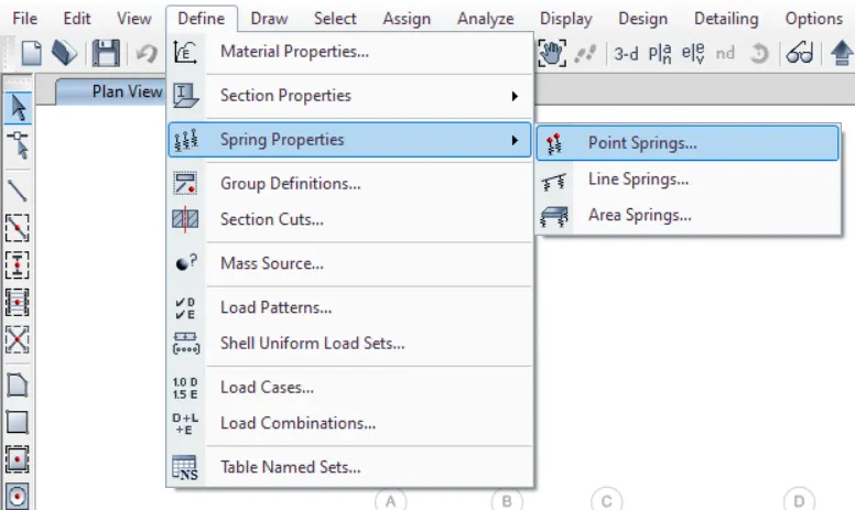
- After that we have to define the Point Spring property and in order to do that just go to the option Define and then there will be a drop-down list and in that list there is an option called Spring properties click on that option and after that there will be another list in that list click on the option Point Spring just click on that option as shown in the below given image:
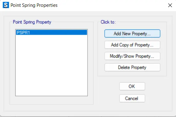
- After this there will be another dialouge box named as the Point Spring Properties,in that dialouge box there is an option called Add New Property just as shown in the below gien image:
- And then there will be another dialouge box named as Point Speing Property Data in that dialouge box fill the data just as shown in the below given image:
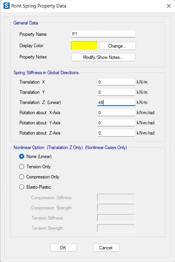
- After that select the Quick areas around the point,then there will be a dialouge box and in that dialouge box give the shape of the object as Rectangle slab and give the properties of Pile slab.
- Here we will be using three sizes of footing i.e 2.5X2.5m,6.5X4.5m and 6.5X6.5m.
- Place all the columns using the above procedure in order to create different sizes of footing.
- Now draw the slab using the quick tool and after creating the slab for the footing now we have to draw the piles just as shown in the below given image: 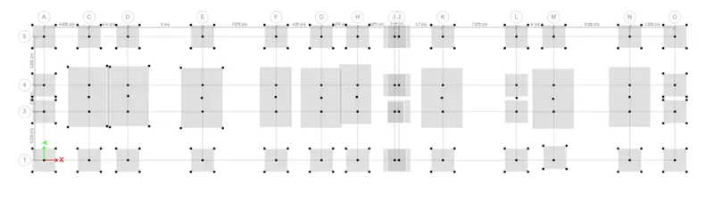
Columns also have been placed as shown in the below given image:
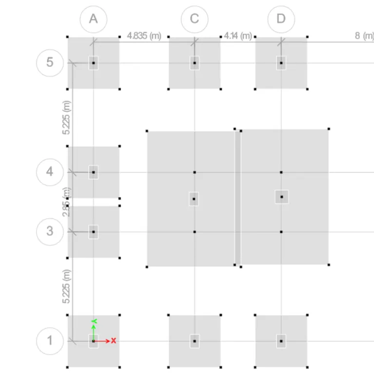
- After assigning the columns assign the piles just as shown in the below given image:
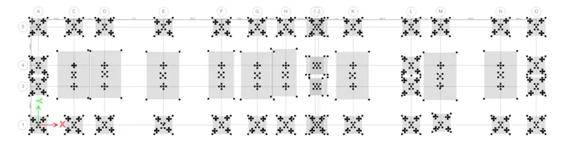
Now we have assign the spring constant also just as shown in the below image:
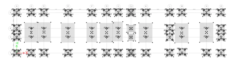
- So after assigning the piles and the columns now we can do the run analysis.Below is the image of the part of the plan:
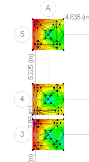
- And after perform the run analysis we have to do some checks on the models.
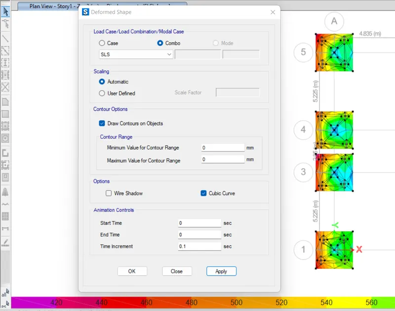
CHECK FOR SETTLEMENT:
-According to the code book a total settlement of 25 mm is allowable not more than that. So the allowable settlement in our case is less than the permissible allowable limit. Hence OK.
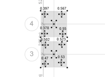
CHECK FOR PUNCHING SHEAR:
- According to the IS code the punching value should not cross unit value,so in our case the punching shear value is less than the unit value.Hence OK.
The Hostel building has been designed and analysed by the SAFE software successfully.