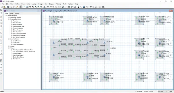
Project 2_Design & Analysis of a Hostel building at Guwahati, Assam
In this project, participants will get to experience the entire design process from modelling, analysis, design, and preparation of construction drawings. The architectural drawings of a G+3 RCC building is provided. The following information on the building is to be used:
Location – Guwahati, Assam
Function – Hostel block in an academic instituteThe walls will be made of AAC blocks. Other loadings are to be calculated as per the architectural drawings.
The buildings rests on type 3 soil. Piles of length 10 meters and 500 mm diameter with a load-carrying capacity of 280 KN is to be used.
The ground floor level will be at a height of 2 meters above the existing site level to avoid floodwater enter the building.
M25 grade of concrete with Fe500 for longitudinal reinforcement and Fe 415 for shear reinforcement is to be used.
The following design IS codes will be required for reference:
IS 875 part 1
IS 875 part 2
IS 13920
IS 1893
IS 2911 part 2
IS 456
SP 34
Students will have to produce the following:
Etabs model for the two blocks on either side of the expansion gap
Foundation details illustrating the pile & pile cap reinforcement
Tie beam details connecting the pile caps
Column reinforcement
Framing plan for typical floor
Beam reinforcements for ground floor
Aim:
Creating the ETABS AND safe model.
Procedure:
I. Set the parameters in the etabs
II.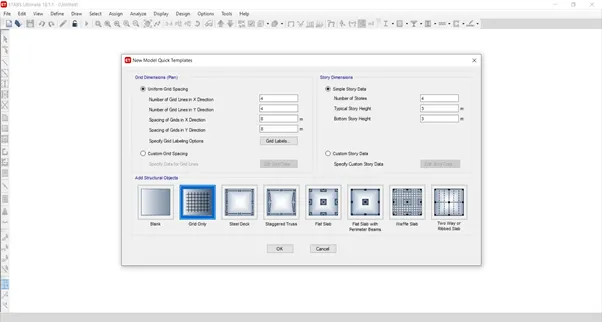
III. Set the levels and grids
IV.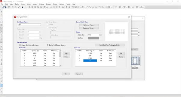
V. Enter the story data
VI.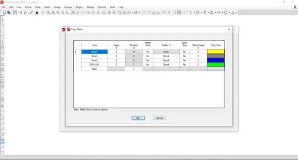
VII. Grids are ready
VIII.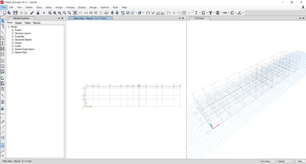
IX. Define the materials
X.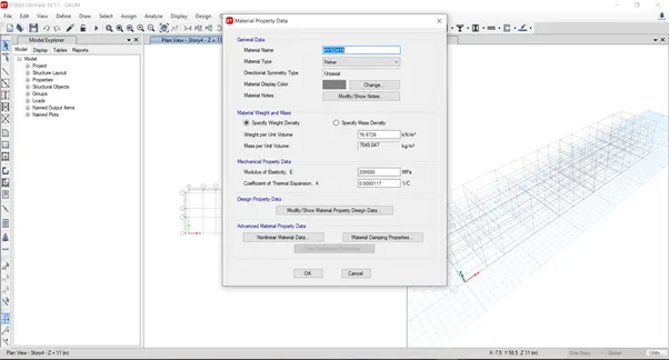
XI.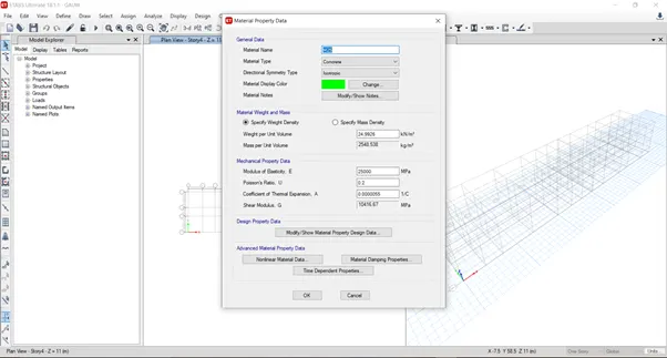
XII. All required materials are defined
XIII.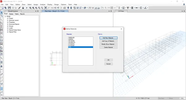
XIV. Define the section
XV.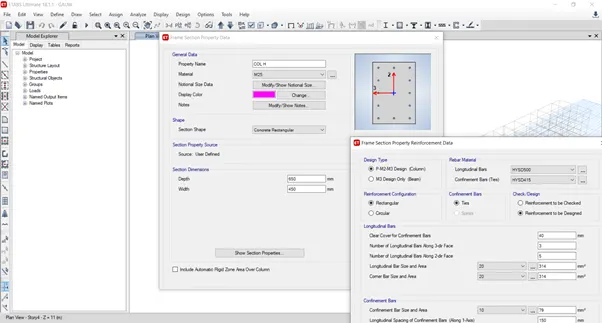
XVI. Define beam
XVII.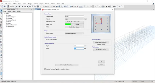
XVIII. Define slab properties
XIX.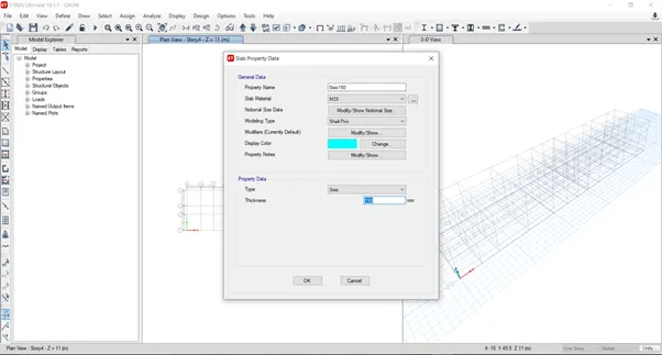
XX. Quick draw beam
XXI. BEAMS
XXII.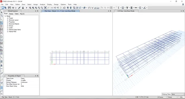
XXIII. Draw columns
XXIV. COLUMNS
XXV.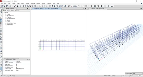
XXVI. Draw slabs
XXVII.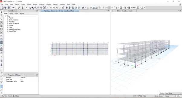
XXVIII. In the base level assign the restraints
XXIX.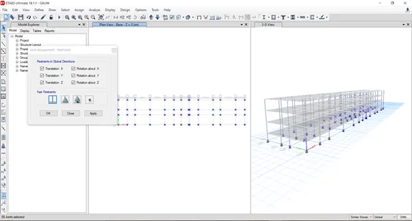
XXX. Define the load patterns
XXXI.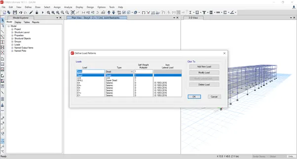
XXXII. Define the seismic loads
XXXIII.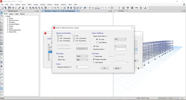
XXXIV. Define the masssource
XXXV.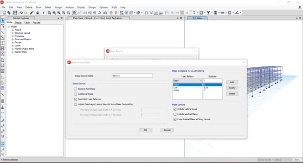
XXXVI. According to the code loads were assigned
XXXVII.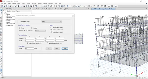
XXXVIII. Define live load as the surface load
XXXIX.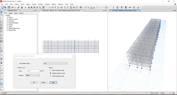
XL. Define the load combinations
XLI.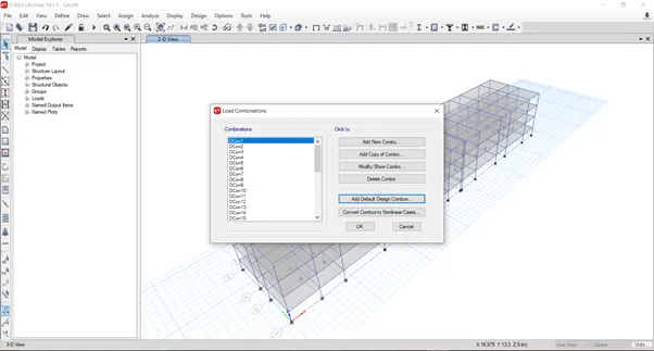
XLII. Check model
XLIII.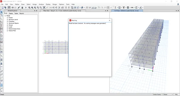
XLIV. Run analysis
XLV.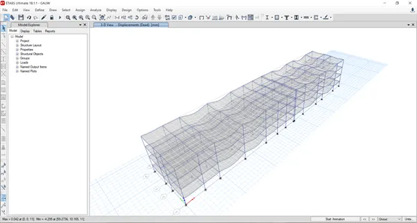
XLVI. Design model
XLVII.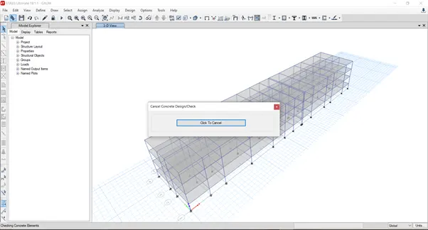
XLVIII.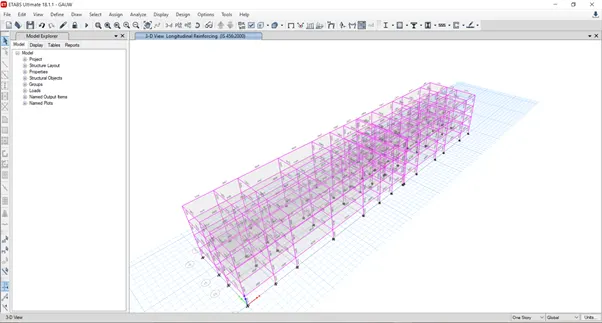
XLIX. Required reinforcement is displayed
L.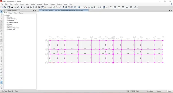
LI. Calculations can be made for the reinforcement as the required reinforcement is displayed.
SAFE
LII. Foundation design
LIII. Export the file from etabs
LIV.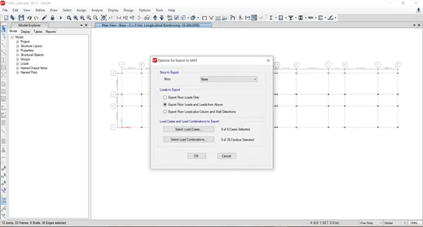
LV. Next open the safe file and import the exported file
LVI.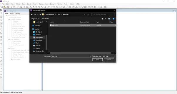
LVII.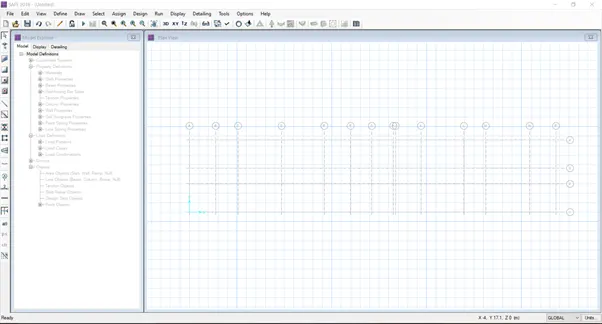
LVIII. Assigned load check
LIX.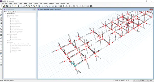
LX. Define materials
LXI.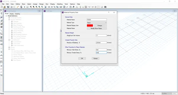
LXII.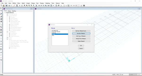
LXIII. Define the slab properties
LXIV.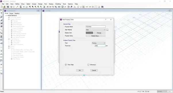
LXV. Define the soil
LXVI.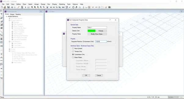
LXVII. Draw the points for the reference of the pile
LXVIII.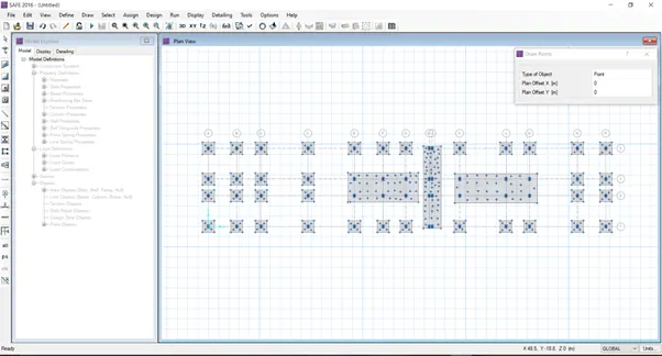
LXIX. Draw piles
LXX. And assign the point springs
LXXI.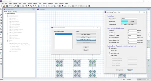
LXXII.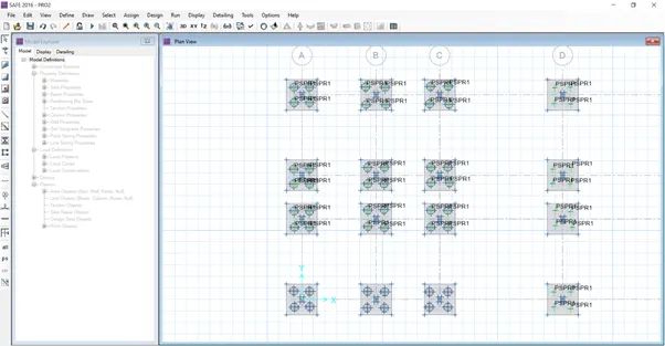
LXXIII. Draw columns below the loads
LXXIV.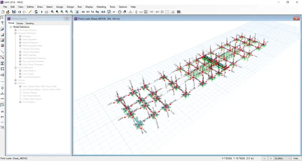
LXXV. Run the model
LXXVI. Display the deflection
LXXVII.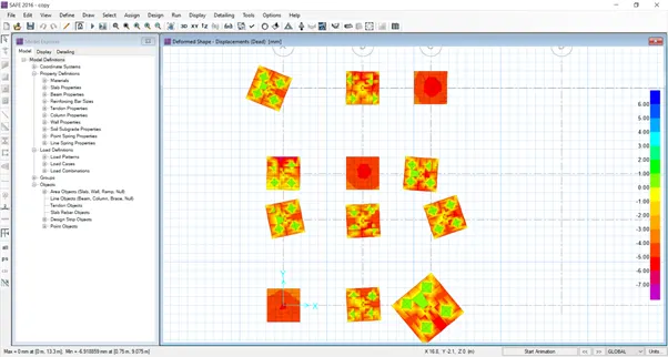
LXXVIII. Reactions
LXXIX.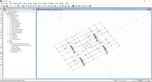
LXXX. Punching shear
LXXXI.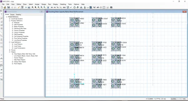
LXXXII. Design reinforcement
LXXXIII. Since load was heavy the model divided to 3 pasts and analysis was done
LXXXIV.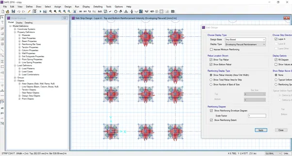
LXXXV.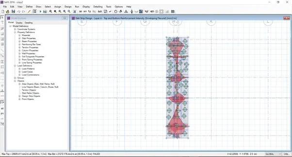
LXXXVI.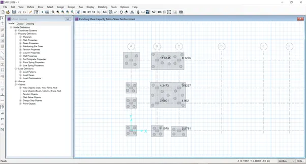
LXXXVII.