Creating a Floor plan, Footing detail and Isometric view using AutoCad
1. P1
Aim:
Sketch the given footing drawing in the AutoCAD with the help of the useful commands and coordinate systems
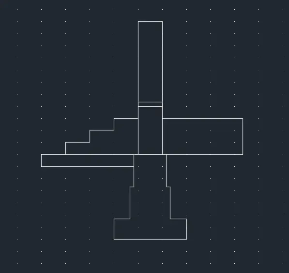
In the command prompt write
I. In command bar type L
Which give line curser, now in command bar type as below
II. In the command prompt write (specify first point: 5,5)
III. In the command prompt write (next point: @1.15<180)
IV. In the command prompt write(ds) which open draft settings here, click on the snap on and give the snap x spacing as 0.3 and snap y spacing as 0.15 respectively for the grid spacing also
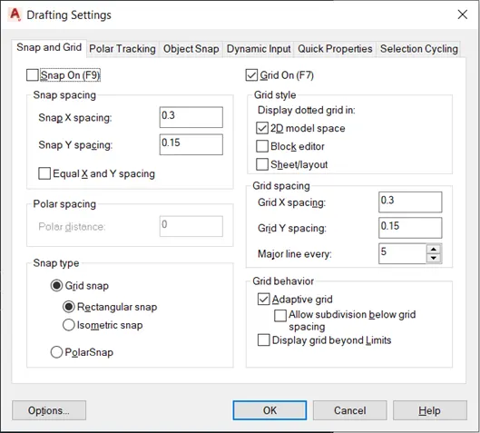
V. With hep of the snaping draw the steps in the footing for the 5 steps
VI. In command bar type L, which give line curser, now in command bar type as below and select the end point
VII. In the command prompt write (next point: @0.05<90)
VIII. In the command prompt write (next point: @1<90)
IX. In the command prompt write (next point: @0.3<0)
X. In the command prompt write (next point: @1<270)
XI. In the command prompt write (next point: @0.05<270)
XII. In the command prompt write (next point: @1<0)
XIII. In the command prompt write (next point: @0.6<270)
XIV. In the command prompt write (next point: @1<180)
XV. In the command prompt write (next point: @0.05<180)
XVI. In the command prompt write (next point: @0.3<180)
XVII. In the command prompt write (next point: @0.05<180)
XVIII. In the command prompt write (next point: @1.15<180)
XIX. In the command prompt write (o select the offset)
Specify the offset distance: 0.6, Select the 0.3 m at bottom line and in the vertical direction
Again, XVI. In the command prompt write (o select the offset)
Specify the offset distance: 0.05, Select the last drawn line and in the vertical direction
XX. Select the edge of the 0.05line drawn last as the start point of the line command
XXI. In the command prompt write (next point: @0.4<270)
XXII. In the command prompt write (next point: @0.05<180)
XXIII. In the command prompt write (next point: @0.4<270)
XXIV. In the command prompt write (next point: @0.2<180)
XXV. In the command prompt write (next point: @0.25<270)
XXVI. In the command prompt write (next point: @0.9<0)
XXVII. In the command prompt write (next point: @0.25<90)
XXVIII. In the command prompt write (next point: @0.2<180)
XXIX. In the command prompt write (next point: @0.4<90)
XXX. In the command prompt write (next point: @0.05<180)
XXXI. In the command prompt write (next point: @0.4<90)
Result:
Required footing drawing with the dimensions provided was obtained.
2. P2
Aim:
Sketch the given footing drawing in the AutoCAD with the help of the useful commands and coordinate systems
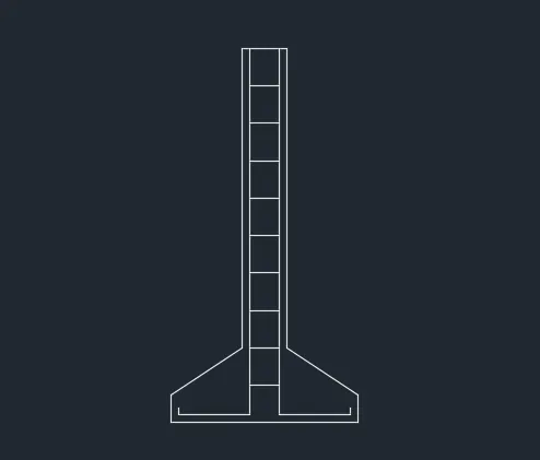
I. In the command prompt write In command bar type L
Which give line curser, now in command bar type as below
II. In the command prompt write (specify first point: 2,2)
III. In the command prompt write (next point: @1<0)
IV. In the command prompt write (next point: @0.15<90)
V. In the command prompt write (next point: 2.6,2.4)
VI. In the command prompt write (next point: @1.6<90)
VII. In the command prompt write (next point: @0.68<180)
VIII. In the command prompt write (next point: @1.6<270)
IX. In the command prompt write (next point: 2,2.16)
X. In the command prompt write (next point: @1<0)
XI. In the command prompt write (next point: C)
XII. In the command prompt write In command bar type L
Which give line curser, now in command bar type as below
XIII. In the command prompt write (specify first point: 2.42,4)
XIV. In the command prompt write (next point: @1.96<270)
XV. In the command prompt write (next point: @0.38<180)
XVI. In the command prompt write (next point: @0.04<90)
XVII. In the command prompt write Line command bar type L
Which give line curser, now in command bar type as below
XVIII. In the command prompt write (specify first point: 2.66,4)
XIX. In the command prompt write (next point: @1.96<270)
XX. In the command prompt write (next point: @0.38<180)
XXI. In the command prompt write (next point: @0.04<90)
XXII. In the command prompt write in command bar type L
Which give line curser, now in command bar type as below
XXIII. In the command prompt write (specify first point: 2.42,3.8)
XXIV. In the command prompt write (next point: @0.2<0)
XXV. Select the last line and enter co in the command prompt then, select array and give number of repetitions as 9 and specify the second point as (0.2<270)
Result:
Required footing drawing with the dimensions provided was obtained.
3. P3
Aim:
Draw the layout of the plan as shown in the AutoCAD with the help of the command prompt.
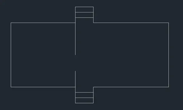
I. In the command prompt write In command bar type L Which give line curser, now in command bar type as below
II. In the command prompt write (specify first point: 2,2)
III. In the command prompt write (next point: @3.6<180)
IV. In the command prompt write (next point: @3.6<90)
V. In the command prompt write (next point: @3.6<0)
VI. In the command prompt write (next point: @0.3<90)
VII. In the command prompt write (next point: @0.3<90)
VIII. In the command prompt write (next point: @0.3<90)
IX. In the command prompt write (next point: @1<0)
X. In the command prompt write (next point: @0.3<270)
XI. In the command prompt write (next point: @0.3<270)
XII. In the command prompt write (next point: @0.3<270)
XIII. In the command prompt write (next point: @4.2<0)
XIV. In the command prompt write (next point: @3.6<270)
XV. In the command prompt write (next point: @4.2<180)
XVI. In the command prompt write (next point: @0.3<270)
XVII. In the command prompt write (next point: @0.3<270)
XVIII. In the command prompt write (next point: @0.3<270)
XIX. In the command prompt write (next point: @1<180)
XX. In the command prompt write (next point: @0.3<90)
XXI. In the command prompt write (next point: @0.3<90)
XXII. In the command prompt write (next point: @0.3<90)
XXIII. In the command prompt write (next point: @0.9<90)
XXIV. Enter
XXV. In the command prompt write In command bar type L Which give line curser, now in command bar type as below
XXVI. In the command prompt write (specify first point: 2,5.6)
XXVII. In the command prompt write (next point: @1.8<270)
XXVIII. enter
XXIX. In the command prompt write In command bar type L Which give line curser, now in command bar type as below
XXX. In the command prompt write (specify first point: 2,6.2)
XXXI. In the command prompt write (next point: @1<0)
XXXII. Type o in command prompt for offset and specify distance as 0.3 and select the last drawn line and the direction it should be offset
XXXIII. In the command prompt write In command bar type L Which give line curser, now in command bar type as below
XXXIV. In the command prompt write (specify first point: 2,1.7)
XXXV. In the command prompt write (next point: @1<0)
XXXVI. Type o in command prompt for offset and specify distance as 0.3 and select the last drawn line and the direction it should be offset
XXXVII. Enter
Result:t
The required plan of the layout is obtained in the drawing
4. P4
Aim:
Draw the load bearing wall sectional view in the AutoCAD
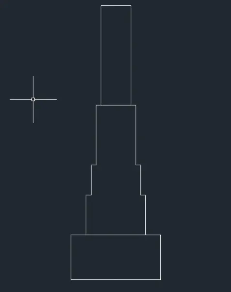
I. In the command prompt write In command bar type L Which give line curser, now in command bar type as below
II. In the command prompt write (specify first point: 2,2)
III. In the command prompt write (next point: @0.45<0)
IV. In the command prompt write (next point: @0.45<90)
V. In the command prompt write (next point: @0.15<0)
VI. In the command prompt write (next point: @0.4<90)
VII. In the command prompt write (next point: @0.05<0)
VIII. In the command prompt write (next point: @0.3<90)
IX. In the command prompt write (next point: @0.05<0)
X. In the command prompt write (next point: @0.6<90)
XI. In the command prompt write (next point: @0.05<0)
XII. In the command prompt write (next point: @1<90)
XIII. In the command prompt write (next point: @0.15<0)
XIV. Now select the all lines and select the mirrior option by typing MI in command prompt and draw the axis from end point to start point of line next for the erase click no and press enter.
XV. In the command prompt write In command bar type L Which give line curser, now in command bar type as below
XVI. In the command prompt write (specify first point: 2.15,2.45)
XVII. In the command prompt write (next point: @0.6<0)
XVIII. Enter
XIX. In the command prompt write In command bar type L Which give line curser, now in command bar type as below
XX. In the command prompt write (specify first point: 2.3,3.75)
XXI. In the command prompt write (next point: @0.3<0)
XXII. Enter
Result:
Required load bearing wall with showing the details of the footing is obtained.
5. P5
Aim:
Drawing of the isometric view of the steps in AutoCAD
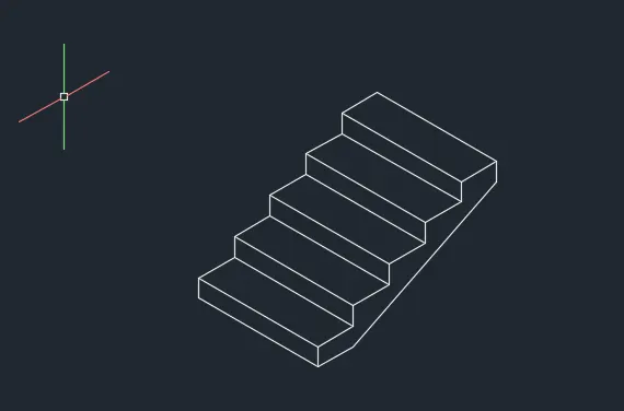
I. Select the isometric cursor i.e., isoplane left and with line command draw the line of 1m to the left and continue it to the 0.15 downward and 1m to right and 0.15 to top.
II. Next select the isoplane right draw two line to the right direction of 0.3m from top corners of the rectangle respectively
III. Enter
IV. Now type the co in command prompt and select everything and specify the base point as the bottom corner of the rectangle
V. Now, drag it to the extended line point and click with help of the snapping repeat it for the 4 times so that 5 steps are formed
VI. At last join the extended lines and with help of the isoplane left draw line of the 0.15 towards bottom from the right corner
VII. Change to the isoplane right draw line of the 0.3m from bottom towards right and join both the unconnected ends.
VIII. Enter
Result:
Isometric steps were obtained in the AutoCAD drawing form.
6. P6
AIM:
Detailed procedure of drawing the gable wall in the AutoCAD isometric view
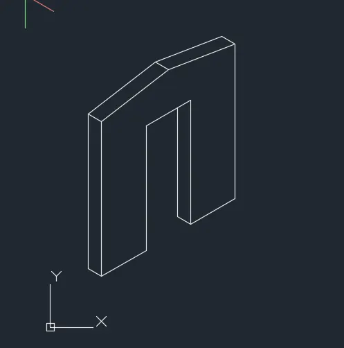
I. Select the isometric cursor i.e., isoplane left and with line command draw the line of 0.3m to the left and in command prompt type (@3<90)
II. in command prompt type (@0.3<330)
III. in command prompt type (@3<270)
IV. change to isoplane right in command prompt type (@1<30)
V. in command prompt type (@2.42<90)
VI. in command prompt type (@1<30)
VII. in command prompt type (@2.42<270)
VIII. in command prompt type (@1<30)
IX. in command prompt type (@3<90)
X. change to isoplane left and click on a point where thickness view has to be provided to the door and in command prompt type (@0.3<150)
XI. with help of ortho on join to the above line perpendicularly
XII. from the midpoint of the door draw a line for the reference with length of 0.83 (i.e., 3.24-2.42)
XIII. with the snapping on join the edge lines to the reference line
XIV. select the reference line and erase by typing E in the command prompt.
XV. Provide thickness of 0.3m and again join all the thickness provided.
XVI. Enter
Result:
Gable wall is sketched the isometric AutoCAD