Project 2_Design & Analysis of a Hostel building at Guwahati, Assam
Project 2_Design & Analysis of a Hostel building at Guwahati, Assam
In this project, participants will get to experience the entire design process from modelling, analysis, design, and preparation of construction drawings. The architectural drawings of a G+3 RCC building is provided. The following information on the building is to be used:
- Location – Guwahati, Assam
- Function – Hostel block in an academic institute
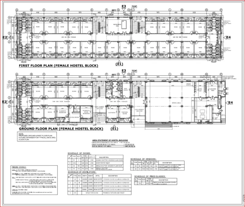
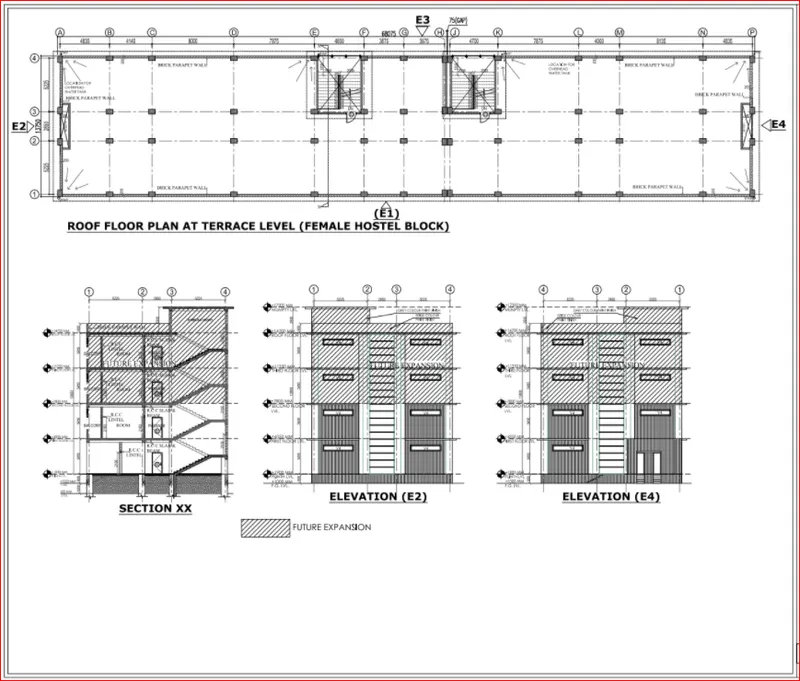
The walls will be made of AAC blocks. Other loadings are to be calculated as per the architectural drawings.
The buildings rests on type 3 soil. Piles of length 10 meters and 500 mm diameter with a load-carrying capacity of 280 KN is to be used.
The ground floor level will be at a height of 2 meters above the existing site level to avoid floodwater enter the building.
M25 grade of concrete with Fe500 for longitudinal reinforcement and Fe 415 for shear reinforcement is to be used.
The following design IS codes will be required for reference:
- IS 875 part 1
- IS 875 part 2
- IS 13920
- IS 1893
- IS 2911 part 2
- IS 456
- SP 34
Students will have to produce the following:
- Etabs model for the two blocks on either side of the expansion gap
- Foundation details illustrating the pile & pile cap reinforcement
- Tie beam details connecting the pile caps
- Column reinforcement
- Framing plan for typical floor
- Beam reinforcements for ground floor
AIM: To design and analysis of G+3 hostel building in etabs and foundation in safe
Introduction:
In this project, participants will get to experience the entire design process from modelling, analysis, design, and preparation of construction drawings. The architectural drawings of a G+3 RCC building is provided. The following information on the building is to be used:
Location – Guwahati, Assam
Function – Hostel block in an academic instituteThe walls will be made of AAC blocks. Other loadings are to be calculated as per the architectural drawings.
The buildings rests on type 3 soil. Piles of length 10 meters and 500 mm diameter with a load-carrying capacity of 280 KN is to be used.
The ground floor level will be at a height of 2 meters above the existing site level to avoid floodwater enter the building.
M25 grade of concrete with Fe500 for longitudinal reinforcement and Fe 415 for shear reinforcement is to be used.
The following design IS codes will be required for reference:
IS 875 part 1
IS 875 part 2
IS 13920
IS 1893
IS 2911 part 2
IS 456
SP 34
Students will have to produce the following:
Etabs model for the two blocks on either side of the expansion gap
Foundation details illustrating the pile & pile cap reinforcement
Tie beam details connecting the pile caps
Column reinforcement
Framing plan for typical floor
Beam reinforcements for ground floor
Procedure:
first create etabs model
step 1: open the etabs software
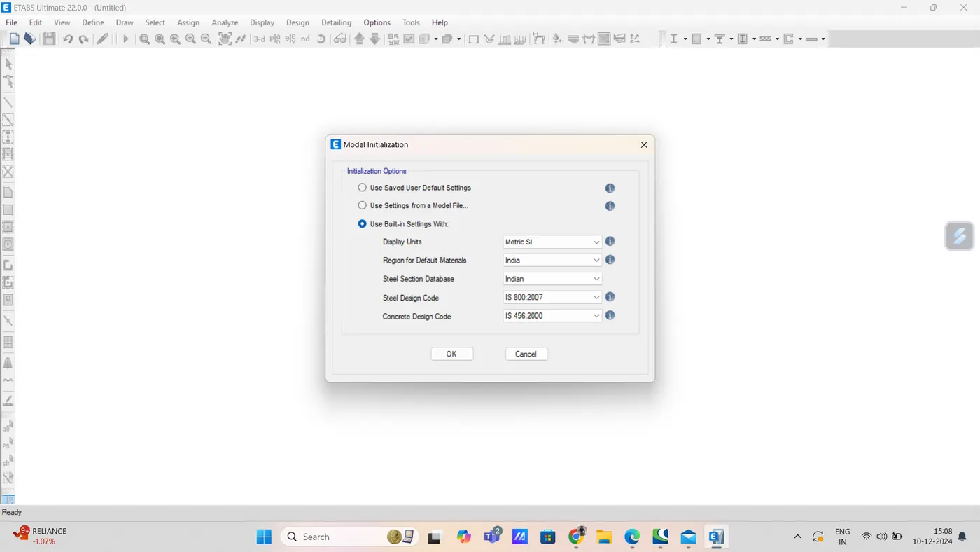
click on built up option from initialization window
then put all correct code
like that
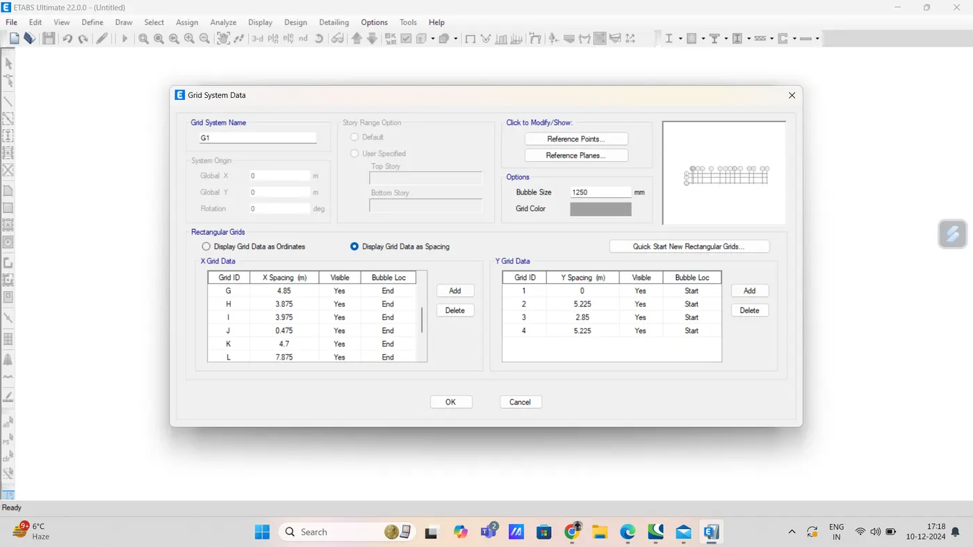
step 2) grid setting
set grid of X direction and Y direction accordingly plan as shown below
now add stories data
like that
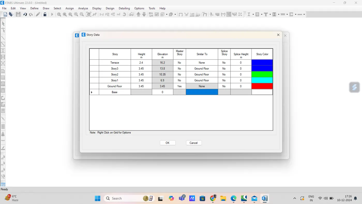
now our frame plan is ready on etabs screen
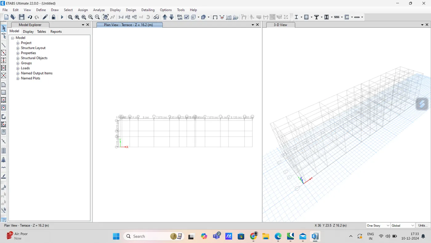
step 3) now define material property
go to define tab and select material option
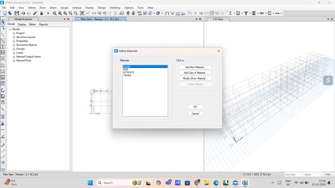
click on add new material option
and add M25 grade concrete
and also, rebar of fe415 and fe500 fck
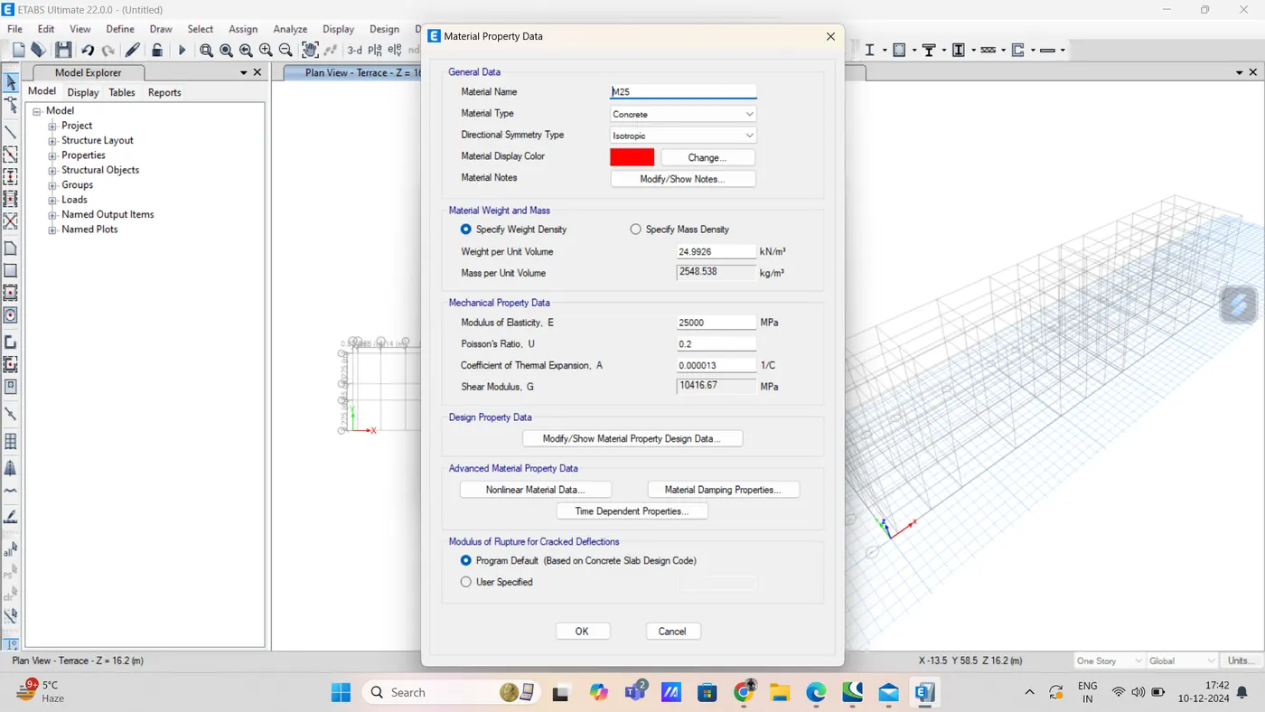
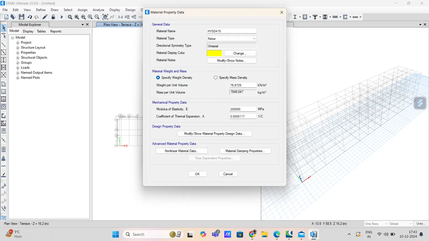
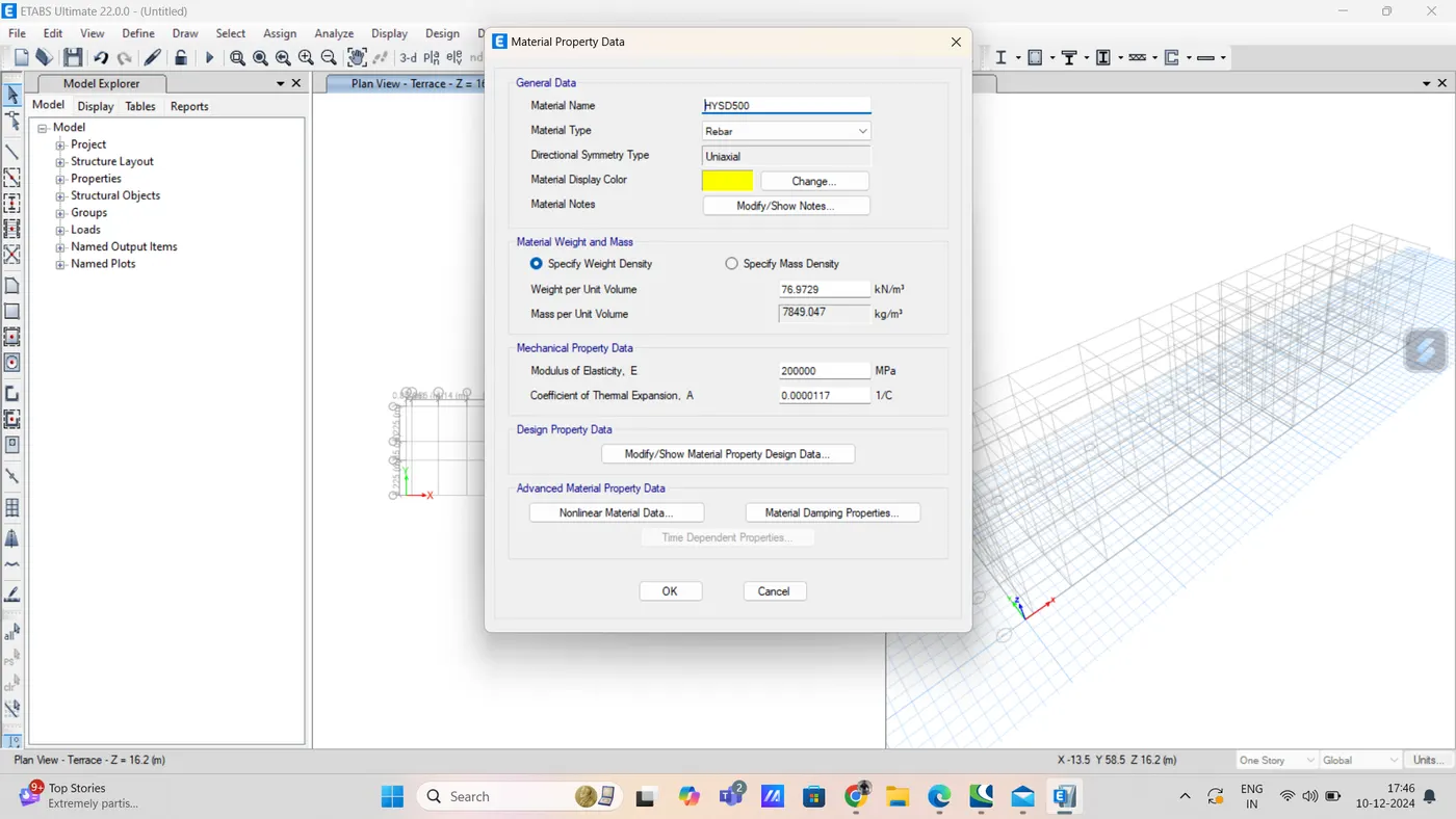
our all material are shown below
step 4) section property
go to define
and click on frame section
then click on add new property
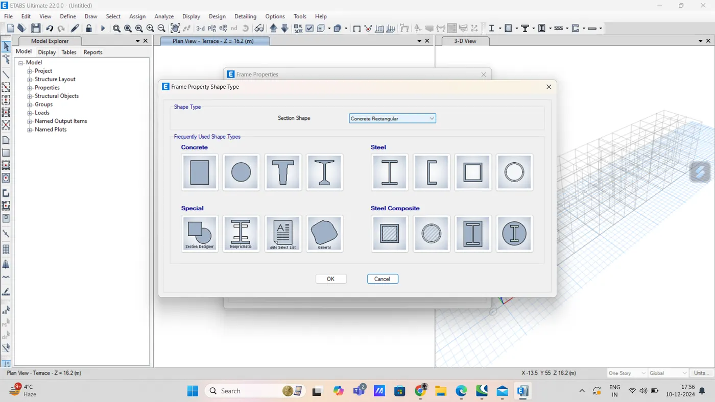
select rectangular section
and press ok
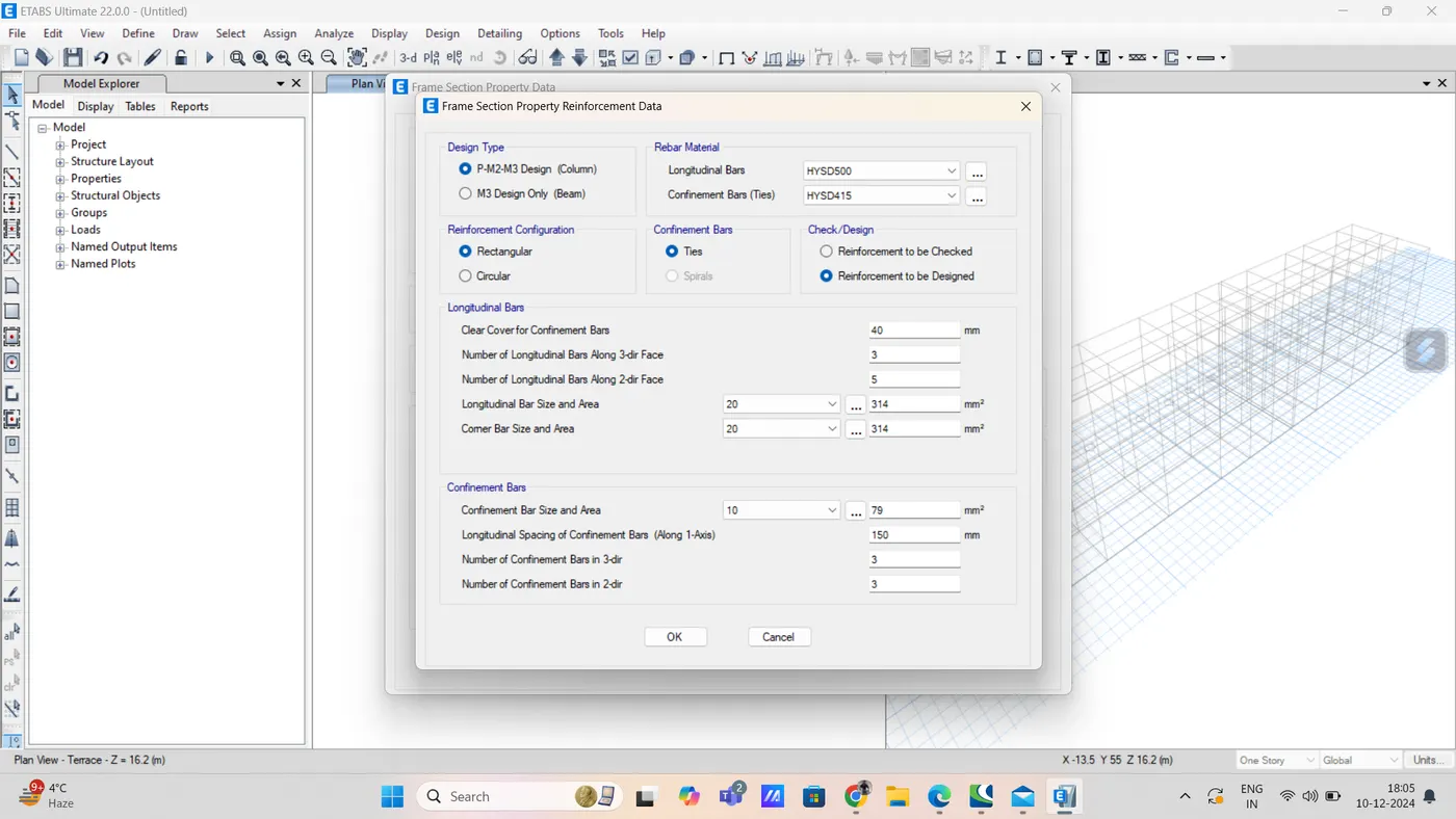
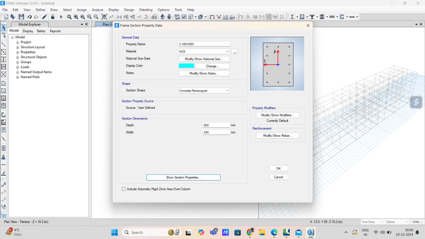
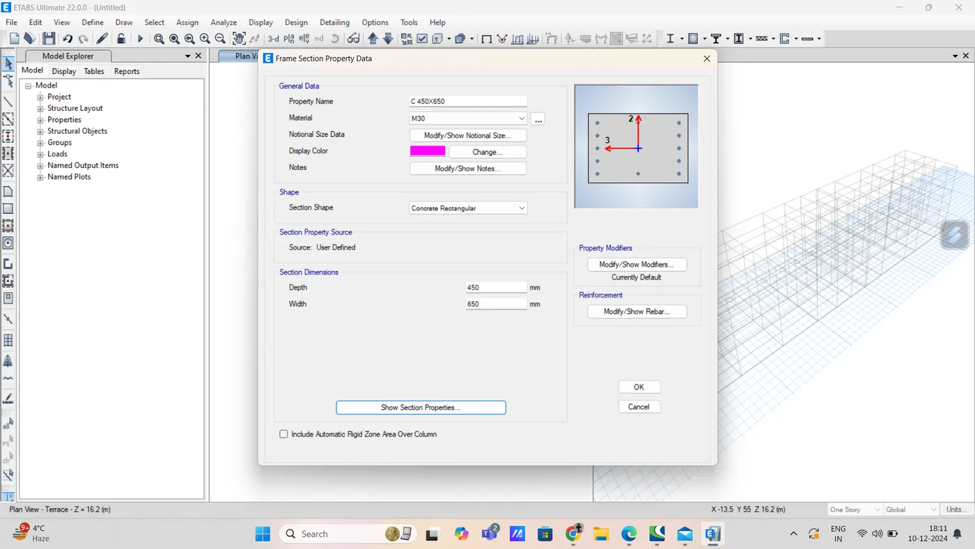
again, add column of size 650X450
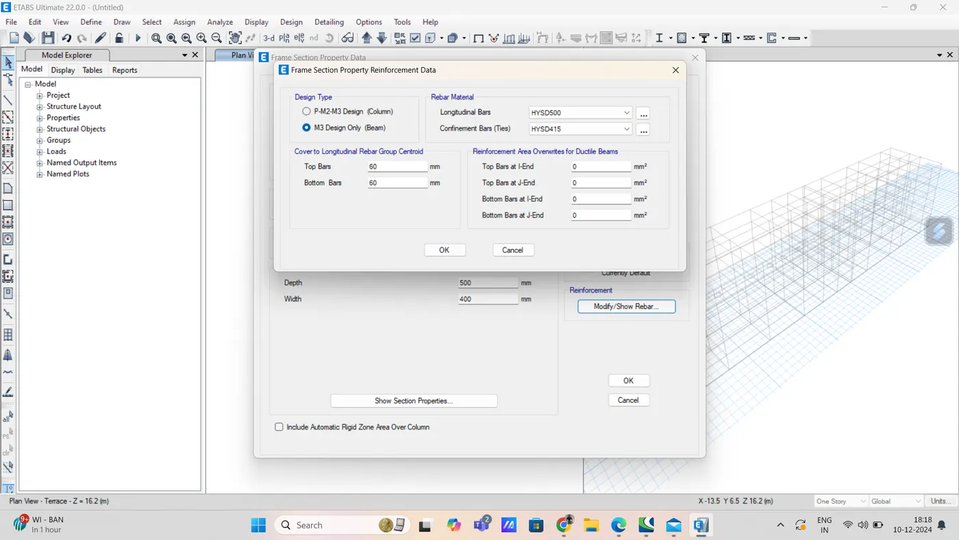
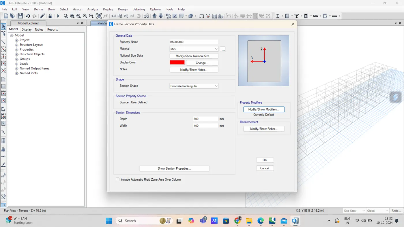
Beam 400 x 500mm
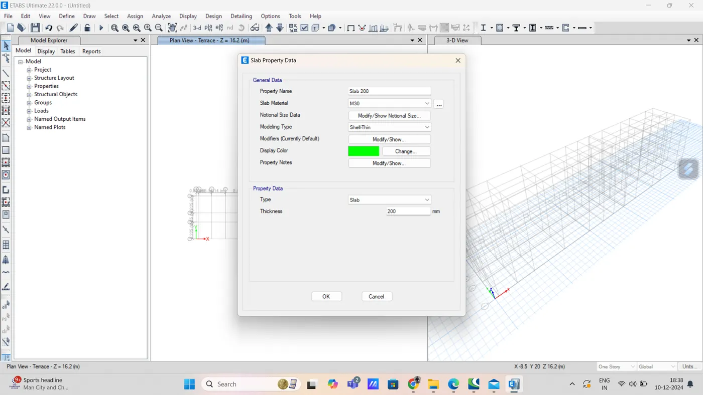
step 5) slab properties
go to define
then select slab section from section properties
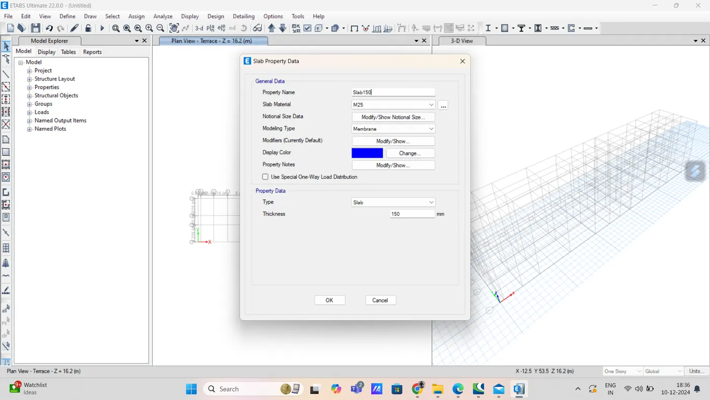
now also take 200 slab thickness separate for staircase
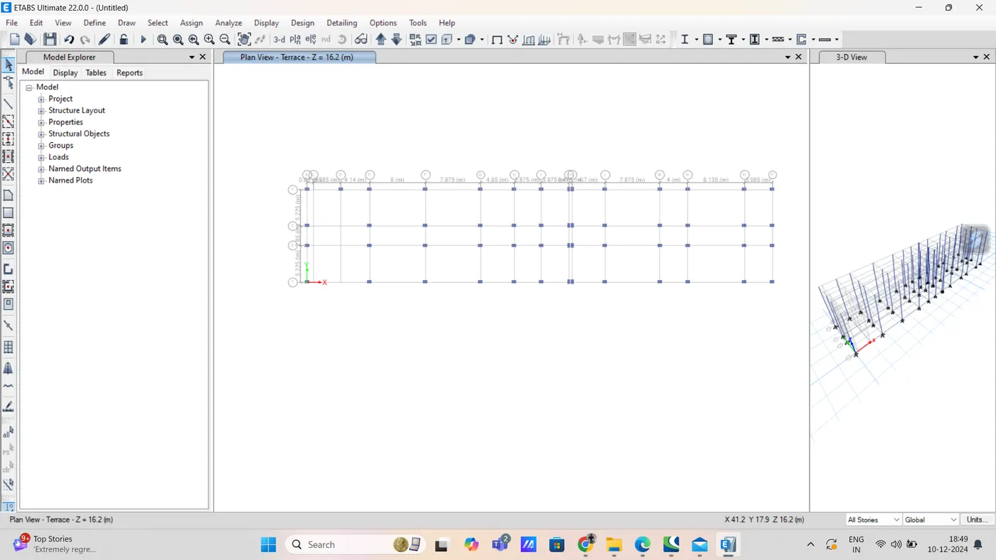
step 6) draw column using quick draw option
step 6)
draw beam B 400X500 to for all stories
by changing working plane as all stories
using quick draw beams
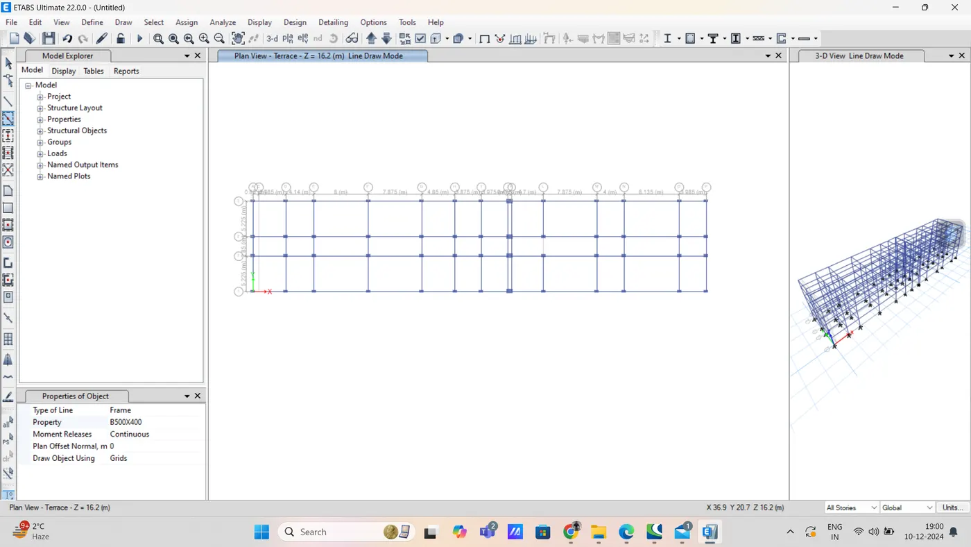
step 7) add slab using quick draw floor/wall option
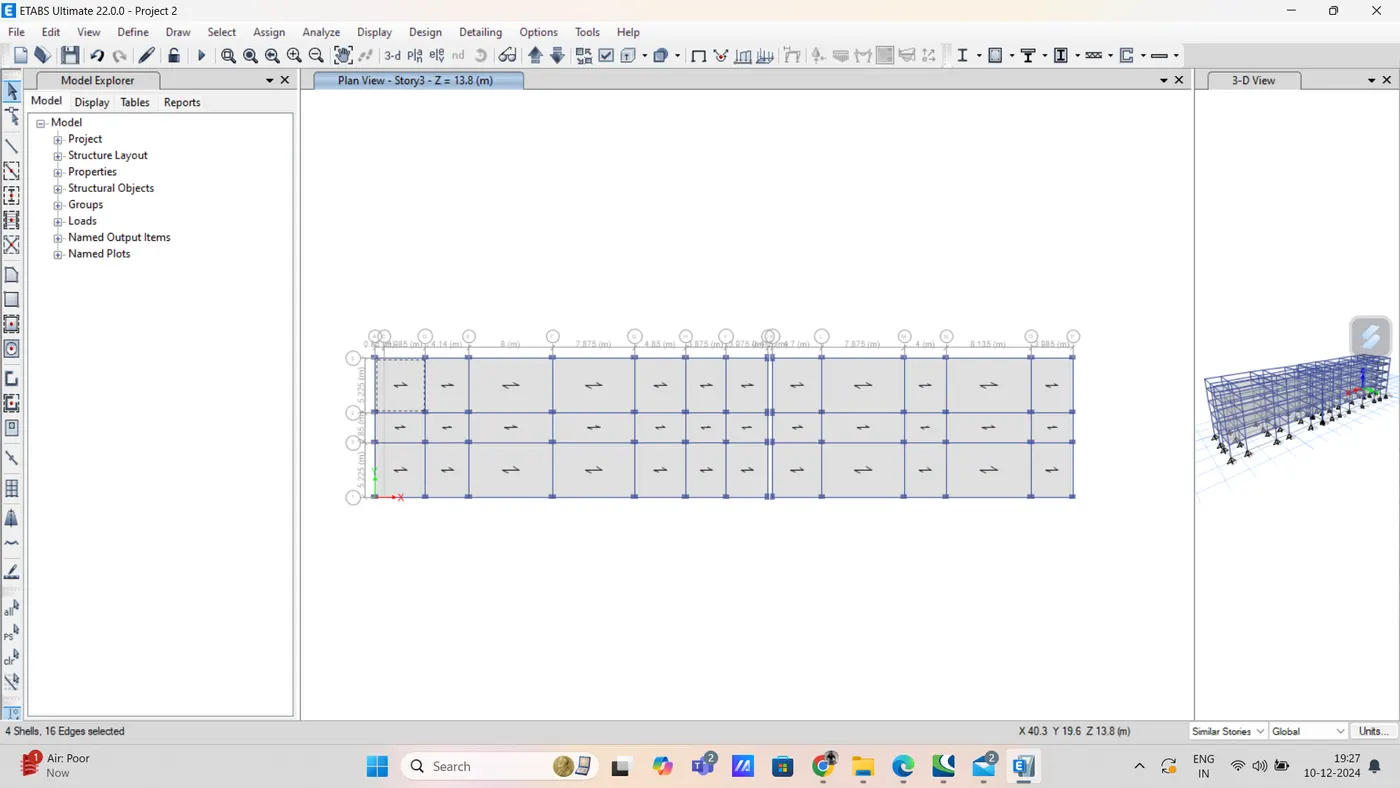
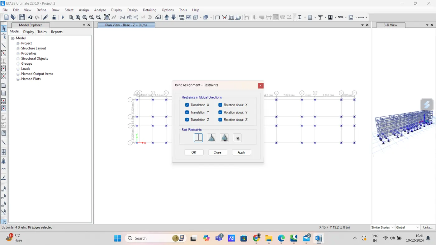
step 8) now go to base plan from plan option
and select all joints
and assign restraint joint option from assign
step 10) now go for load pattern from define option
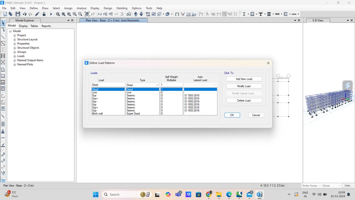
then select EQX and click on modify lateral load, new tab will appear
in that select X direction as per IS 800-2002, seismic zone factor for Guwahati, aasam is taken as 0.36 as mentioned below
select site type as 3
click Ok
similarly do for all seismic load
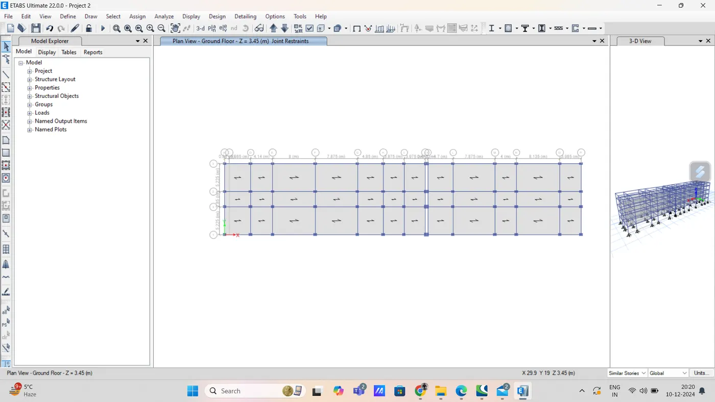
then click to assign option assign option select shell load, from shell load select uniform option
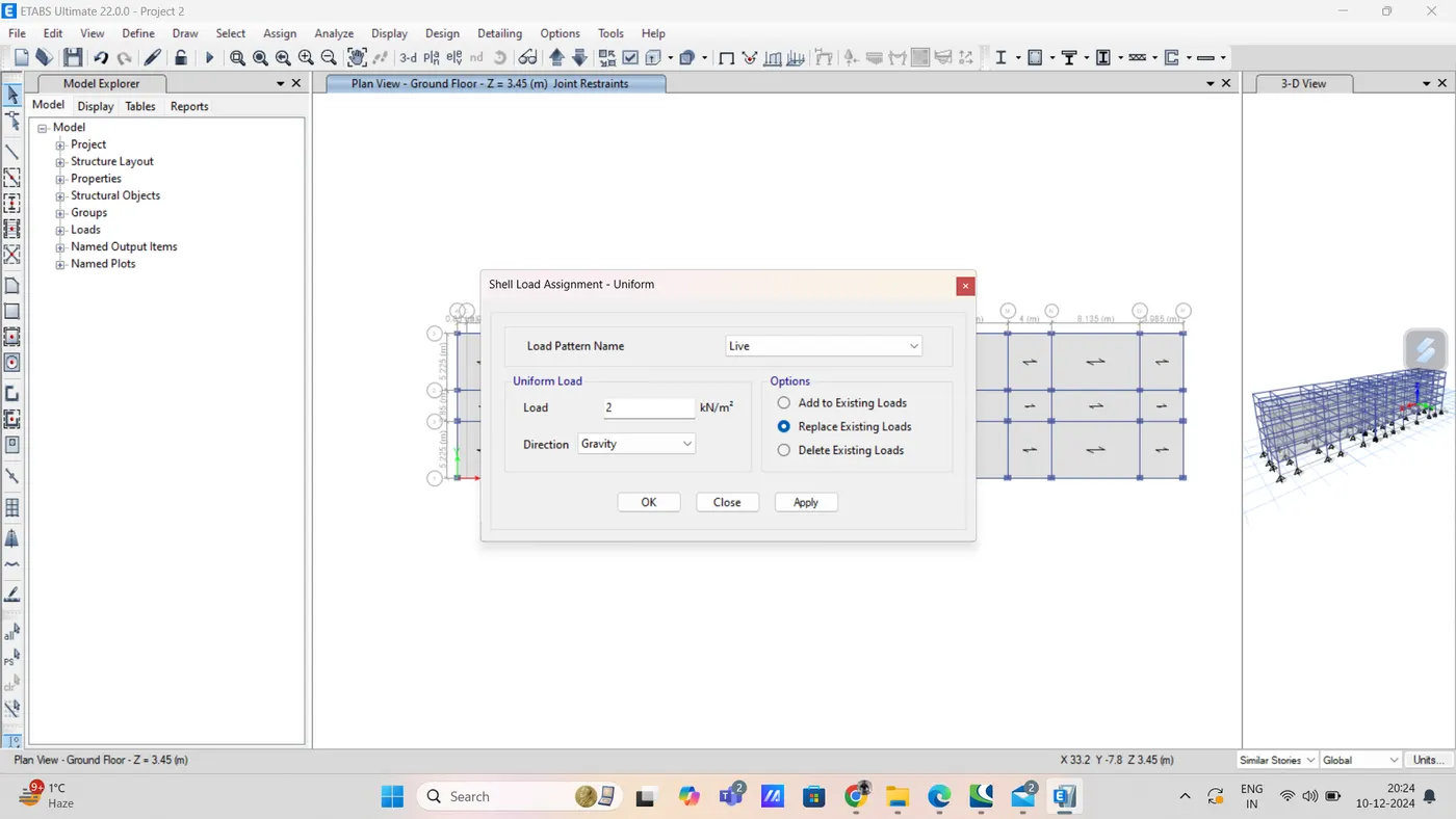
and click ok
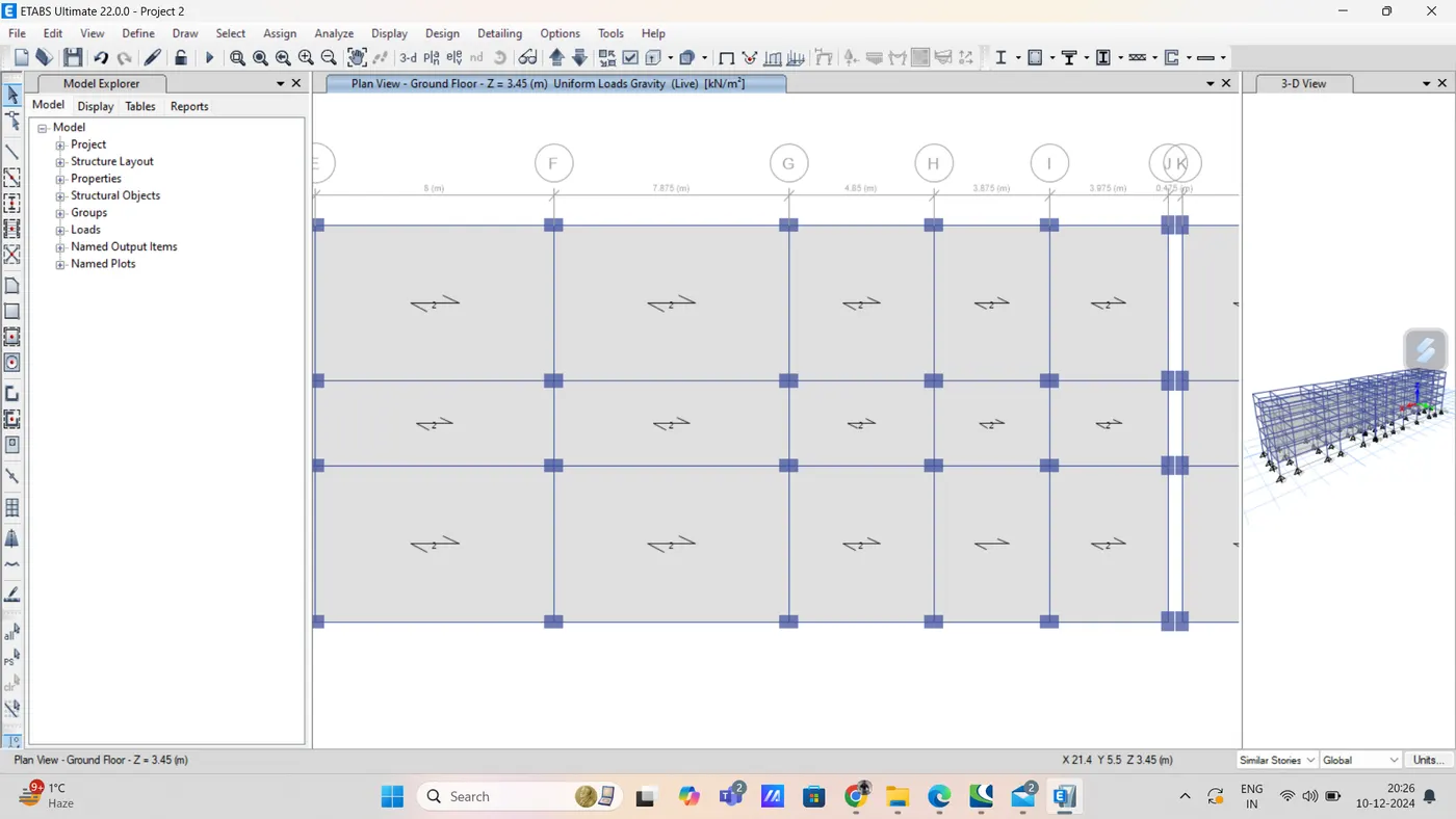
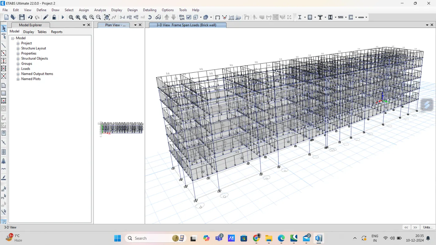
step 12) assign load on beam
select object type option then select beam and click on select button
and then close it
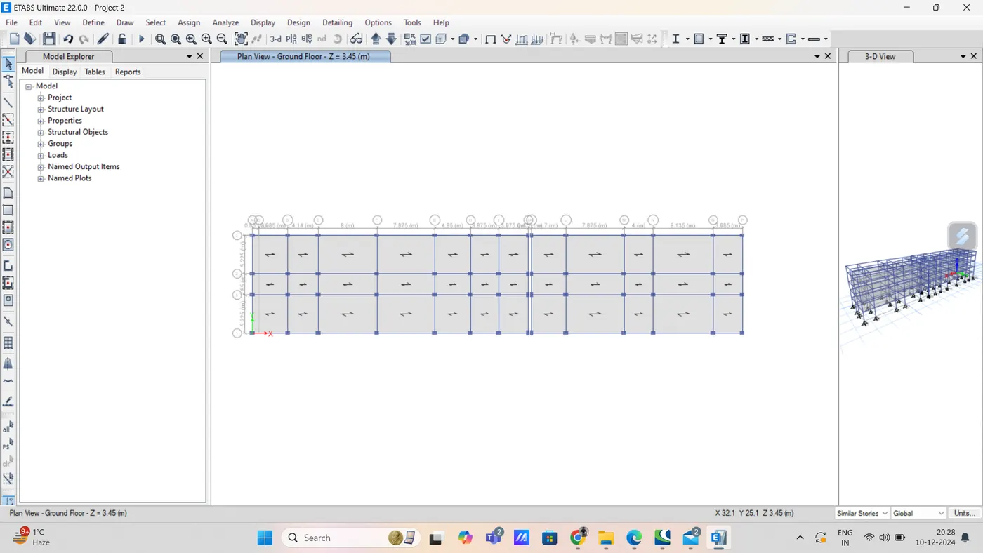
now click on assign option and then select frame load
click on distributed load option
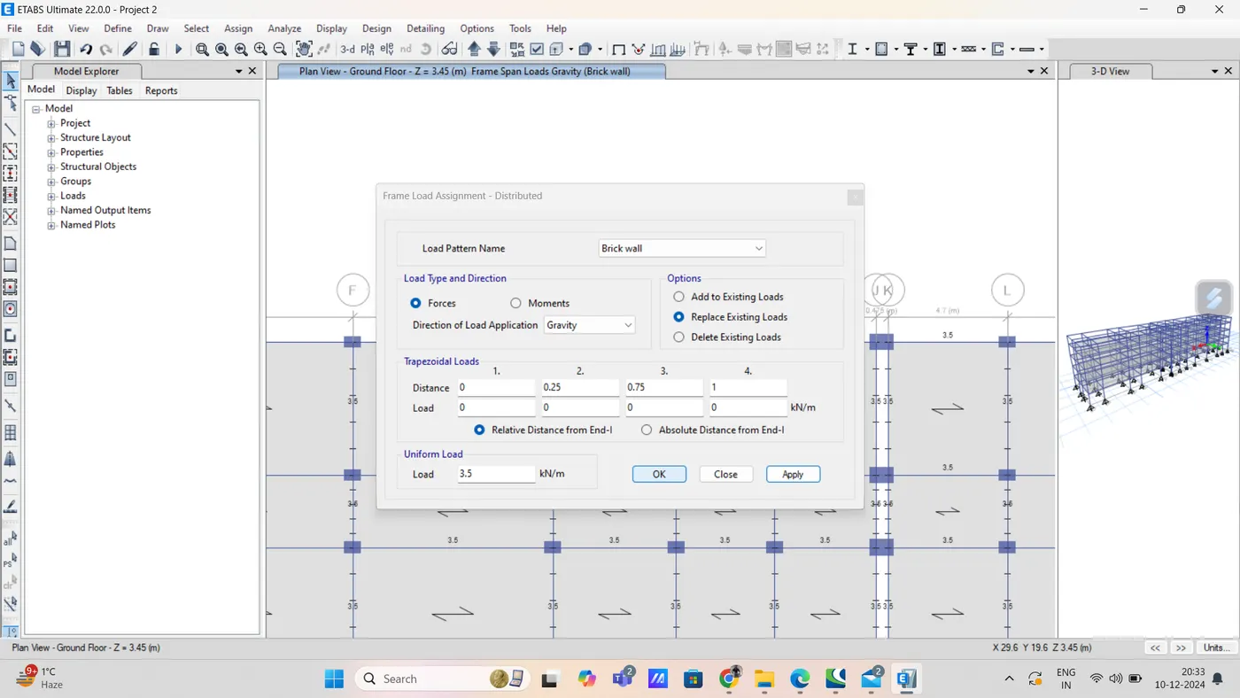
step 13) mass source
from define option select mass source
as shown below
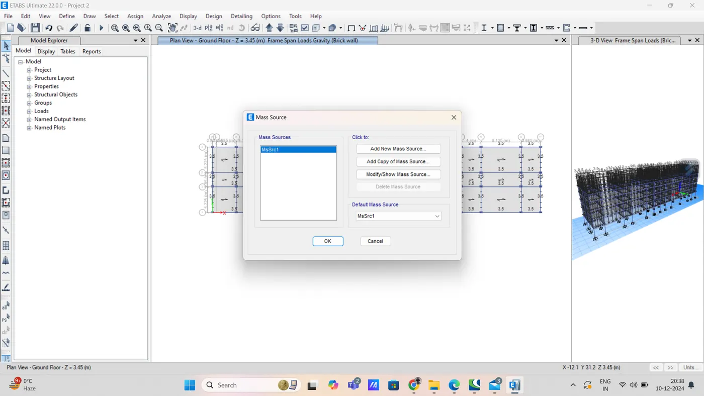
in that click on modify mass source
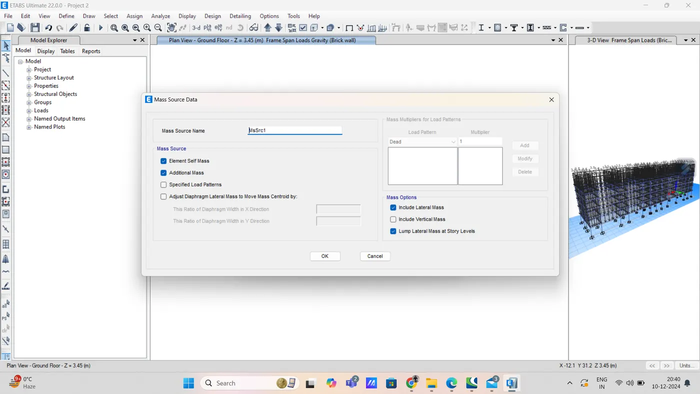
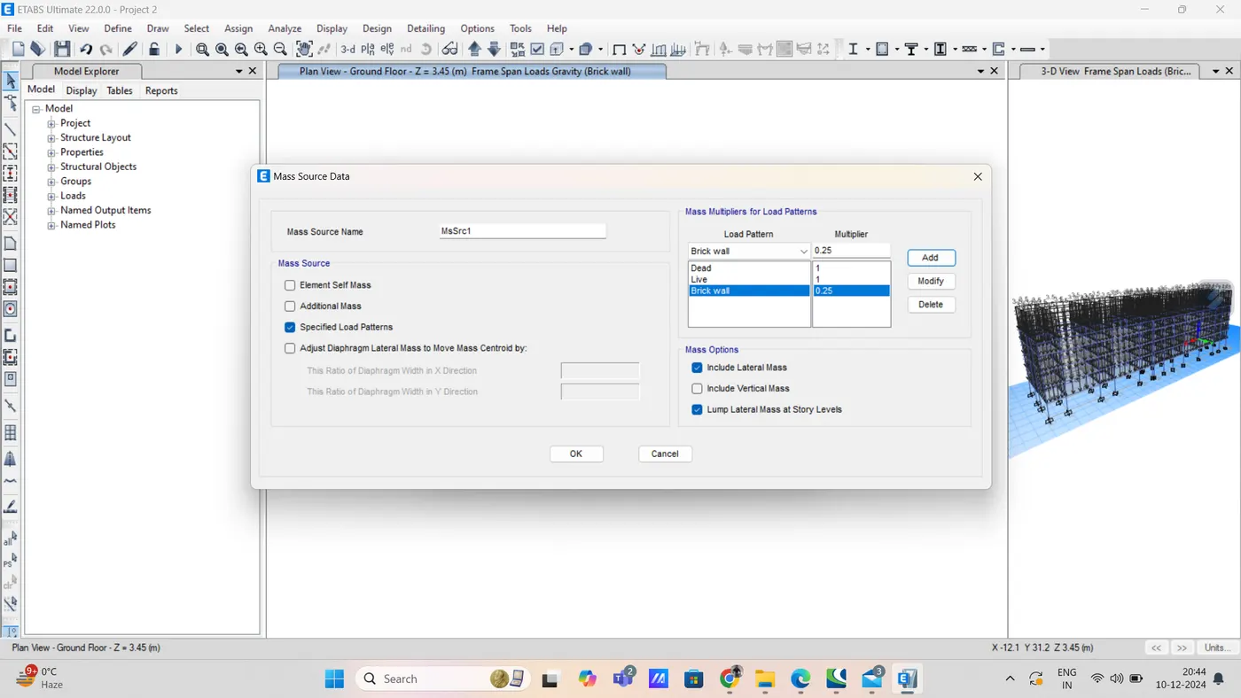
in that add load pattern in mass source data
like that
step 14) load combination
select load combination from define option
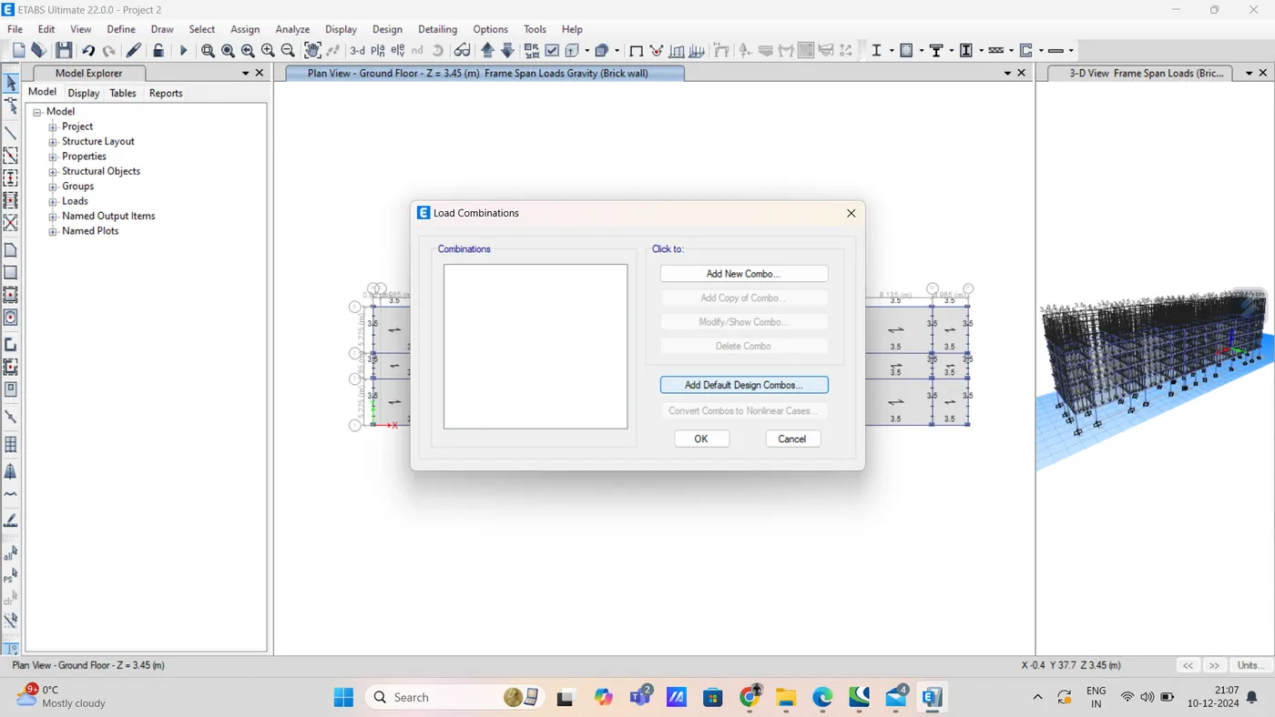
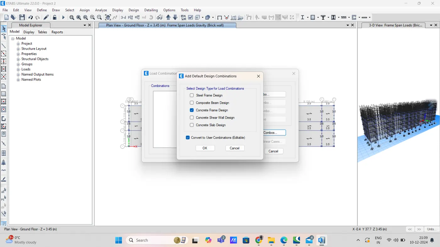
in that click on add default design combos
in that click on concrete frame design
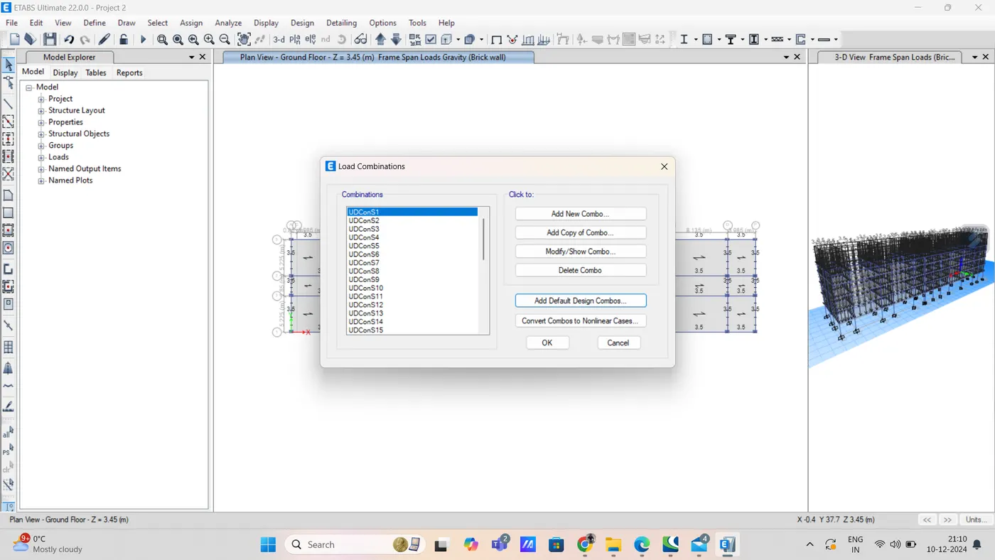
step 15) select floor for diaphragm
select option then object type then floor
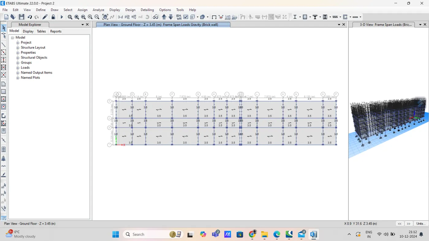
then select diaphragm from shell option from assign
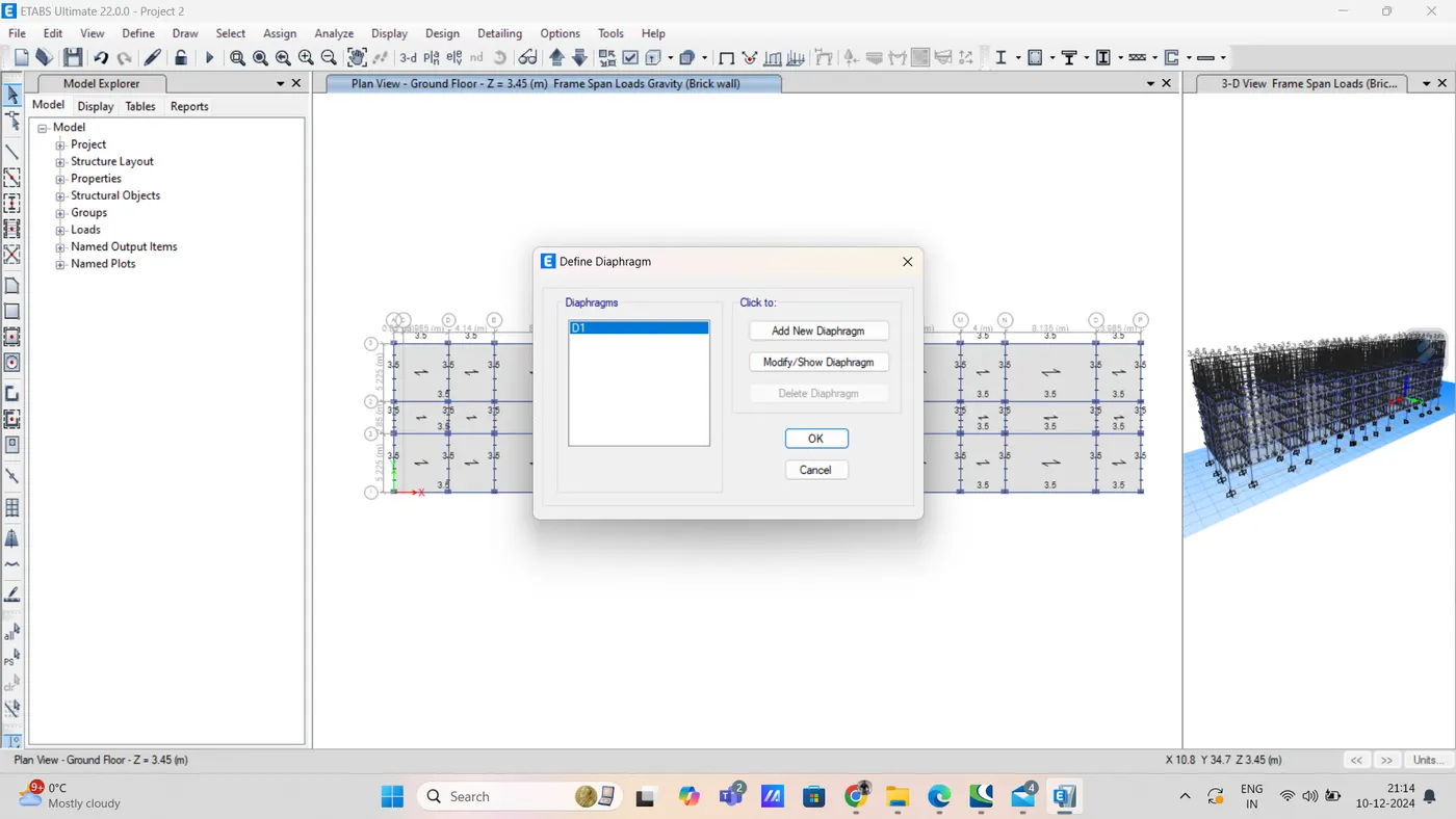
then click on D1 press apply and then close
diaphragm is assigned to slab
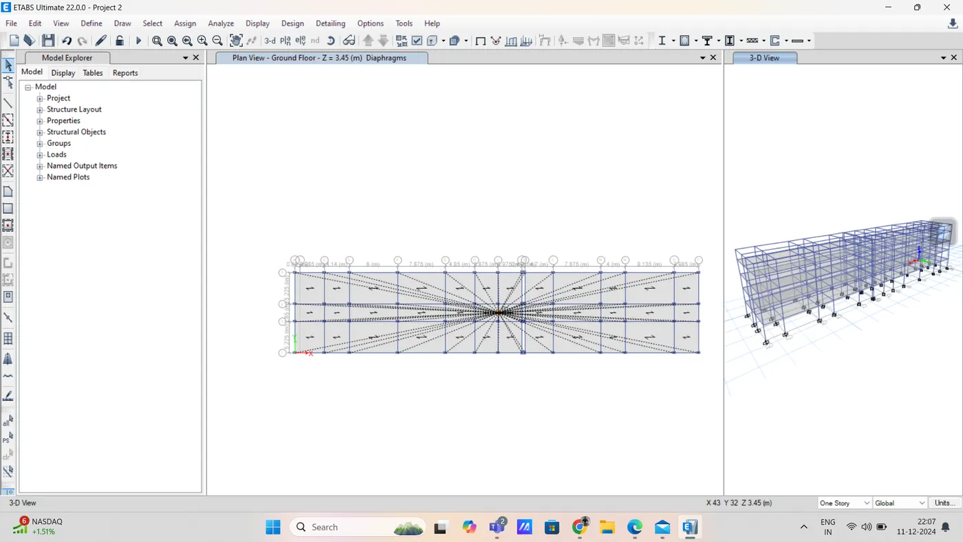
Step 16) Run analysis
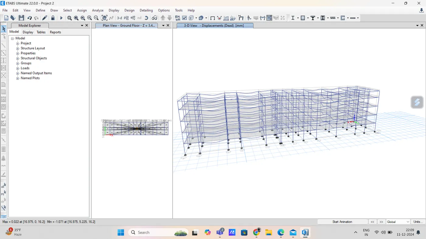
Step 17) now beam design and column design by selecting start design option
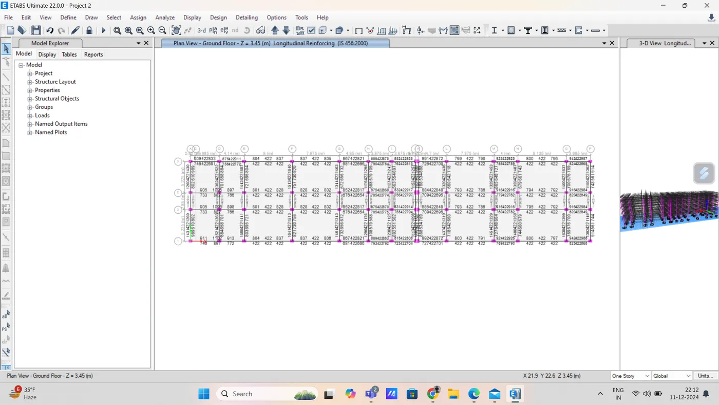
after that we select display design information from design option
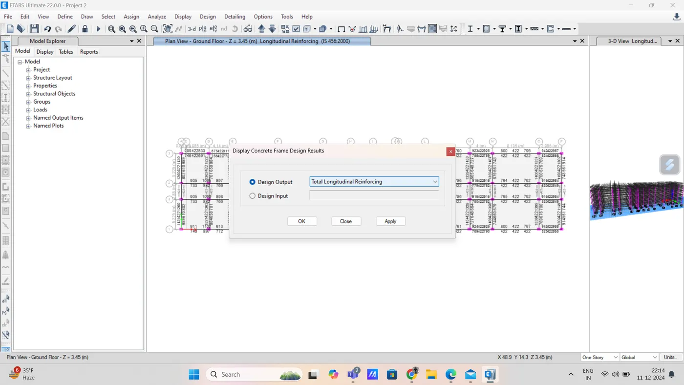
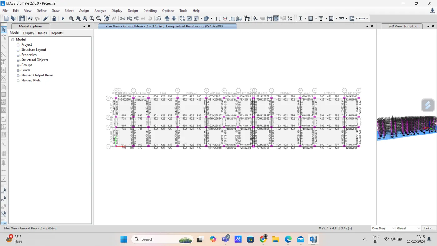
also check for shear reinforcement
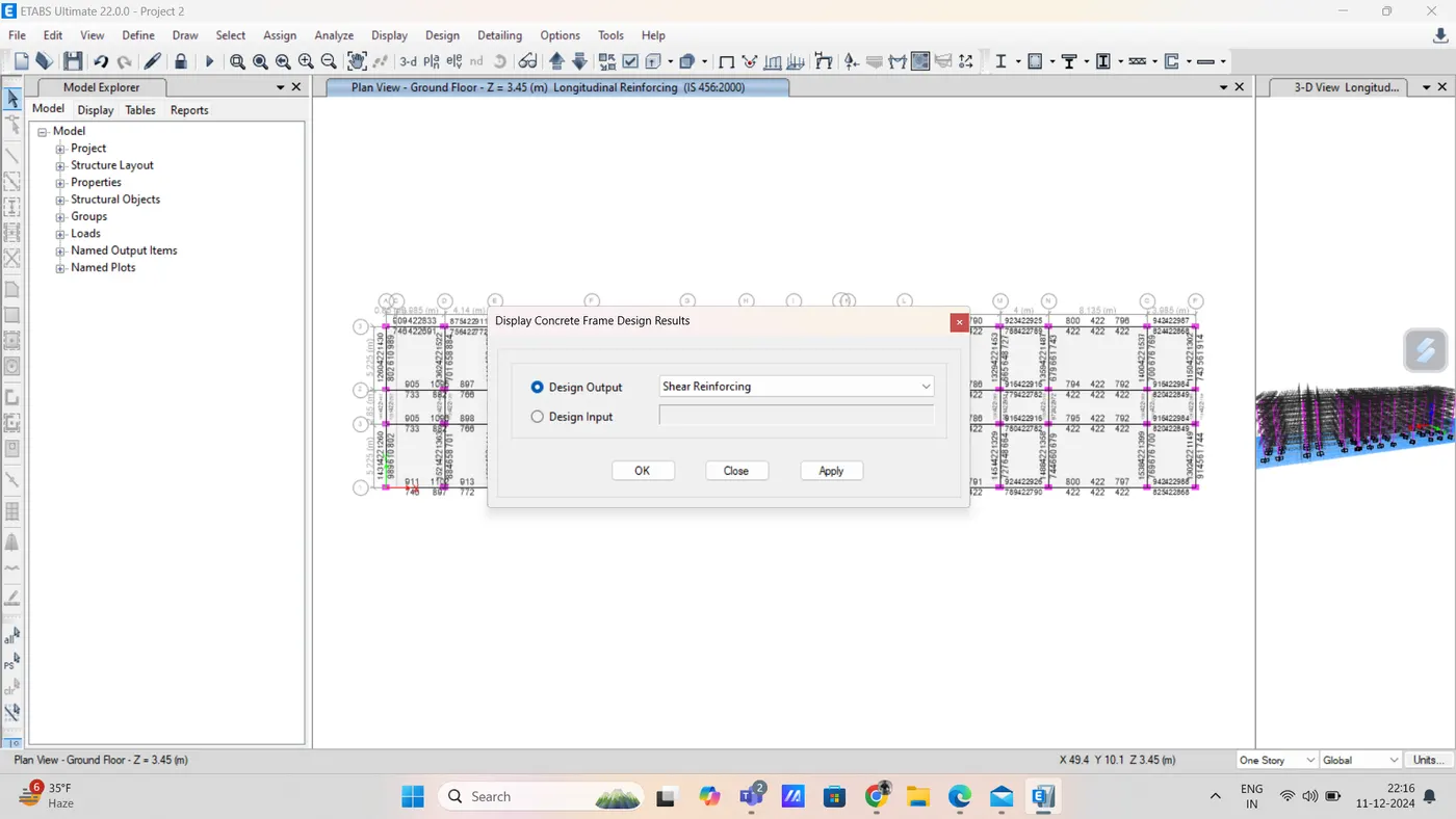
and for column we need 2340 sq.mm reinforcement required
step 18) export base floor load and load from above in safe
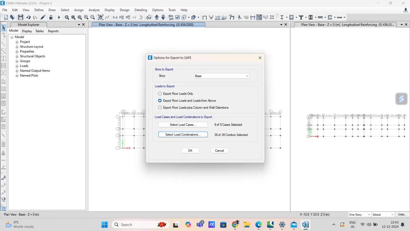
SAFE model (foundation Design)
step 1) after exporting etabs model to safe then open the safe and import file
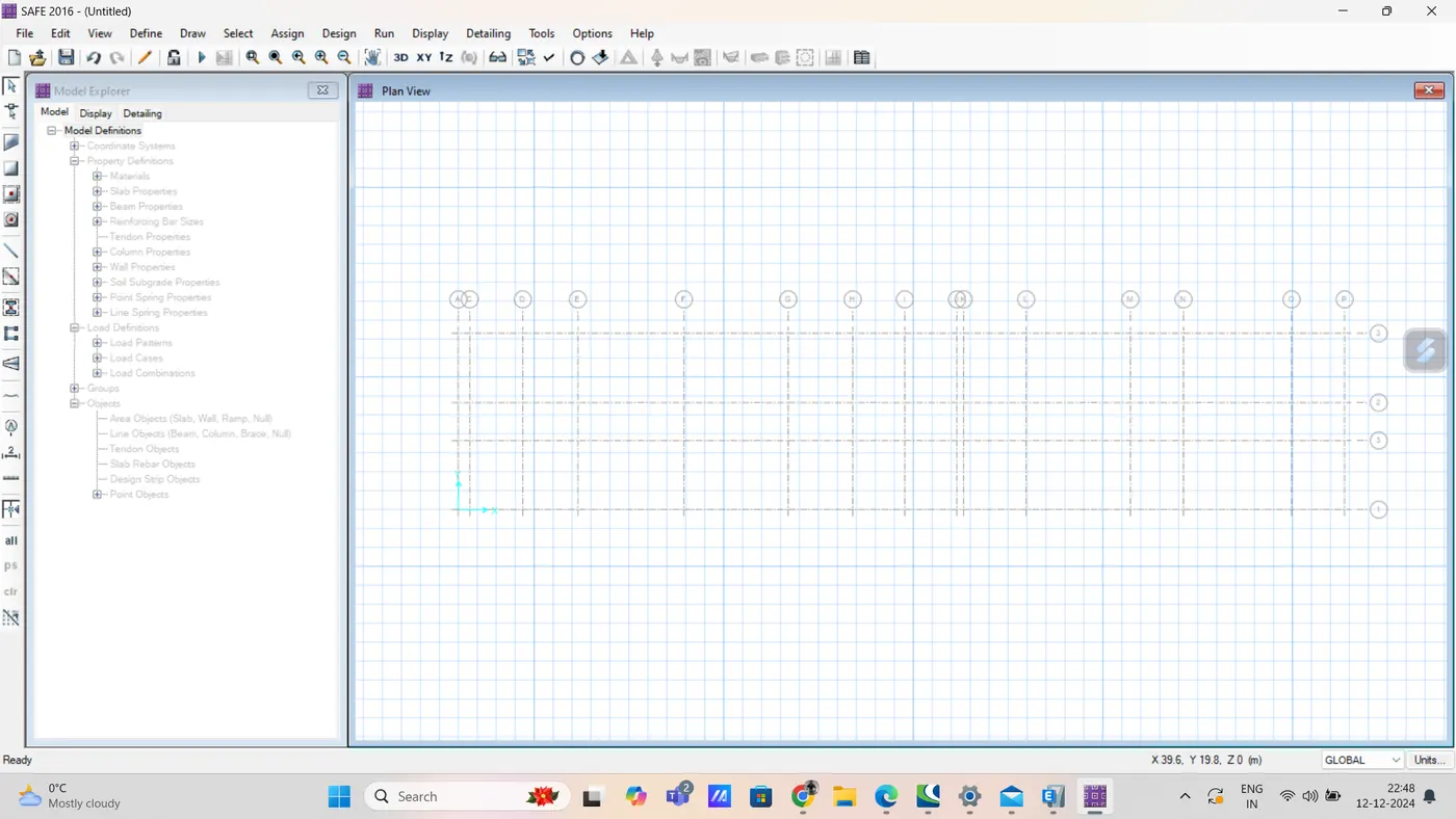
step 2) now show load from display option
dead above load
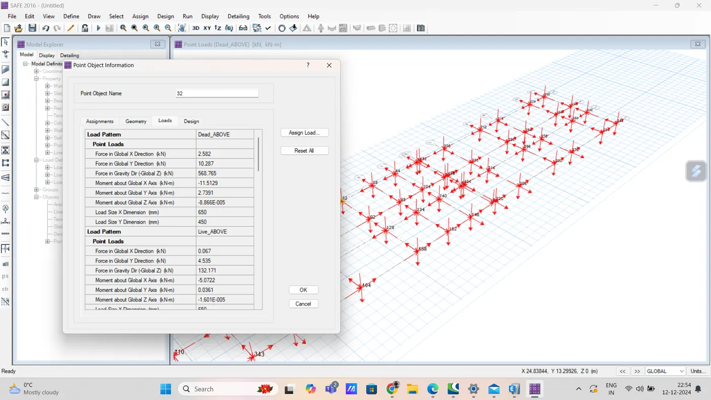
Step 3) given in question
soil type = 3
piles of length = 10m
pile dia = 500mm
load carrying capacity = 280KN
pile cap = slab type = mat = 500mm thick
column cap slab = stiff 500mm thick
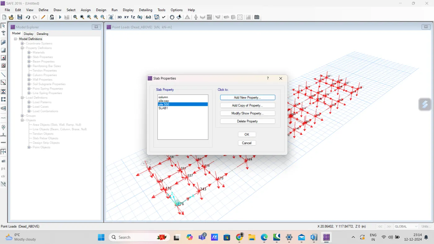
so firstly, define the slab property
Step 4) define slab property
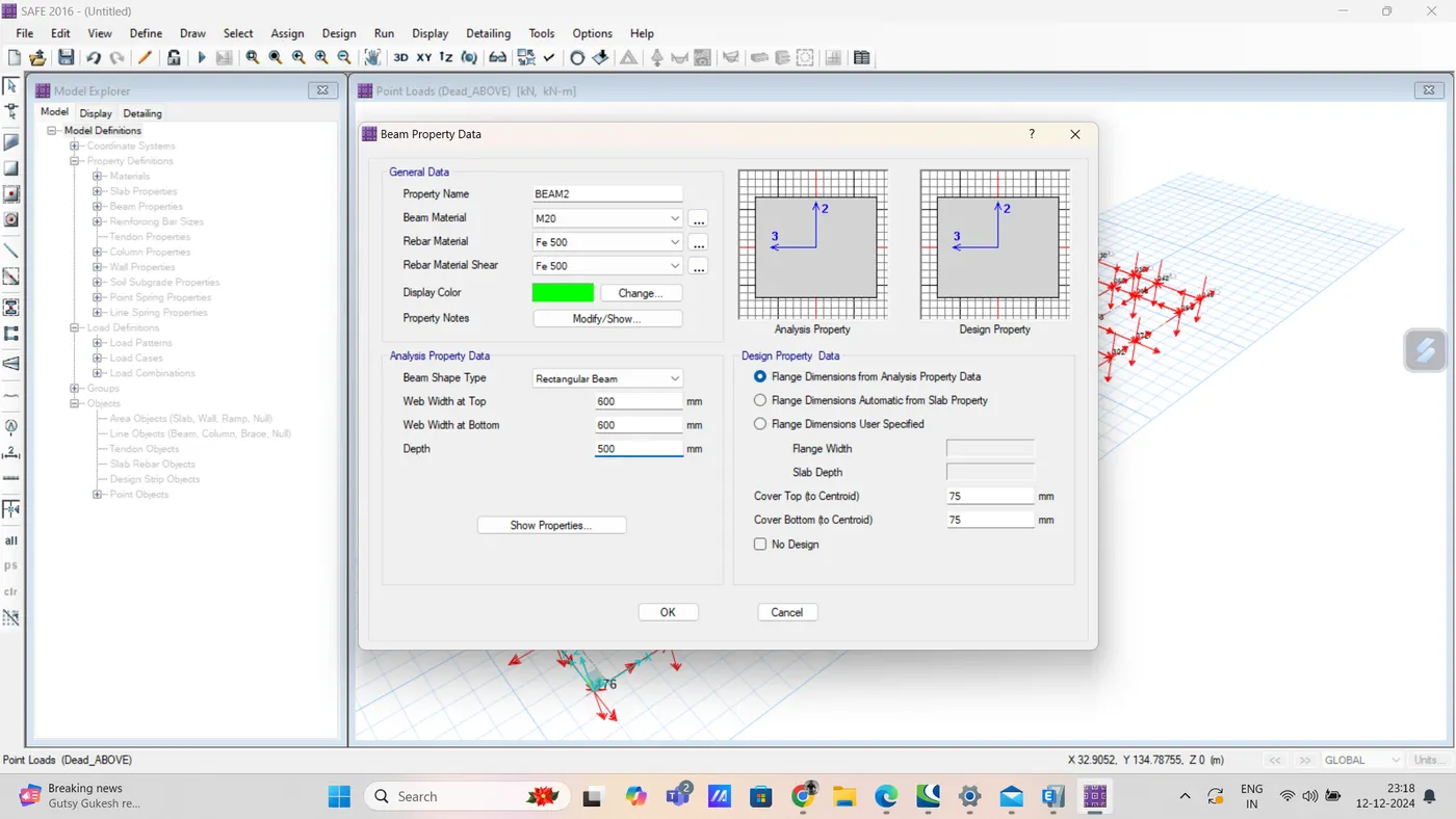
step 5) RC beam section of tie connection of foundation is 600X500mm is assigned
step 6) for piles the point springs are assigned
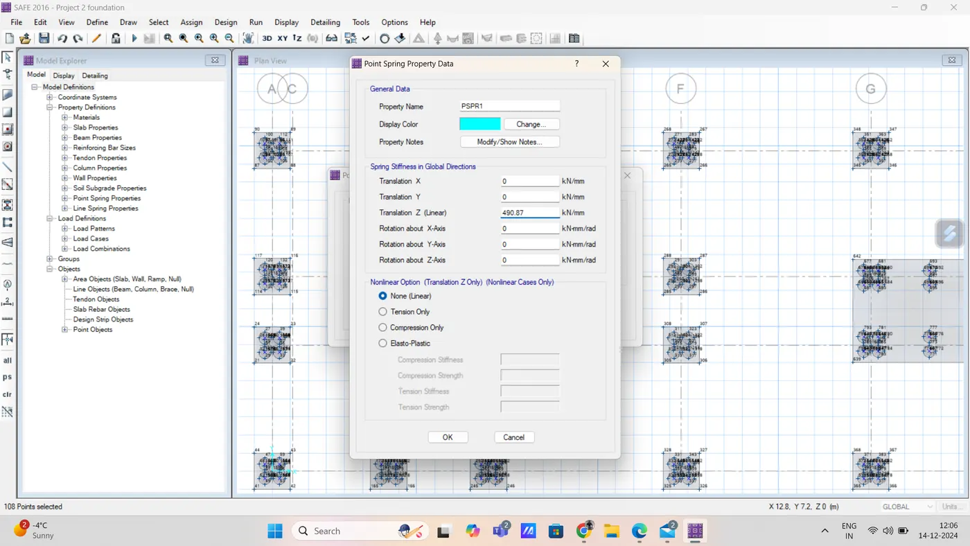
step 7) for bearing pressure checking the service load combination is considered
for flexural design the ultimate load combination is considered
Step 8) Define the soil
step 9) Draw the points for the reference of the pile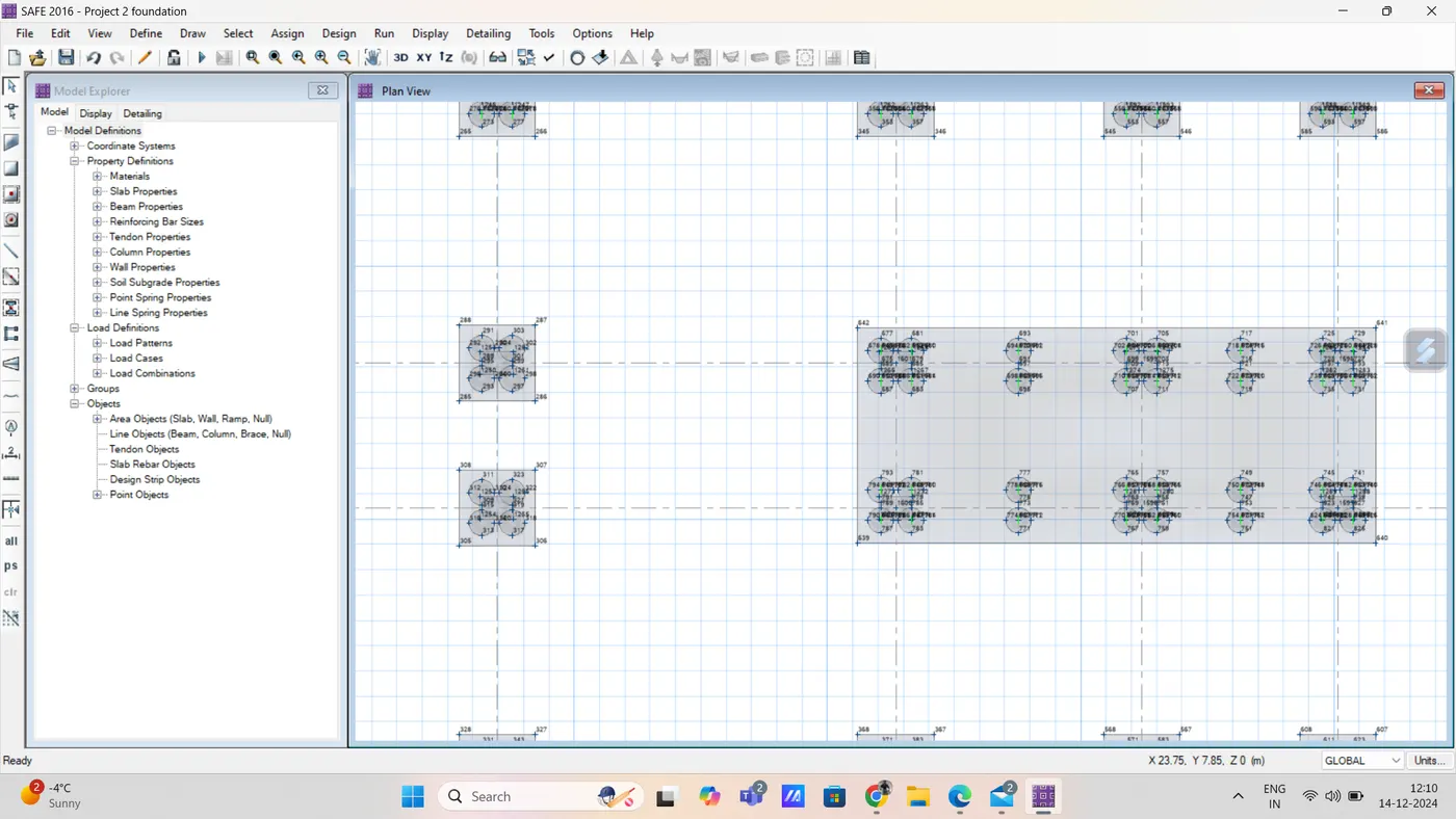
Step 10) draw piles And assign the point springs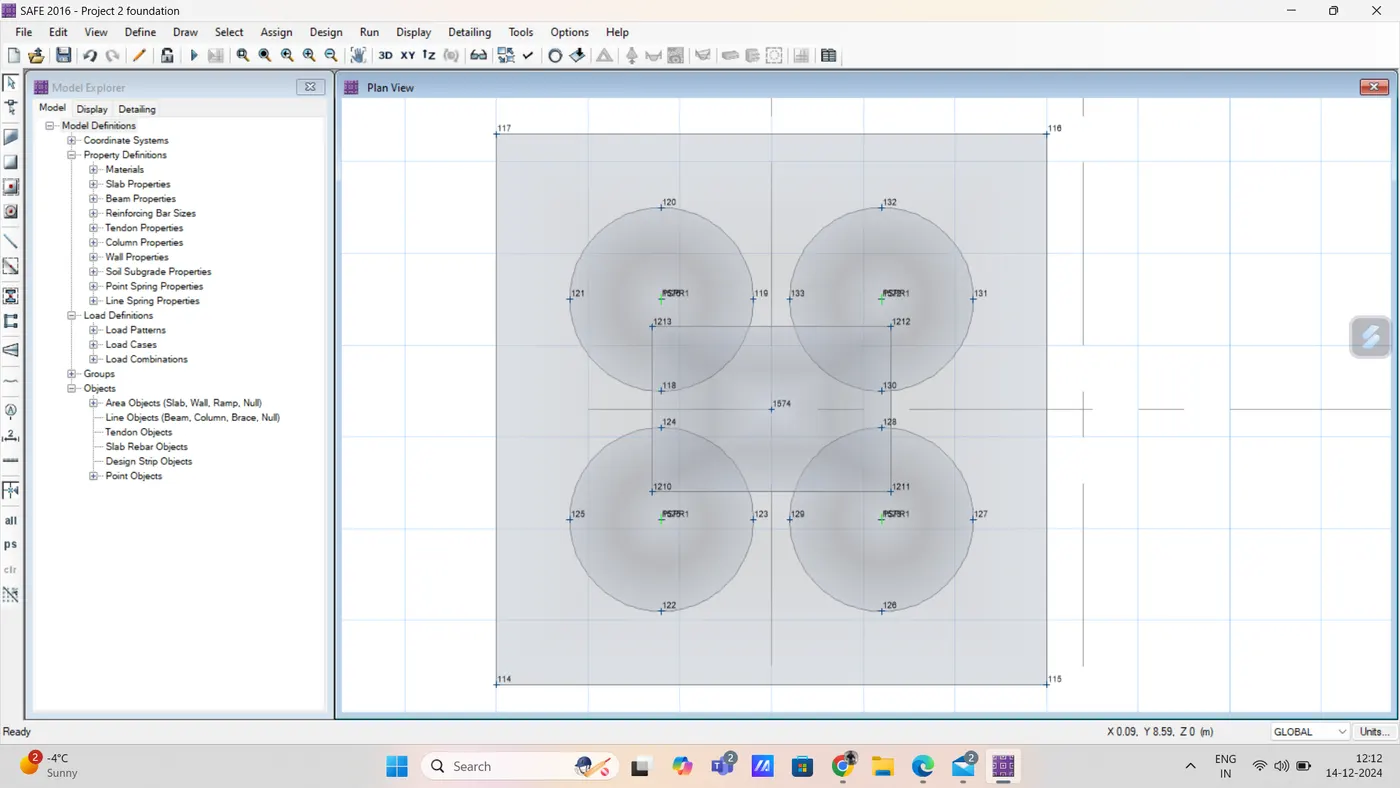
step 11) Draw columns below the loads
.
step 12) Run model Display the deflection
.
Step 13) Reactions
.
Step 14) Punching shear
Step 15) Design reinforcement
Since load was heavy the model divided to 3 pasts and analysis was done
.
.
.
.
Result:
G+3 Hostel building design and analyse is done in etabs &
the foundation design and analysis in safe also done