Project 2_Design & Analysis of a Hostel building at Guwahati, Assam
In this project, participants will get to experience the entire design process from modelling, analysis, design, and preparation of construction drawings. The architectural drawings of a G+3 RCC building is provided. The following information on the building is to be used:
- Location – Guwahati, Assam
- Function – Hostel block in an academic institute
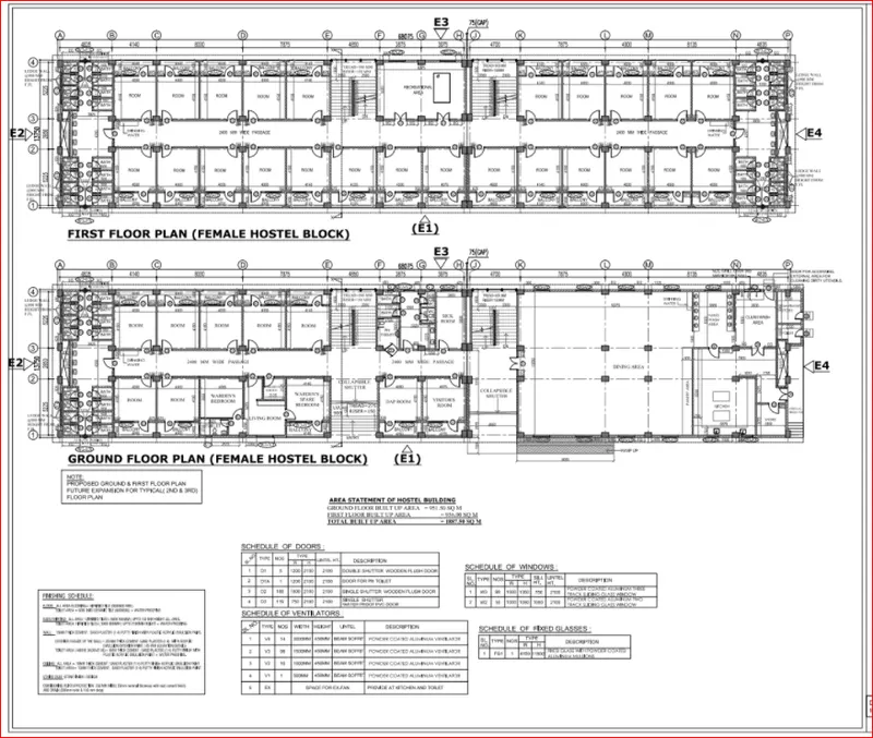
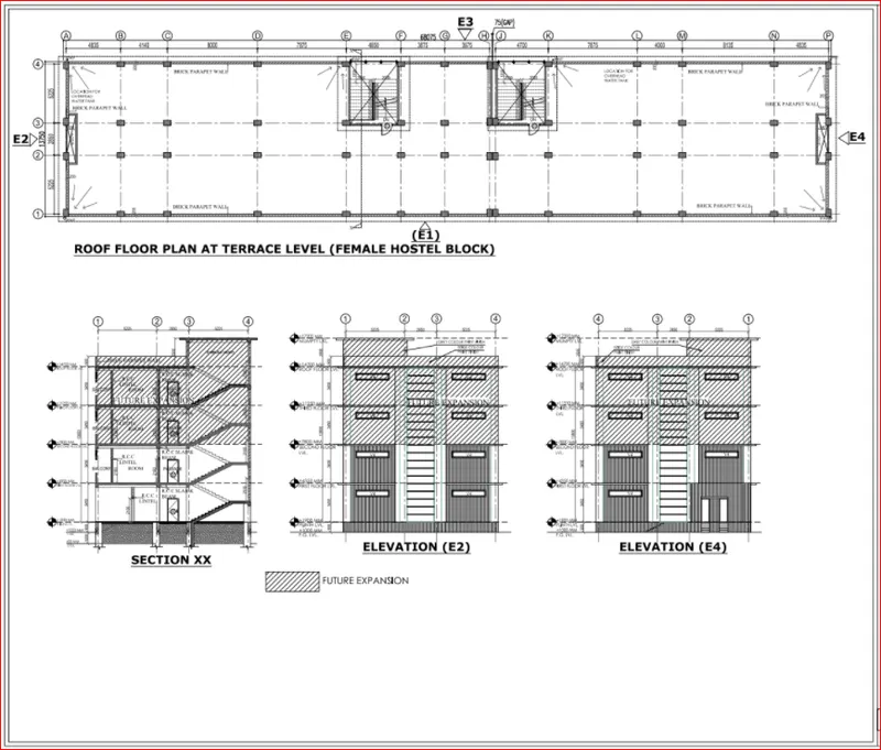
The walls will be made of AAC blocks. Other loadings are to be calculated as per the architectural drawings.
The buildings rests on type 3 soil. Piles of length 10 meters and 500 mm diameter with a load-carrying capacity of 280 KN is to be used.
The ground floor level will be at a height of 2 meters above the existing site level to avoid floodwater enter the building.
M25 grade of concrete with Fe500 for longitudinal reinforcement and Fe 415 for shear reinforcement is to be used.
Aim - To design and analysis of G+3 Hostel building in ETABS and Foundation in SAFE.
Introduction -
The procedure for nalysis and design for given building will depend on the type of building, its complexity , the number of stories etc.
First the Architectural drawing of the building are studied, structural systemis finalized sizes of structural members are decided and brought
to knowledge of the concerned architect.
The procedure for structural design will involve some steps which will depend on the type of building and also its complexity and the time
available for structural design.
Procedure -
Step 1.
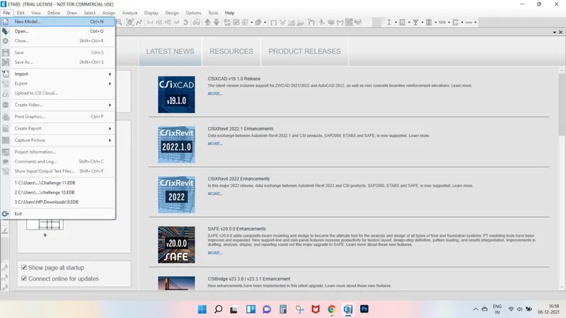
First we have open the Etabs software.
Next click on the file option at the left side top corner and select the new model.
After selecting the new model the new tab opens, in that tab we have to select Use built in setting with option.
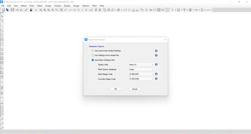
After selecting the model initialization templates tab will opens and select the grids only and press ok.
Next we need to do the setting in grid system data.
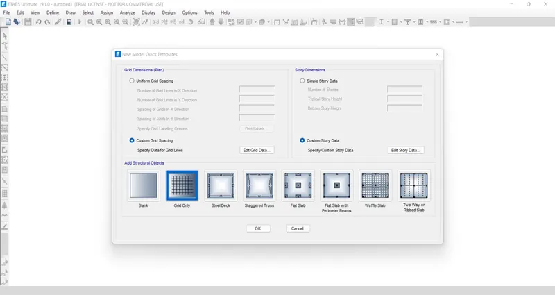
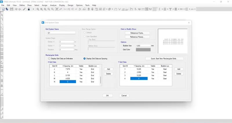
Next we need to add the stories upto 3 storey in the storey data.
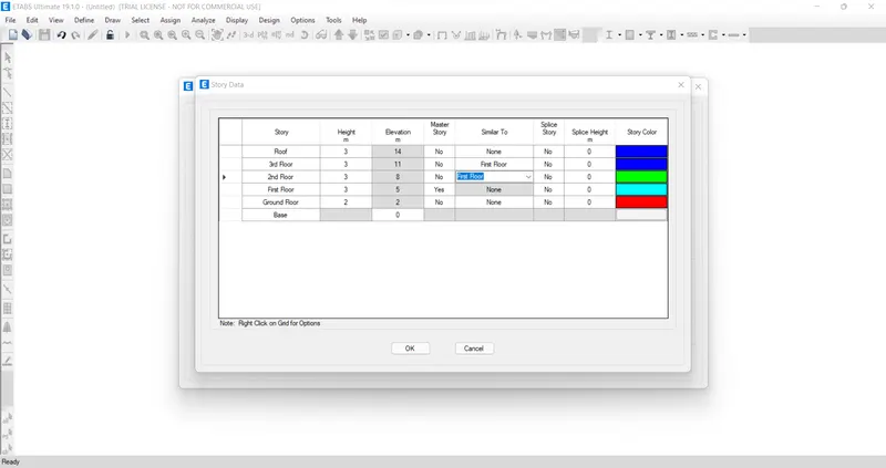
Steps 2.
Next the plan views are visble in the screen.
Next we need to open the 3D view.
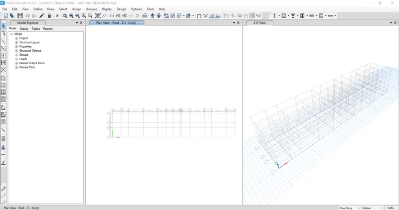
Step 3.
Next we need to select define option and select material properties.
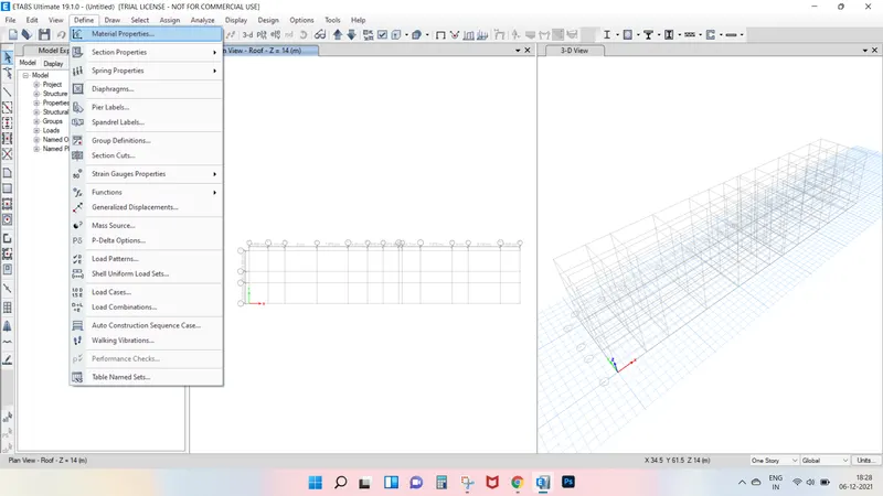
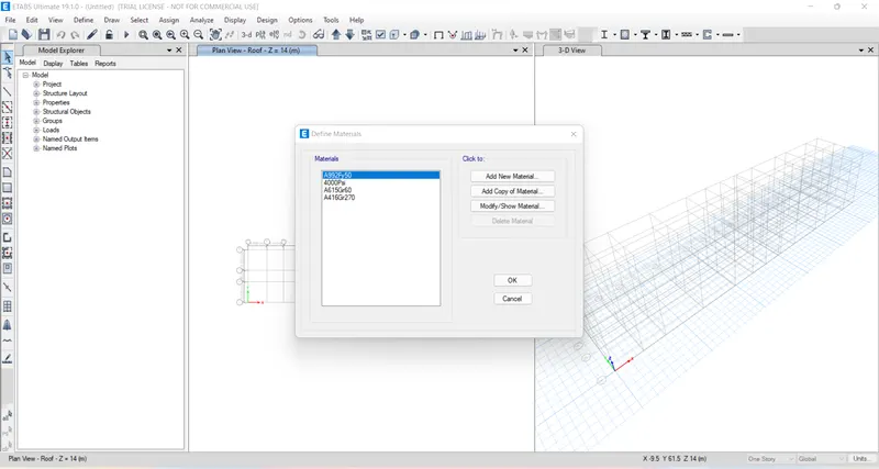
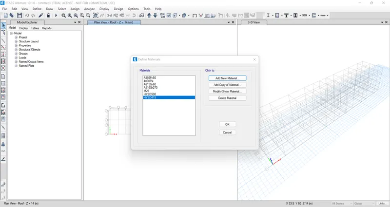
After selecting the material properties the new tab appears then we add new materials by selecting the add new material option.
Step 4.
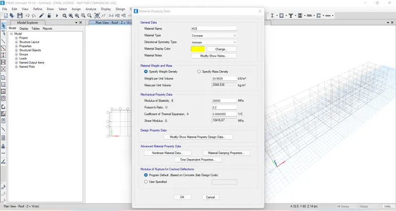
Now we need to add material type as concerte and grade as M25.
Next we need to check the material propety data.
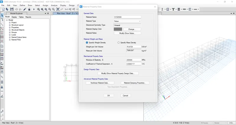
Now we need to add new material type as rebar and grade as HYSD grade 500.
Next we need to check the material property data.
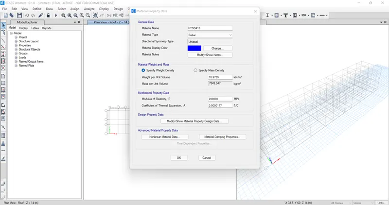
Now we need to add new material type as rebar and grade as HYSD grade 415.
Next we need to check the material property data.
Step 5.
Now we select the section properties and click on the frame section.
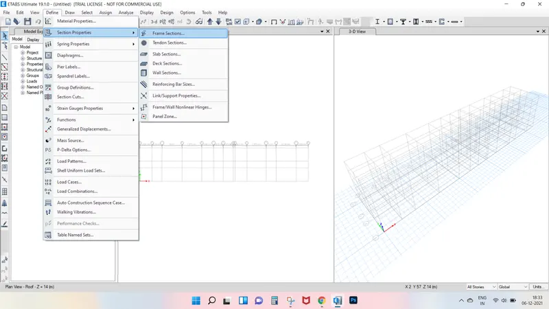
After selecting the frame section the new tab will be visible, in that we need to select the Add new property.
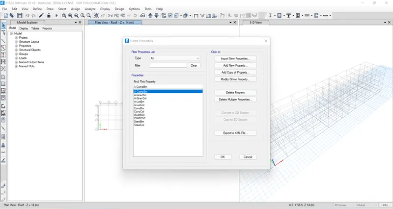
After selecting the Add new property the new tab appears.
In that new tab we select the rectangular shape type in concrete.
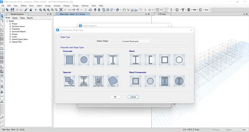
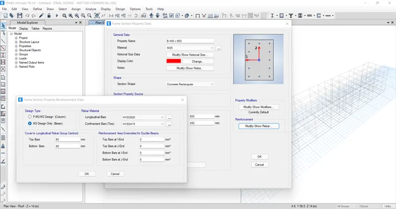
Next the frame section property data will be visible, in that we add beam size as B450 x 650.
Next we need to select the Modify/Show Rebar option .
After selelcting the Modify/Show rebar option the new tab appears, in that we select the design type as M3 design only.
Next we select the Longitudinal bars with grade of HYSD 500.
Next we select the Confinment bars with grade of HYSD 415.
Step 6.
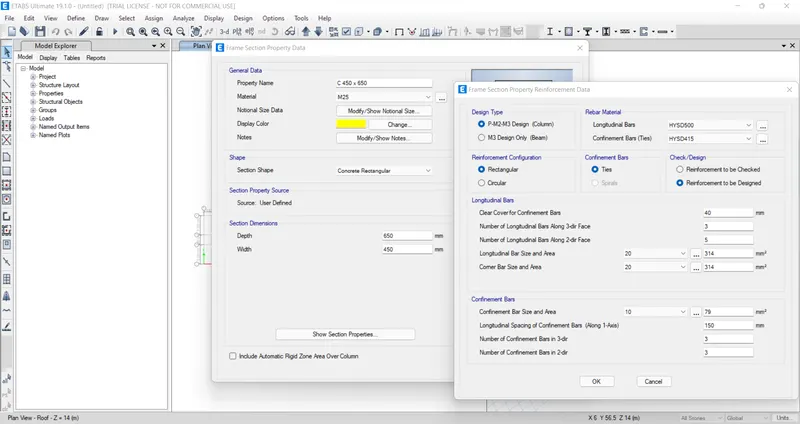
Next we have to add column size as 450 x 650 in the frame section property.
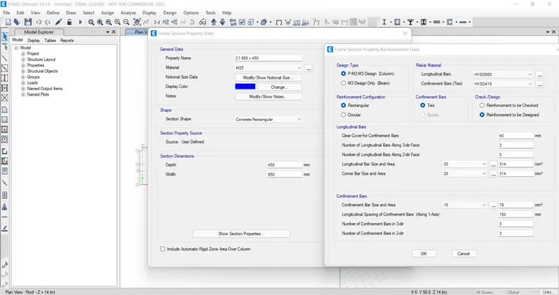
Again we have yo add the another column size as 650 x 450 in the frame section property.
Step 7.
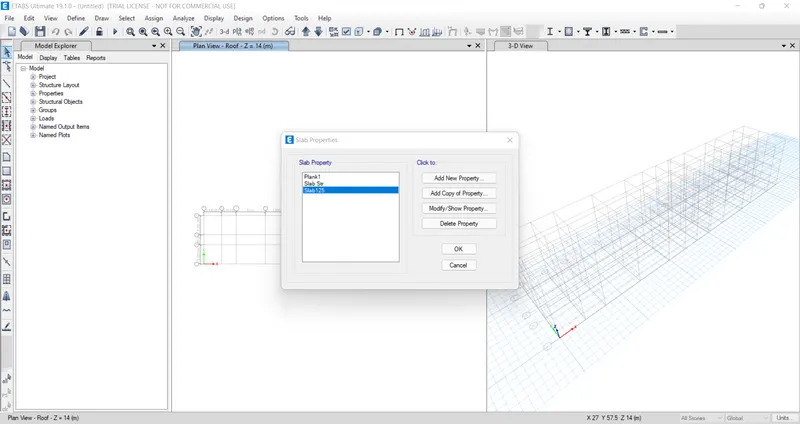
Next we select the slab section option from the section property.
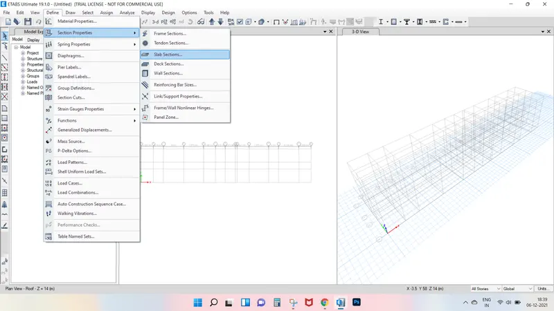
Next the slab properties tab will be visible, in that we select the modify/show property option.
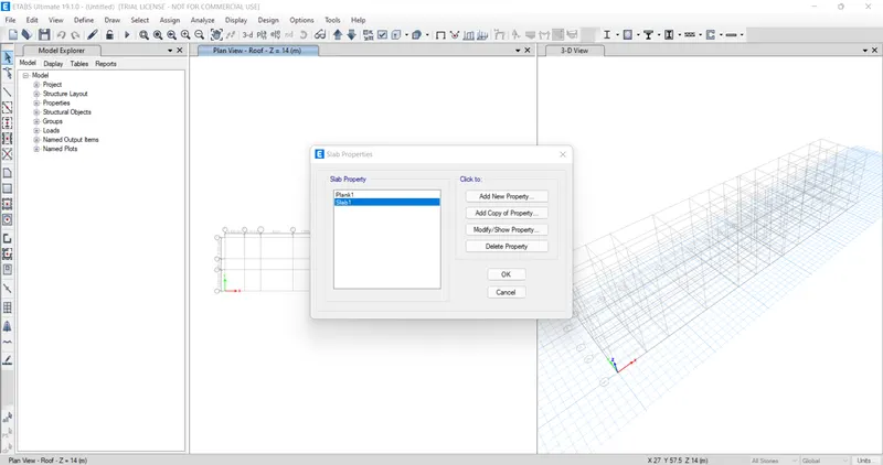
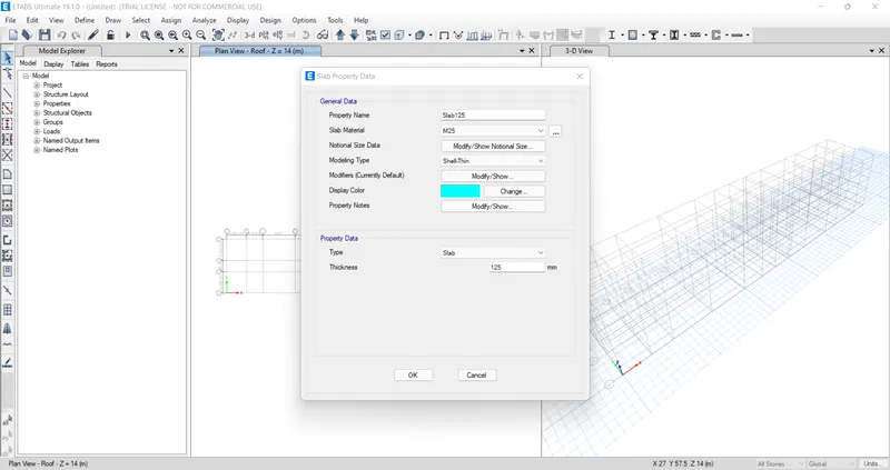
After selecting modify/show property option,the new tab appears.
In that we need to put the slab name as slab 125, it means slab with the thickness of 125 mm.
And we take the concrete grade as M25.
Next we have to click the ok option.
Now we take slab thickness seperately for staircase with the thickness of 200 mm.
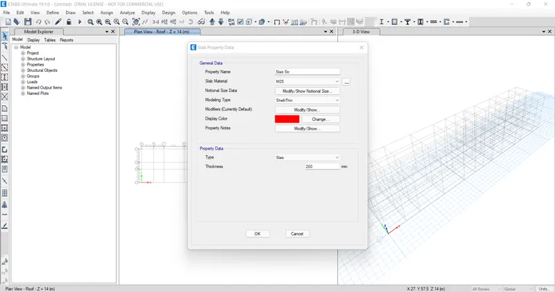
Hence, the slab proeprties are assigned.
Step 8.
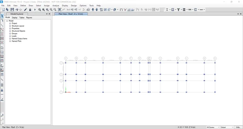
Next we need to add the columns using the quick draw columns option.
Step 9.
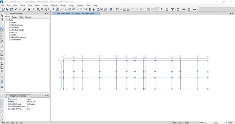
Next we need to add beams using the quick draw beams option.
Step 10.
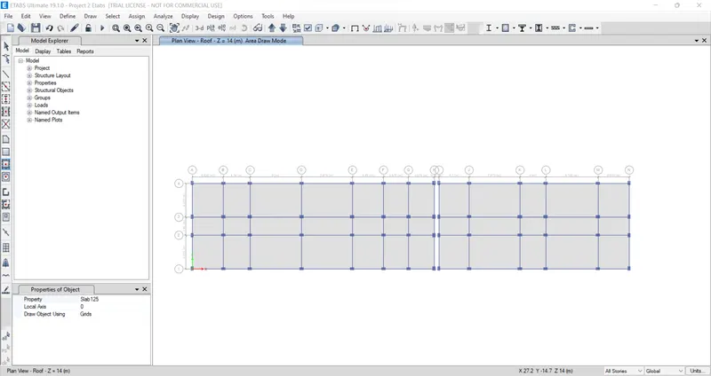
Next we need to add the slab using the quick draw floor/ wall option.
Step 11.
Now we go to the base plan and select all base points.
Next we select the restraints from joint option.
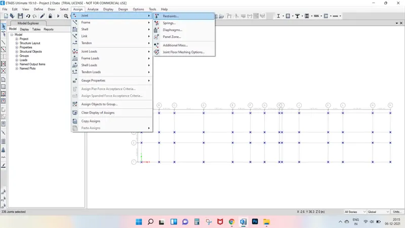
Now we need to select the fixed joint and click on apply and then click on close button.
Step 12.
Next we need to select the load patternes from the define option.
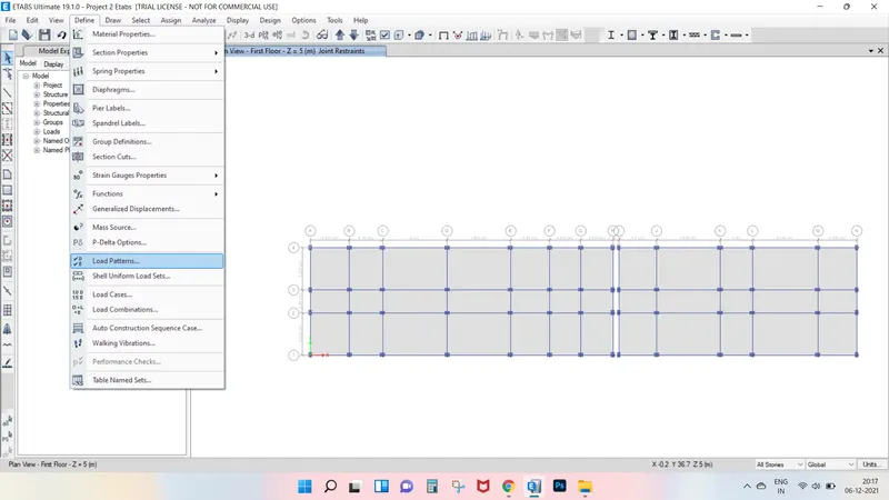
Now we should add dead load, live load, Brickwall load and earthquake load.
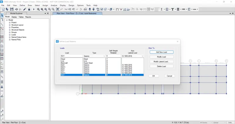
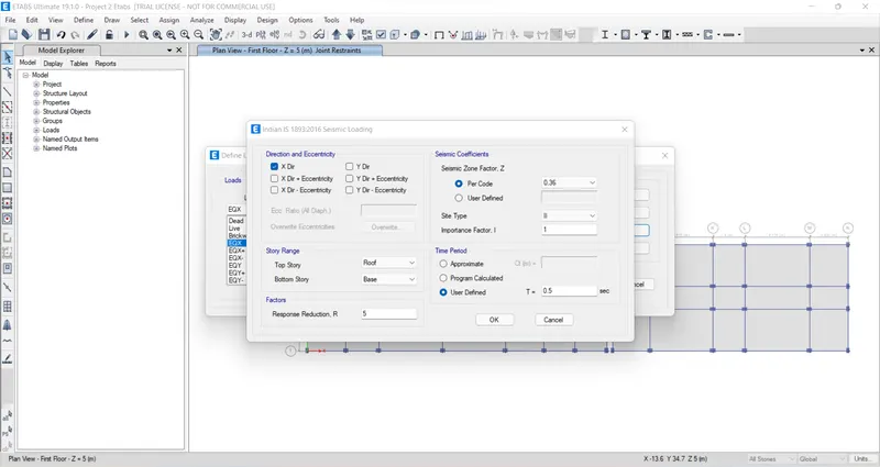
Next we need to select eqx and click on the modify lateral load, then the new tab appears.
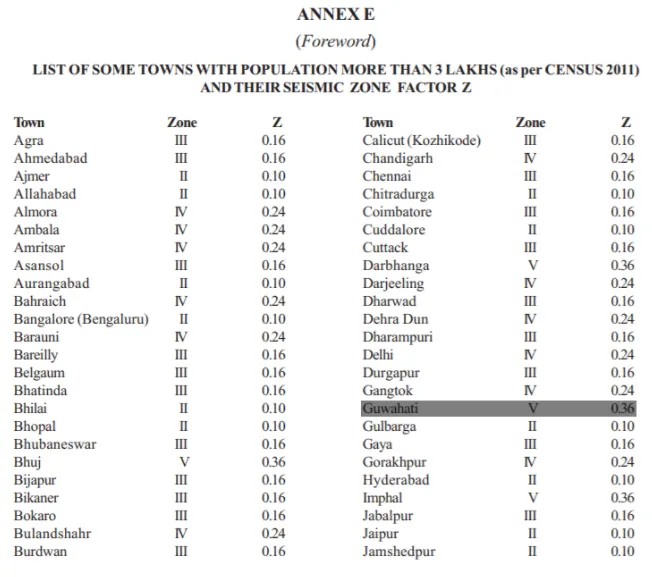
In this tab select X dir and as per IS 1893;2002, the seismic zone factor for Guhawati , aassam is taken as 0.36 as mentioned on the below table.
And we need to select site type as lll.
Next click on the ok button.
Similarly, do this for all the seismic loads such as eqx+, eqx-, eqy+, eqy-.
Step 13.
Now we select the object type option.
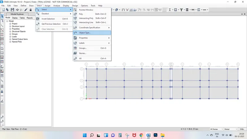
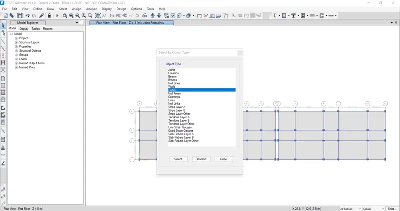
After selecting the obejct type option, the new tab will be visible, in that select the floors and click on the select button and close.
Next we have to click on the assign option and then select shell loads, from the shell loads we select the Uniform option.
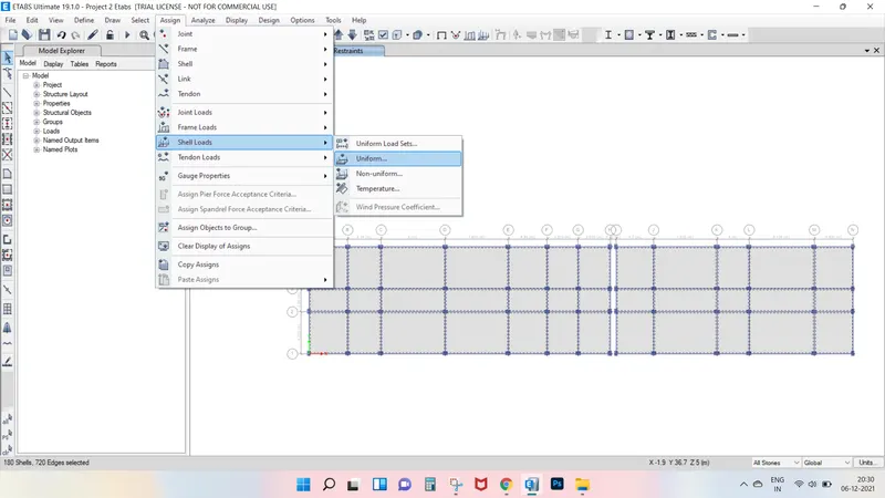
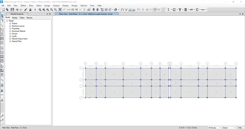
Here we need to consider the live load upto the 3rd floor with 2 kn/m^2.
Step 14.
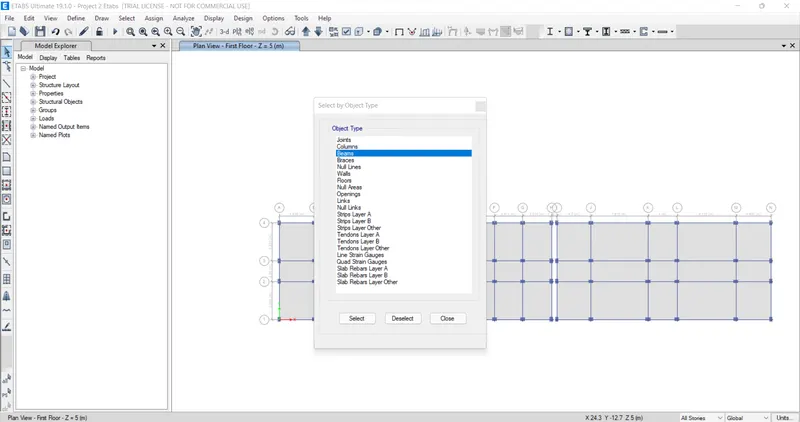
Next we select the object type option.
After selecting the obejct type option, the new tab will be visble, in that select the beams and click on the select button and close.
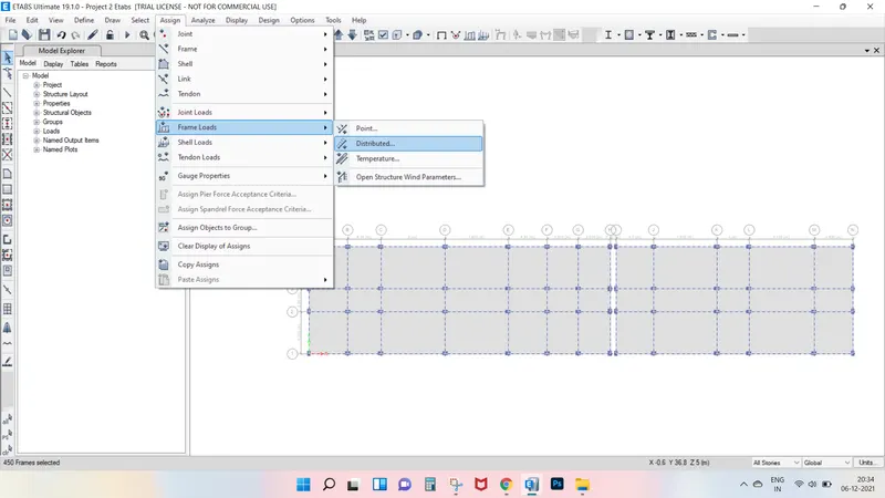
Next we have to click on the assign option and then select frame loads, from the frame loads we select the distrubuted option.
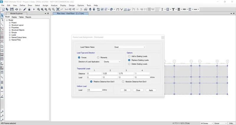
Then after the new tab will appear, In that we select pattern as brickwall and take the uniform load as 3.5 kn/m, and then click on the apply button and close.
Now we click on the toogle option to view the loads acting on the storey.
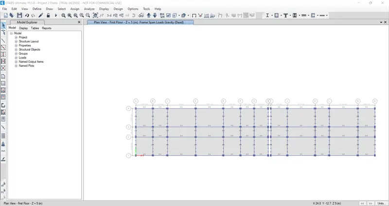
Steps 15.
Next from the define option we select the mass source.
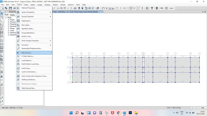
In the mass sorce tab, we select modify show mass source opton.
Next we add the load patterns in the mass source data.

Step 16.
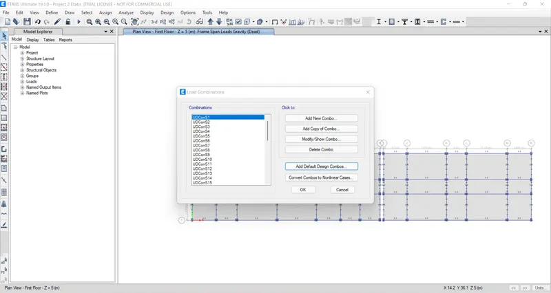
Next from the define option we select the load combinations.
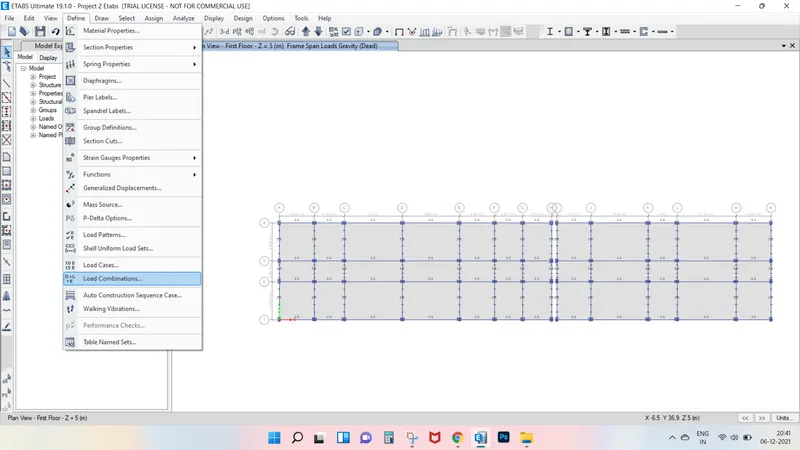
After selecting the load combinations the new tab is visible, in that we select Add Default Design Combos option.
Next we select concrete frame design in the Add Default Design Combinations.
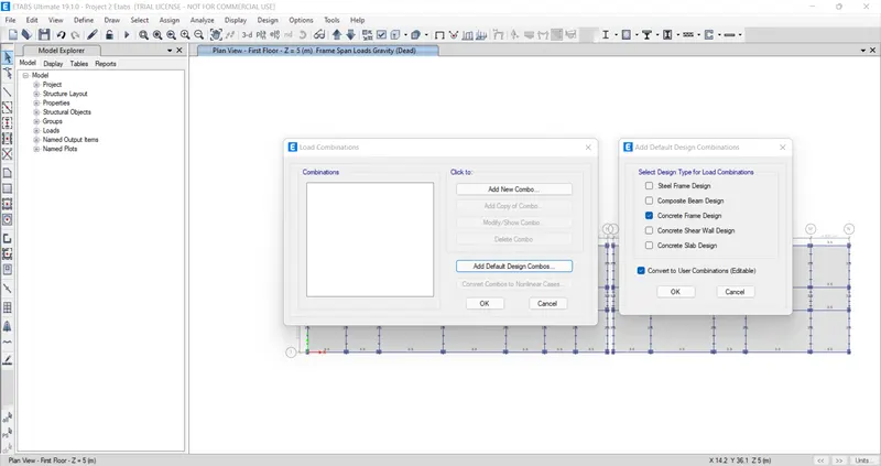
Now we can see here that the load combinations are visible.
Step 17.
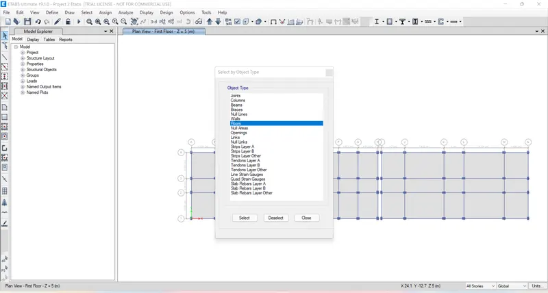
From the select option we select object type option.
After selecting the object type option, the new tab will be visible, in that select the floors and click on the select button and close.
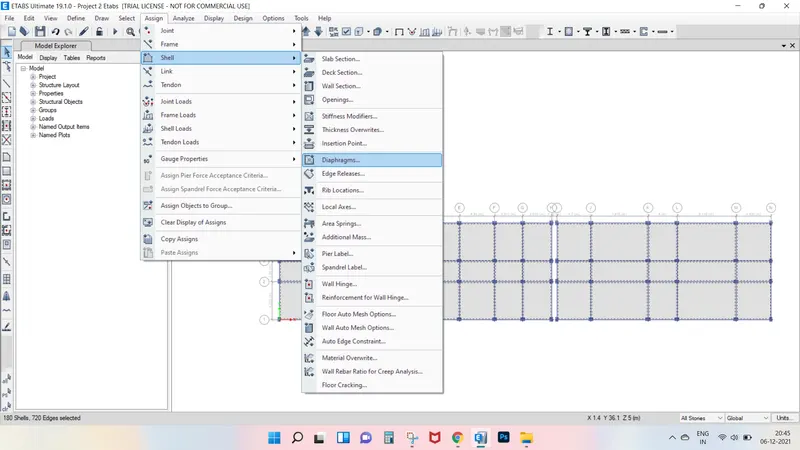
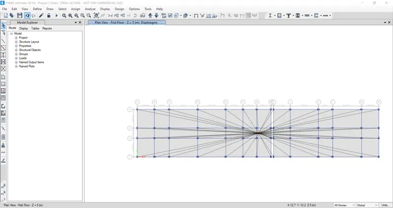
Next we have to select the Diaphagrams from the shell option.
After selecting the diaphagrams the new tab will appear, In that select D1 and click on the apply button and close.
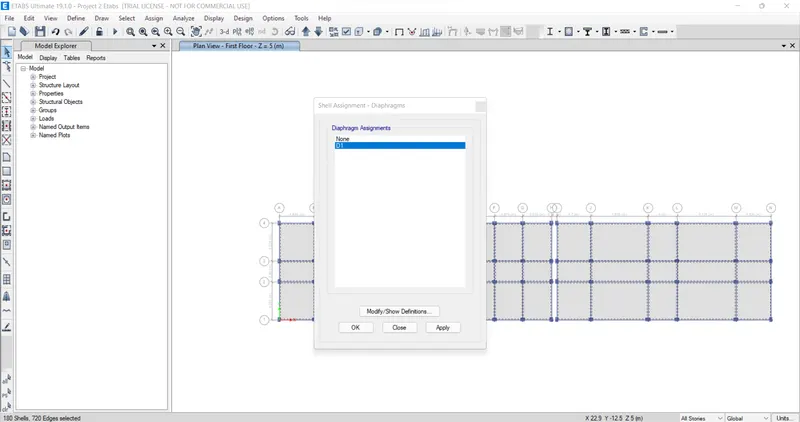
Hence the diaphagrams are assigned.
Step 18.
Next from the define option we select the modal Cases.
After selecting the Modal cases the new tab is visible, In that we give modal case name as Modal 1 and we give the maximum numbers of mode as 20.
Step 19.
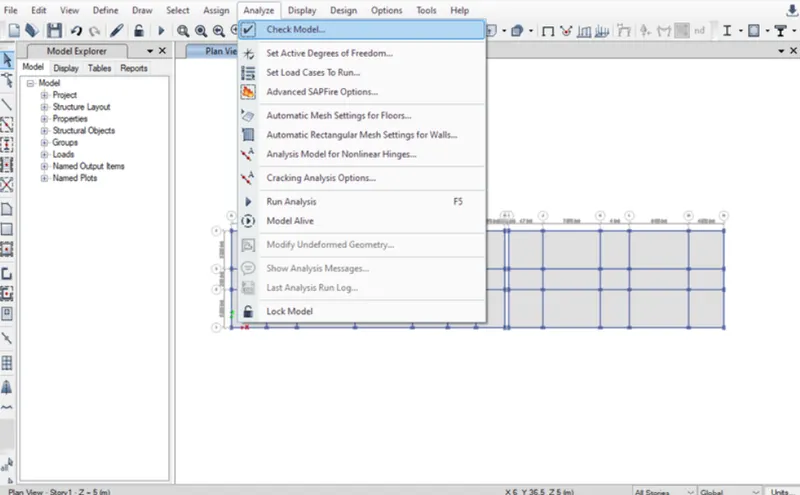
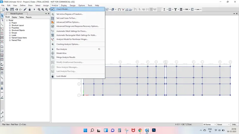
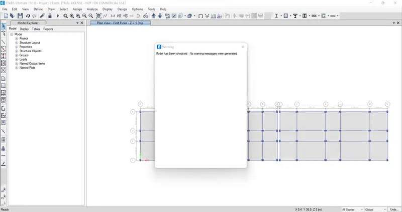
Next we have to check the model by clicking the check modal option.
Next the check the modal tab will appears, in that selct the all options and click on the OK button.
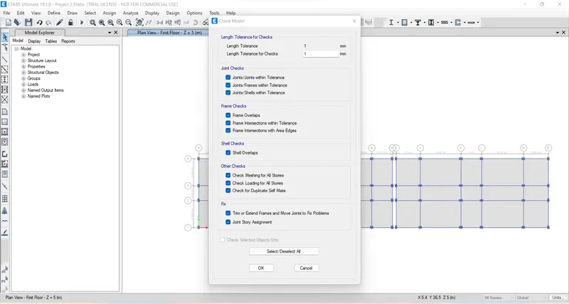
After the modal is checked, then the warning tab will be visible and it tells that there is no warning message.
Step 20.
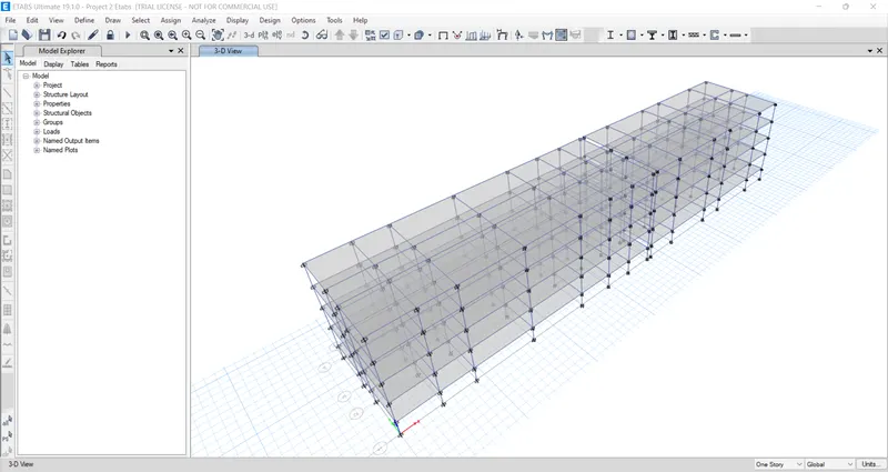
Now we have to do the run analysis.
Step 21.
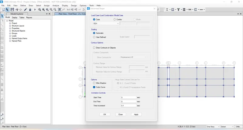
After Run Analysis we select the show deformed shape option the new tab appears.
In the deformed shape tab, we select the earthquake load in the load case.
Next we see the deformed shape of the structure with earthquake load.
Similarly, we have to do this for all the remaining loads.
Step 22.
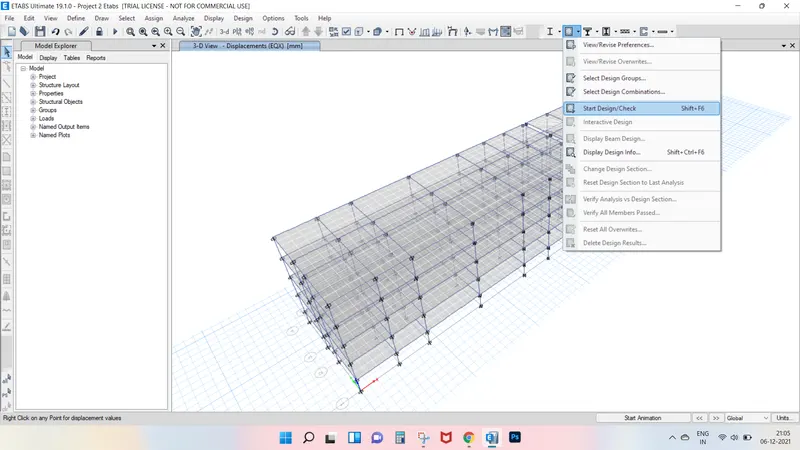
Next we have to start the beam design and column design by selecting the start design check option.
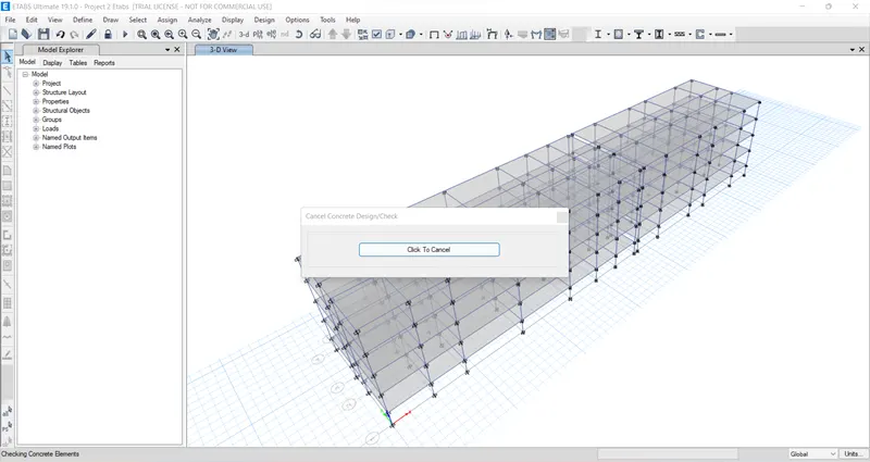
Step 23.
After complition of the beam design and column design, we need to select the Display design info option.
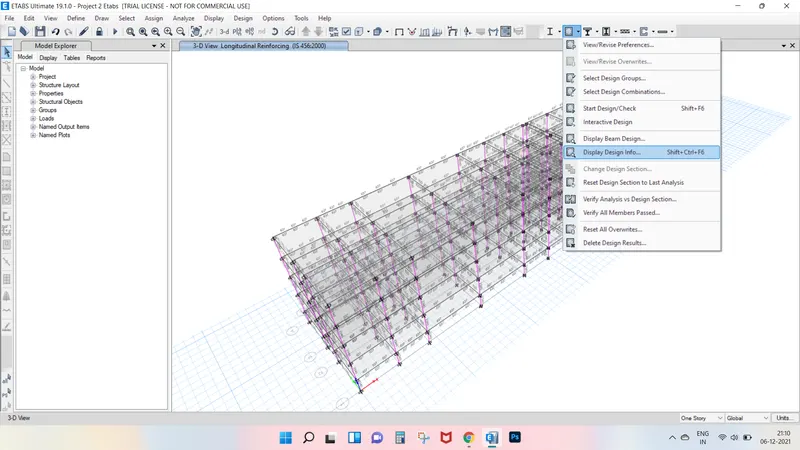
After selecting the Display design info option the new tab appears, in that we select the Longitudinal reinforcing in the design output
and click on the Ok button.
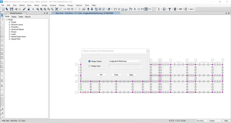
Next longitudinal reinforcement will appear
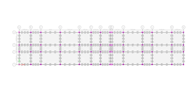
Next we draw the Reinforcement diagram of 7 span continuous beam along grid 1 and also need to provide the reinforcement details.
The maximum Ast for the bottom support is 637 mm^2 and bottom middle is 637 mm^2.
The maximum Ast for the Top support is 1038 mm^2 and Top middle is 1038 mm^2.
Now we provide 6-12 at the top and bottom.
Next we provide 3-16 at the top support for the continuous beam.
Step 24.
Now, here we can see that the details of column reinforcement.
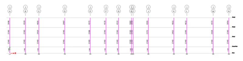
Now we take column 1L for reinforcement, now take the column size as 650 x 450 mm.
The maximum Ast for the column is 4632 mm^2.
Now we provide 16 bars with 16 mm dia .
And we provide size of the stirrups as 10 mm for zone A we provide 100 mm spacing and for zone c we provide 150 mm spacing.
Step 25.
Next we have to export the base floor loads and loads from above to the SAFE 2020
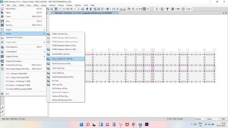
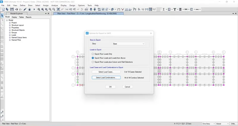
Step 26.
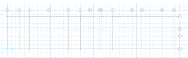
Next we open the safee 2020 and import the F2k file.
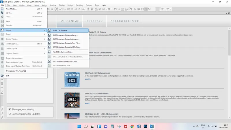
Then the F2k file has been opened In safe.
Step 27.
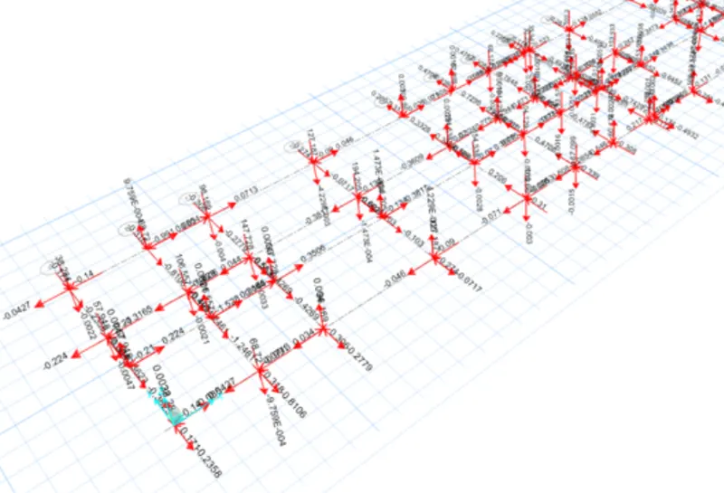
Next we select the show loads from the display option.
After select the show loads option, the new tab will be visible in that we select Dead above as Load Pattern.
Next we select we live as Above as load pattern.
Step 28.
Next we select the materials from define option to assign the materials.
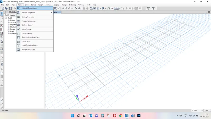
After selecting the materials the new tab appears, then we add new materials by selecting the add new materials.
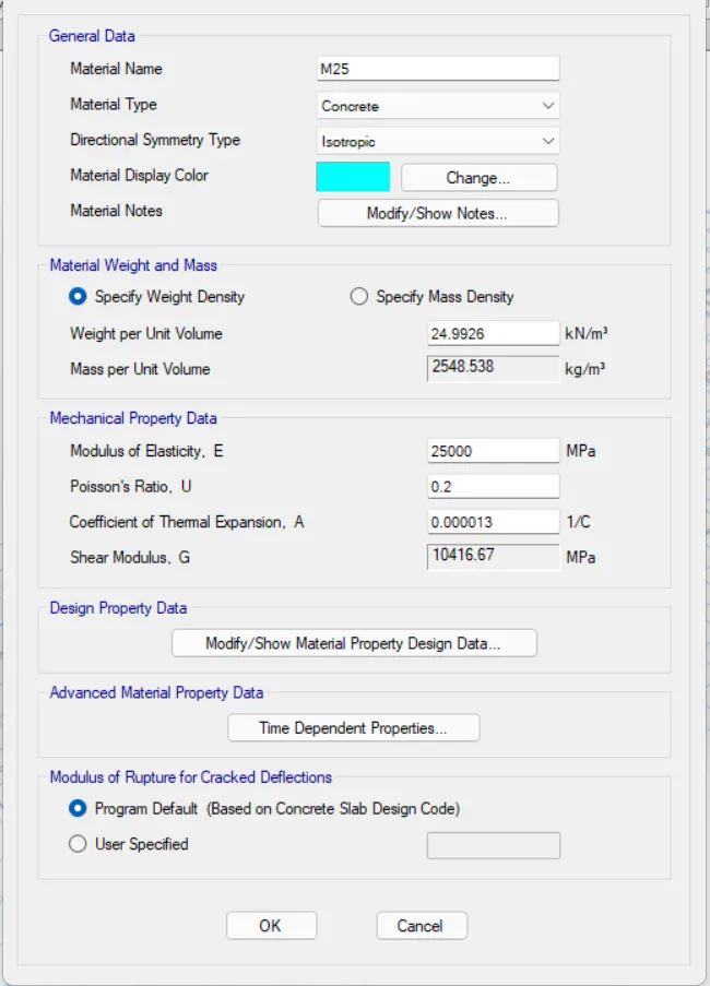
Now we need to add material type as concrete and grade as M25.
Now we add material type as rebar and grade as Fe500.
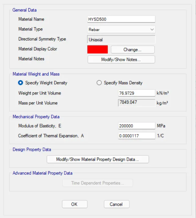
Now we add material type as rebar and grade as Fe415.
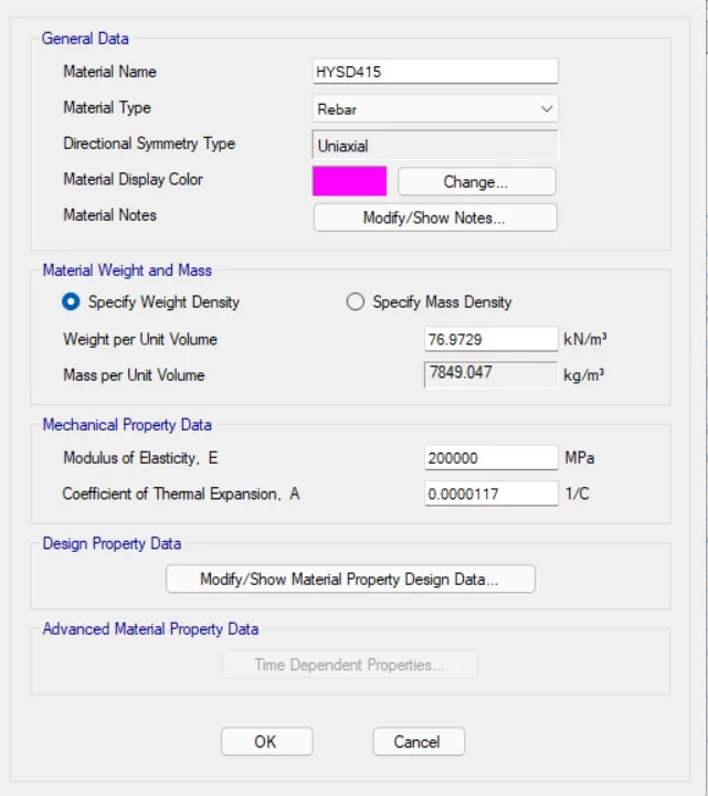
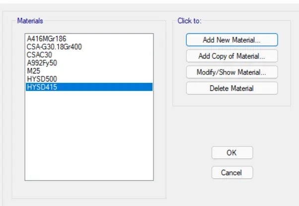
Hence the materials are assigned.
Step 29.
Now we need to select the slab properties from the define option.
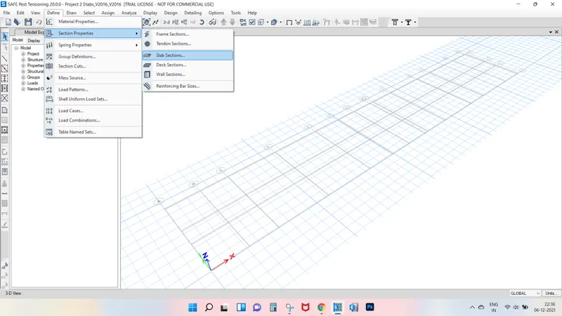
After selecting the slab properties the new tab will be visible, in that we need to select the add new property.
After selecting the add new property the new tab appears.
In that we need to put the property name as Pile Cap.
And we put the slab material as M25.
Thickness will be taken as 800mm.
Next we have click the Ok option.
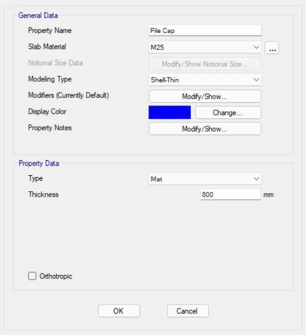
Next we need to again add the another slab property.
We need to put the property name as Pile 500.
And we put the slab material as M25.
Thickness will be taken as 800mm.
Next we have click the Ok option.
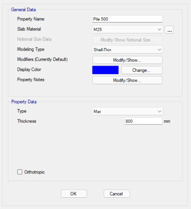
Next we need to again add the another slab property.
We need to put the property name as Column Stiff.
And we put the slab material as M25.
Thickness will be taken as 800mm.
Next we have click the Ok option.
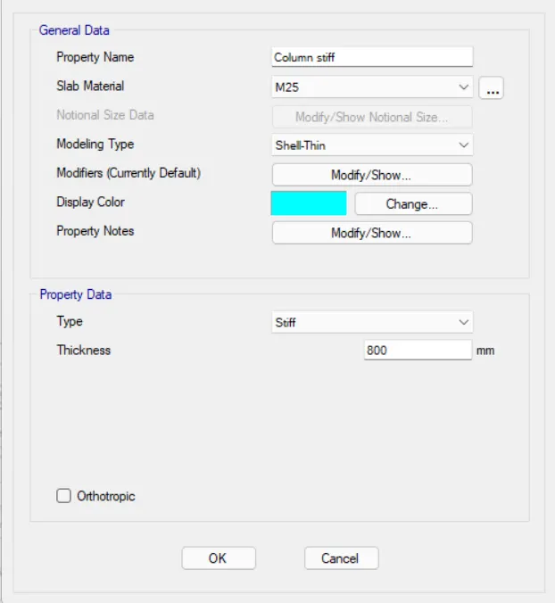
Hence the slab properties are assigned.
Step 30.
The piles cap are assigned.
The piles cap are assigned with 500 mm diameter.
The column are assigned with size of 450 x 650 mm and 650 x 450 mm.
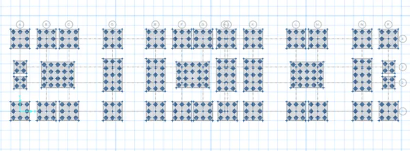
Step 31.
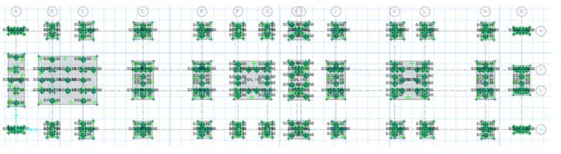
Next we need to assign the soil properties.
Now we select the soil properties from the Support data.
After selecting the soil properties the new tab appears, in that we select the SOIL 150 and press OK.
Step 32.
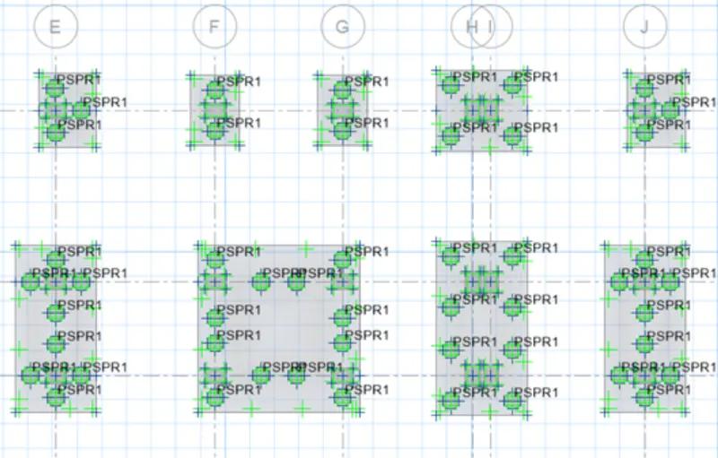
Now we select the points to assign the spring for the piles.
Next we select the point spring from the Support data from assign option.
Next the point spring properties tab will be visible.
Next we select the Modify?show property, then the new tab appears, in that we take 490.87 kn/mm In translation Z.
Spring Constant = EA/L
E = 25000
A = 196349. 54
L = 10000 mm.
Spring Constant = 25000 x 196349.54 / 10000 = 490.87 Kn/mm.
Hence the points springs are assigned successfully.
Step 33.
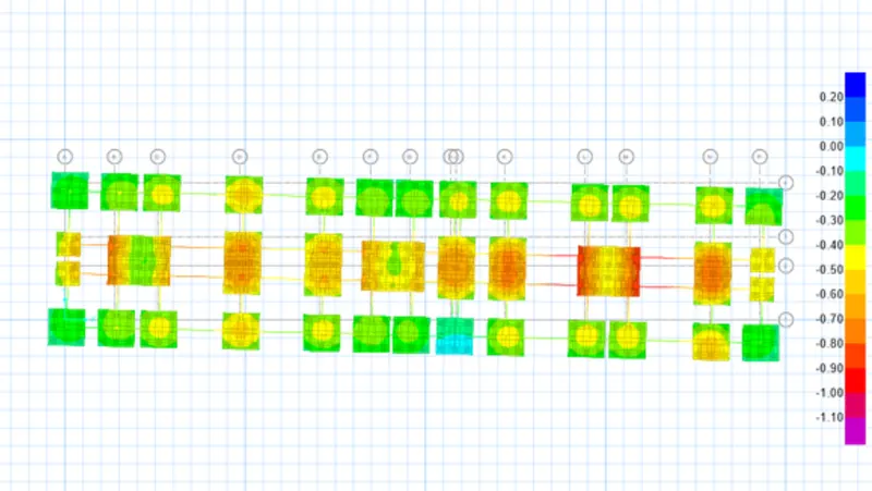
Now we have to do the run analysis.
then the deformed shape will be visible after complition of run analysis.
Step 34.
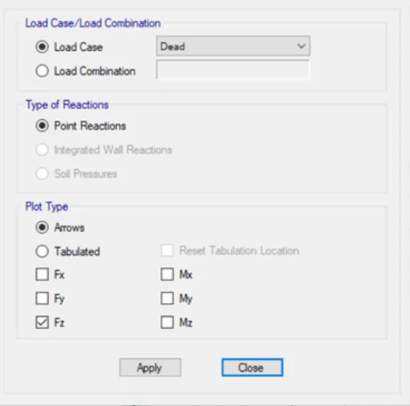
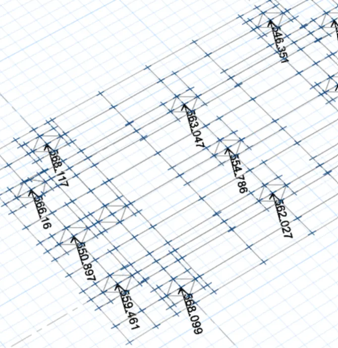
Next from the display option we select the Show Reaction Forces.
After selecting the Rection forces option the new tab will be visible, in that we put the load cases as DEAD.Next click on the apply button.
Step 35.
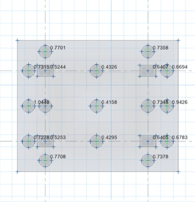
Next from the display option we select the Show purching shear design.
Now we punching shear values will be visible, the values are less than 1.
Then there is no error in Punching Shear.
If the punching shear values are more than 1, we need to increase the pile cap size.
Step 36.
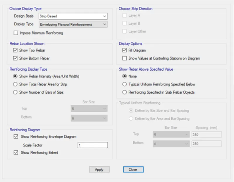
Next from the Display option we select the Show slab design.
After selecting Show slab Design option the new tab will be visible, then click on the apply button.
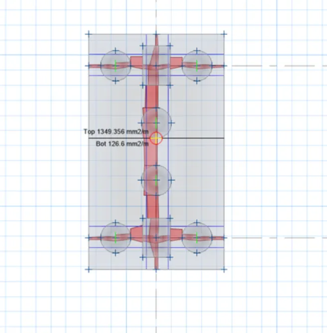
Now here we see that the slab strip design results, According to the slab strip design result we can provide the reinforcement at the top and bottom.
Result -
The G+3 Hostel Building has been Designed and analyzed in Etabs.
And The foundations are designed and analyzed in Safe.